Creating a Floor plan, Footing detail and Isometric view using AutoCad
AIM: To create floor plan ,footing detail and isometric view using AutoCAD
INTRODUCTION :
PROCEDURE :
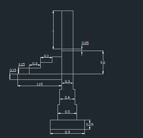
1 . C.S. OF LOAD BEARING WALL OVER SPREAD FOOTING
- At first we have to check and set dimensions
- Also we need to put object snap on "ON" mode so that it will be easy to identify end points ,midpoints etc.,
- Starting with line command i.e., L-enter , draw the lines as per dimensions
- Using "DIM" command specify the dimensions of the figure
- We use snipping tool for taking screenshot
- Finally ,save the picture
2. C.S. ISOLATED FOOTING
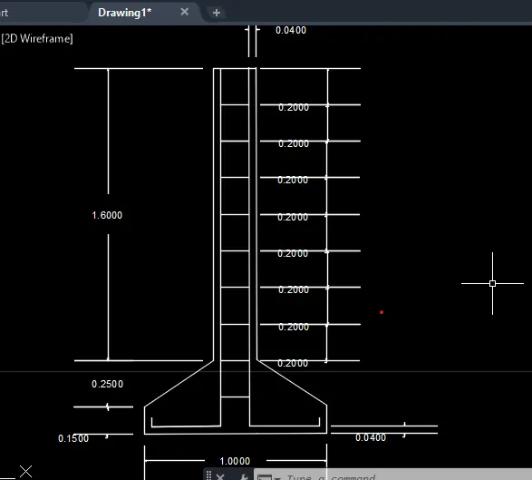
- At first we have to check and set dimensions
- Starting with line command i.e., L-enter , draw the lines as per dimensions
- Using command "O" to make offsets
- Also command "tr" is used for trimming
- Using "DIM" command specify the dimensions of the figure
- We use snipping tool for taking screenshot
- Finally ,save the picture
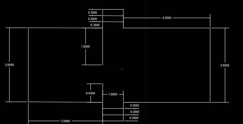
3. LINE DIAGRAM OF TWO BEDROOM BUILDING
- At first we have to check and set dimensions
- Starting with line command i.e., L-enter , draw the lines as per dimensions
- using command "O" offest is done
- Using "DIM" command specify the dimensions of the figure
- We use snipping tool for taking screenshot
- Finally ,save the picture
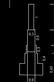
4. C.S. OF LOAD BEARING WALL SHOWING FOUNDATION DETAILS
- At first we have to check and set dimensions
- Also we need to put object snap on "ON" mode so that it will be easy to identify end points ,midpoints etc.,
- Starting with line command i.e., L-enter , draw the lines as per dimensions
- Using "DIM" command specify the dimensions of the figure
- We use snipping tool for taking screenshot
- Finally ,save the picture
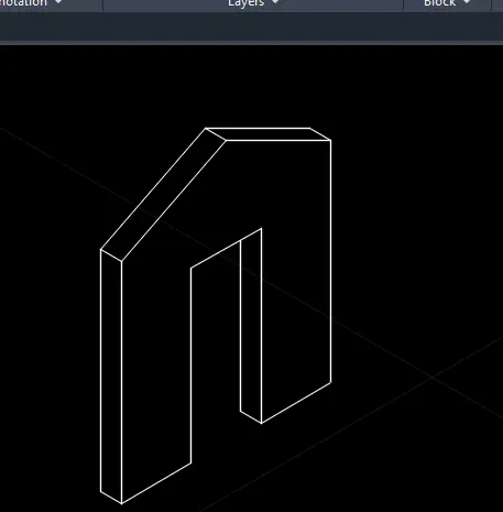
5.ISOMETRIC VIEW OF GABLE WALL
- At first we have to check and set dimensions
- Also we need to put object snap on "ON" mode so that it will be easy to identify end points ,midpoints etc.,
- Then click on isometric drafting to set isometric view
- It show three views
- as per the figure we need to set the vies and draw lines accoring to dimensions
- Using "DIM" command specify the dimensions of the figure
- We use snipping tool for taking screenshot
- Finally ,save the picture
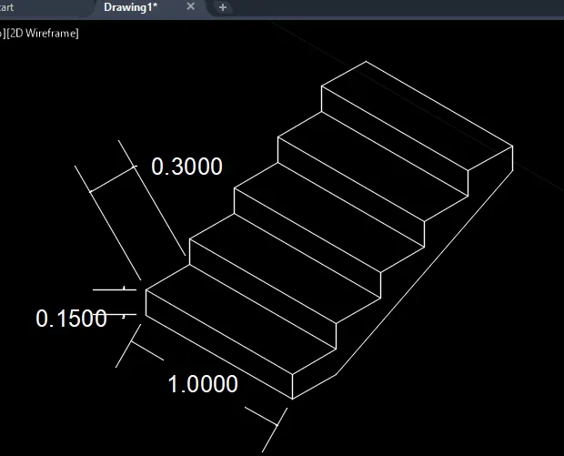
6. ISOMETRIC VIEW OF STEPS
- At first we have to check and set dimensions
- Then click on isometric drafting to set isometric view
- It show three views
- as per the figure we need to set the vies and draw line accoring to dimensions
- Using "DIM" command specify the dimensions of the figure
- We use snipping tool for taking screenshot
- Finally ,save the picture
Result :
Created Floor Plan ,Footing detail and Isometric view using AutoCAD