Creating 3D Isometric view of various structural elements in AutoCAD
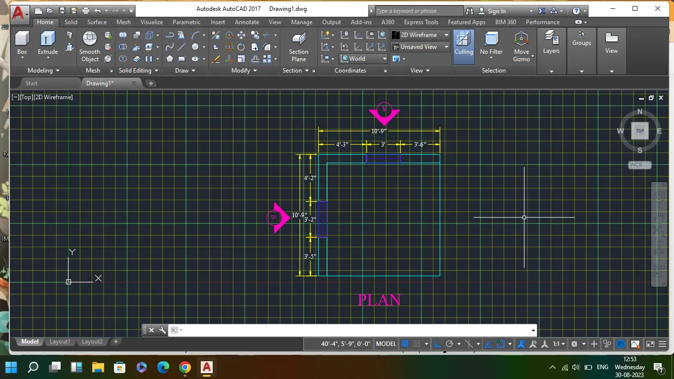
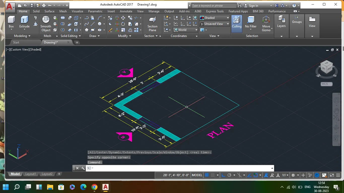
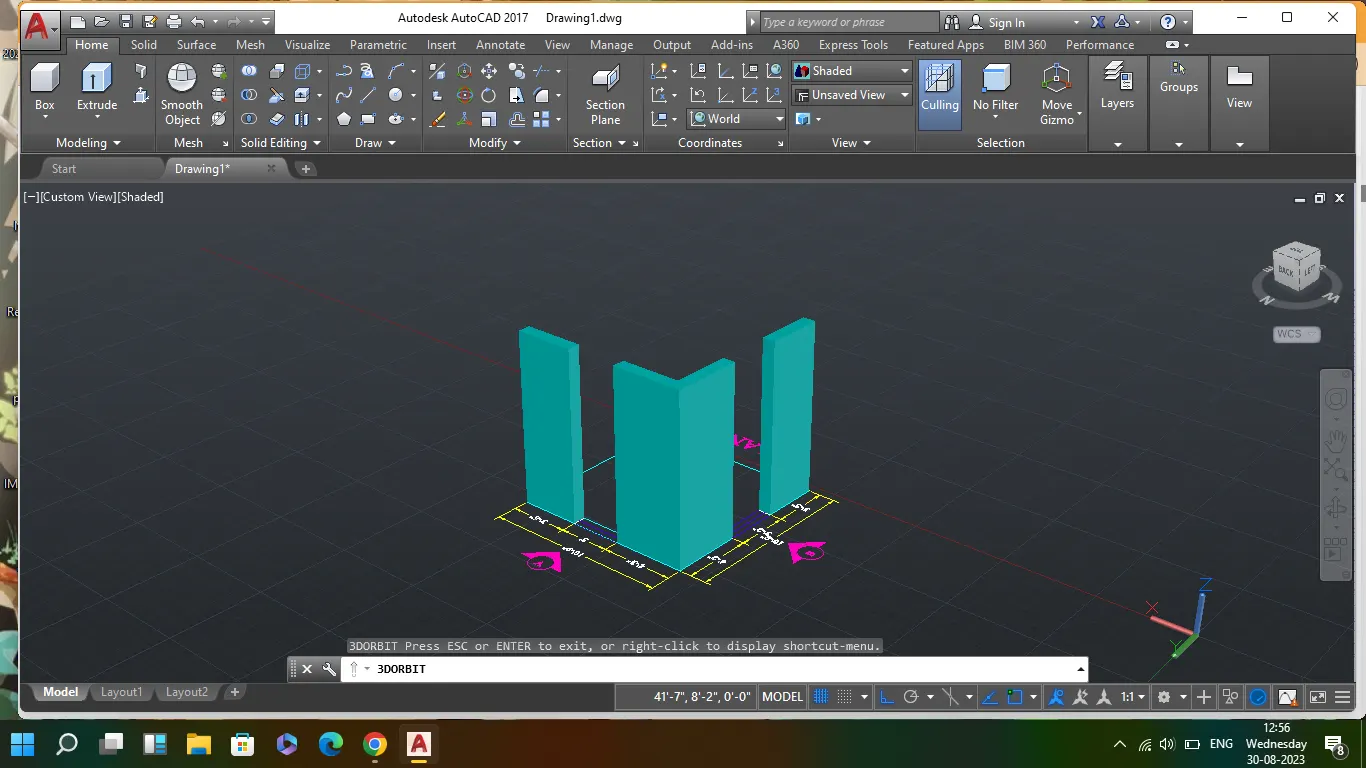
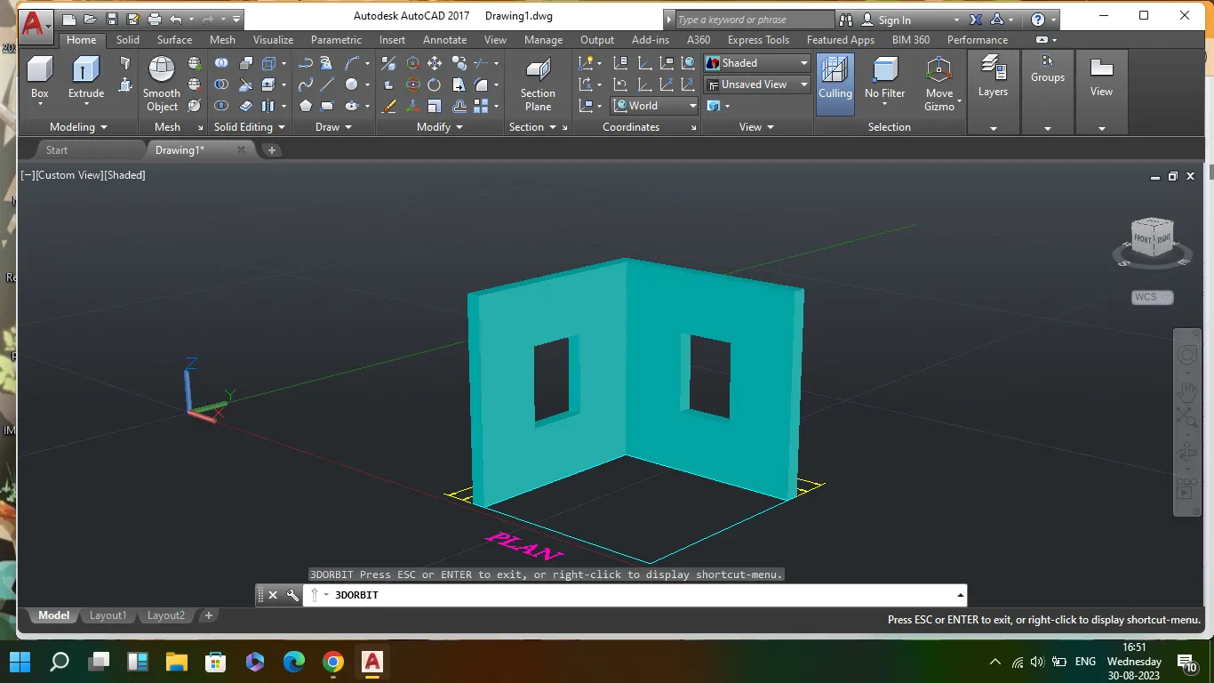
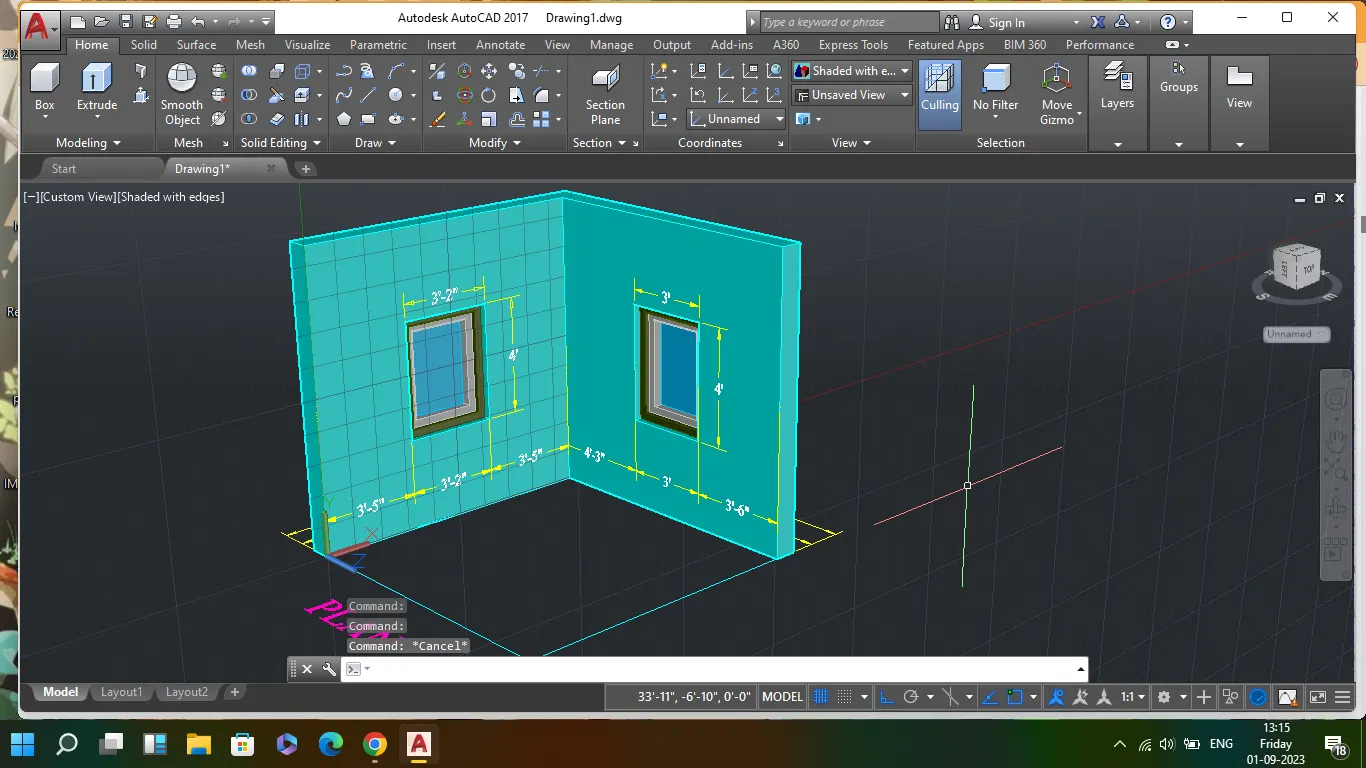
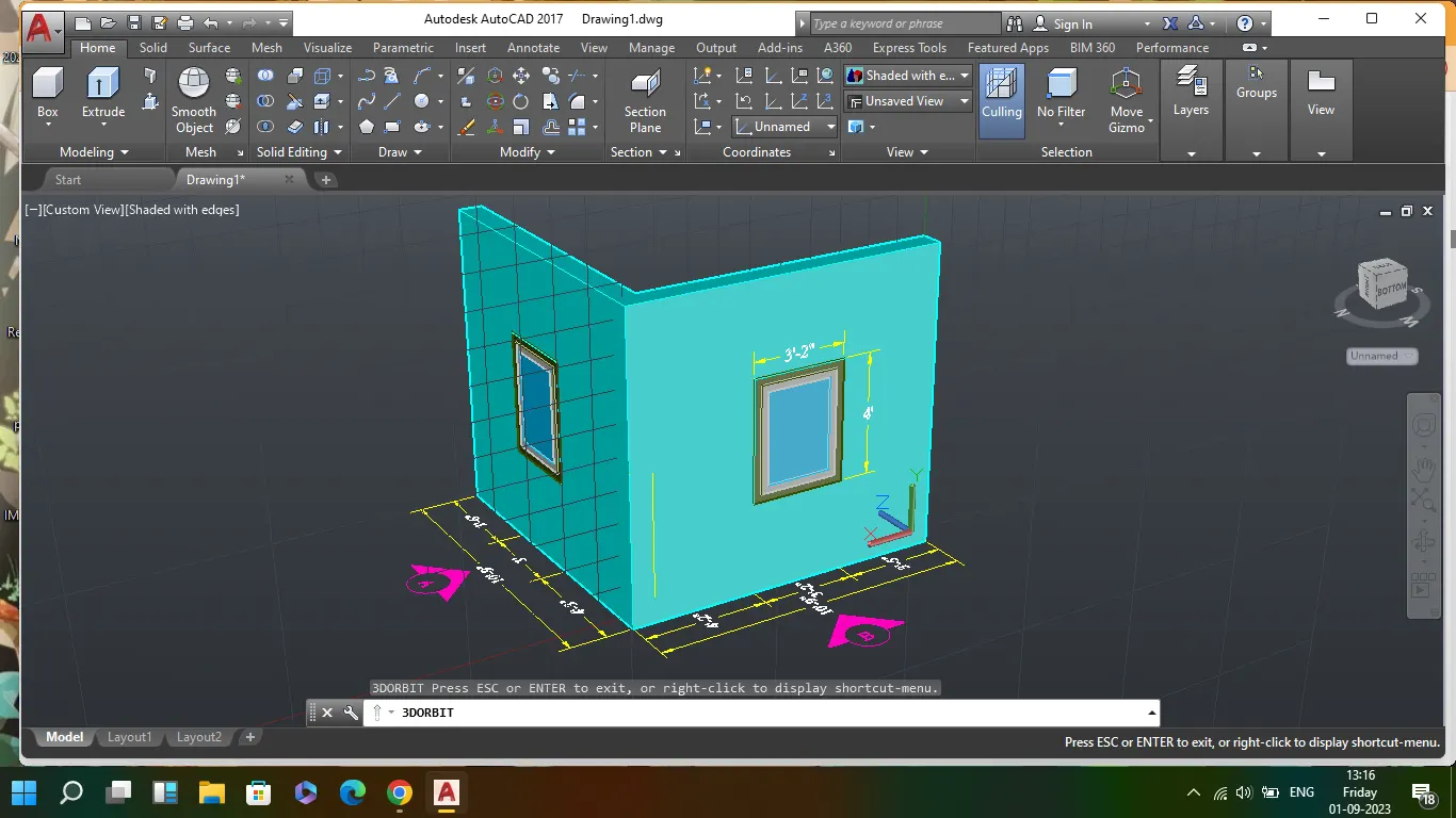
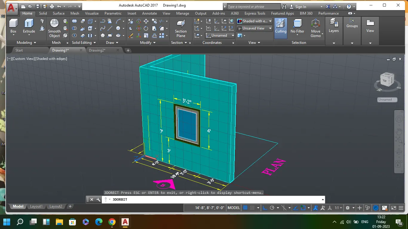
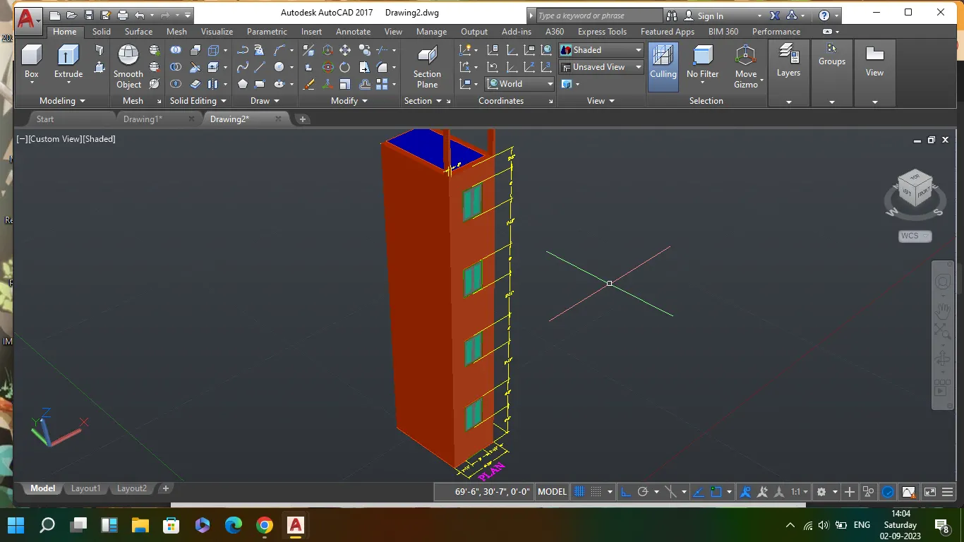
To show the 3D isometric view of given plan in its elevation drawing
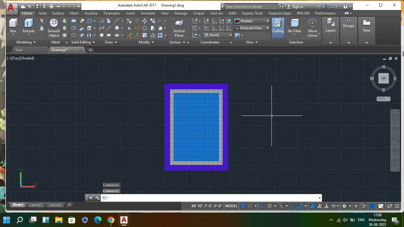
- open autocad and select 3d modling, set all the necessary units and limits
- create a 2D plan over the XY plane and using DIMLINear give dimensions
- create respective layers accoring to drawing objects and assign the layer to dwg
- using Boundary command assingn boundary to the walls of plan along with respective layers choosen
- using Extrude command ,extrude the walls to the given height and extrude the wall portion till window sill level and providing gap for window from lintel level to top
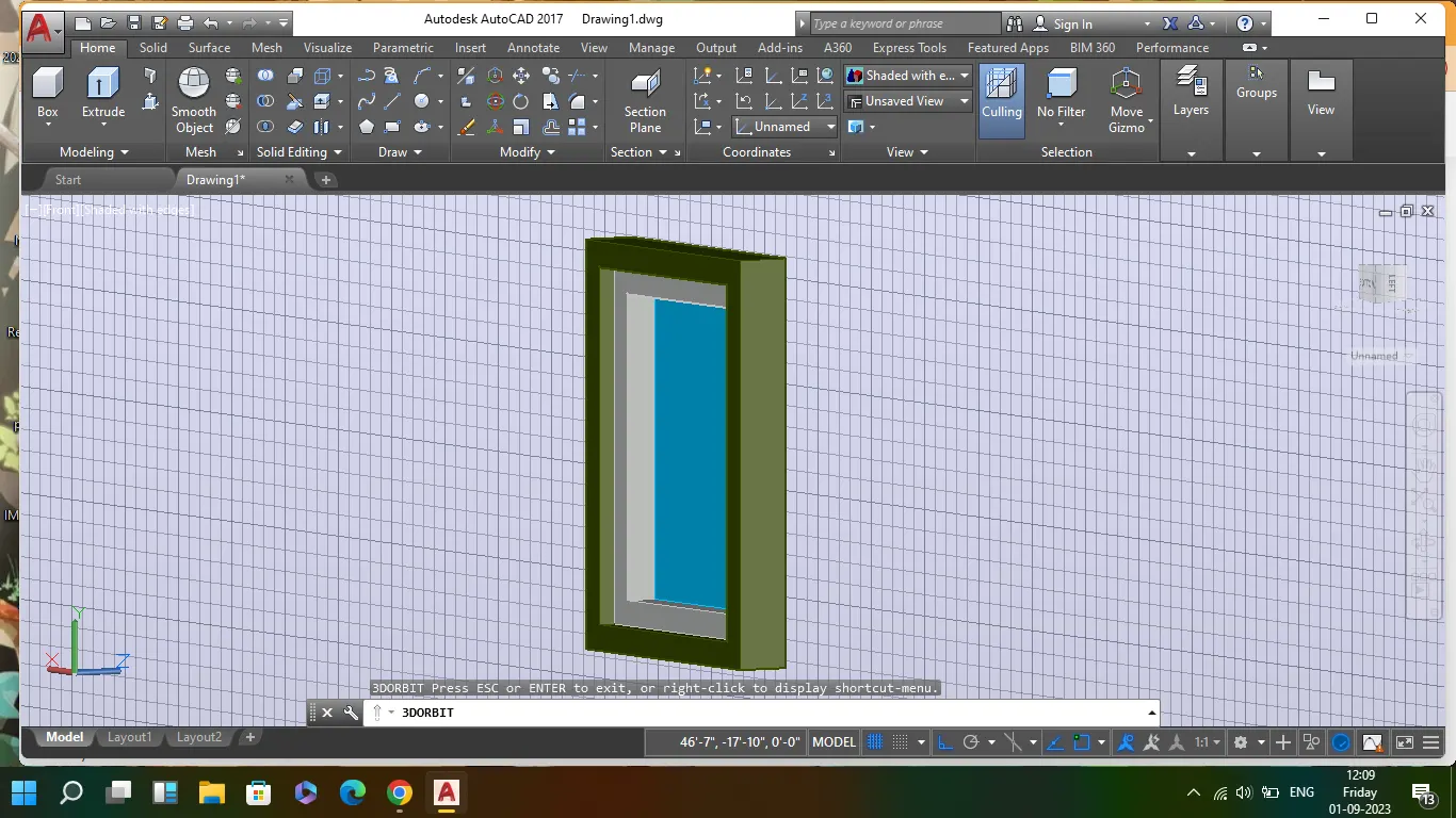
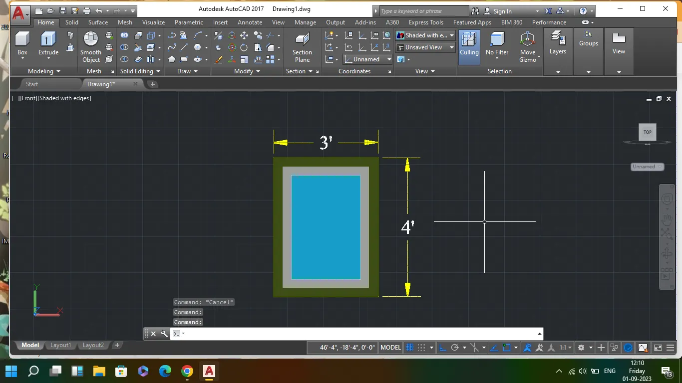
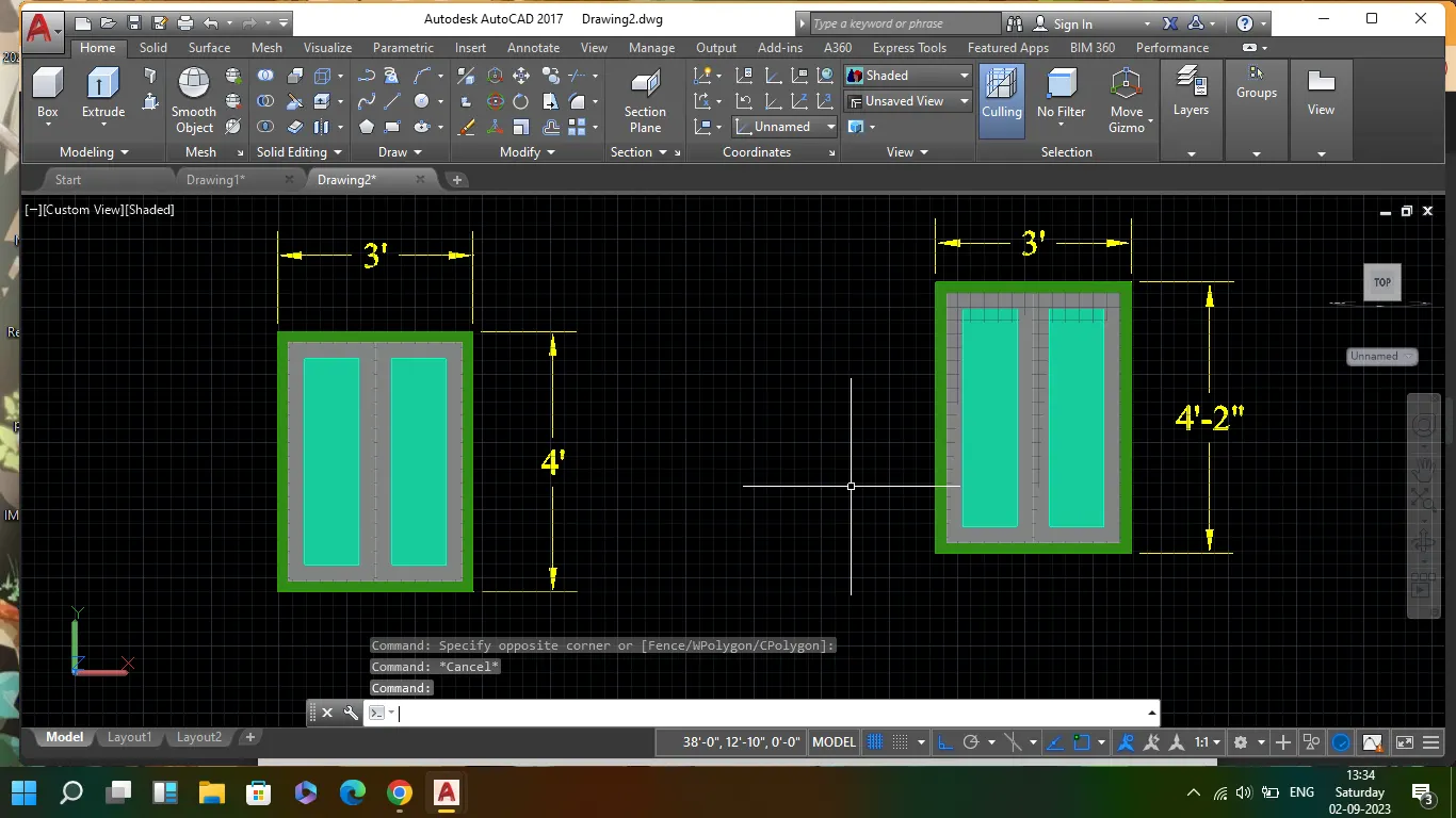
- take required window width and height , draw a window in 2D plane. Assign the layers as window frame, mullion and glass
- extrude the each components saperately according to the given width
- using Rotation3D rotate the window in required plane and attach the window to building as per the drawing
- using UCS command set the XY plane and using DIMlinear give respective dimension
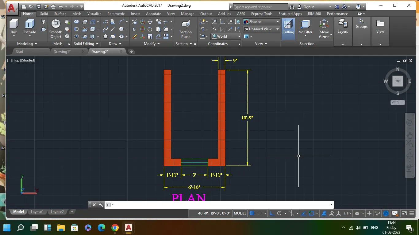
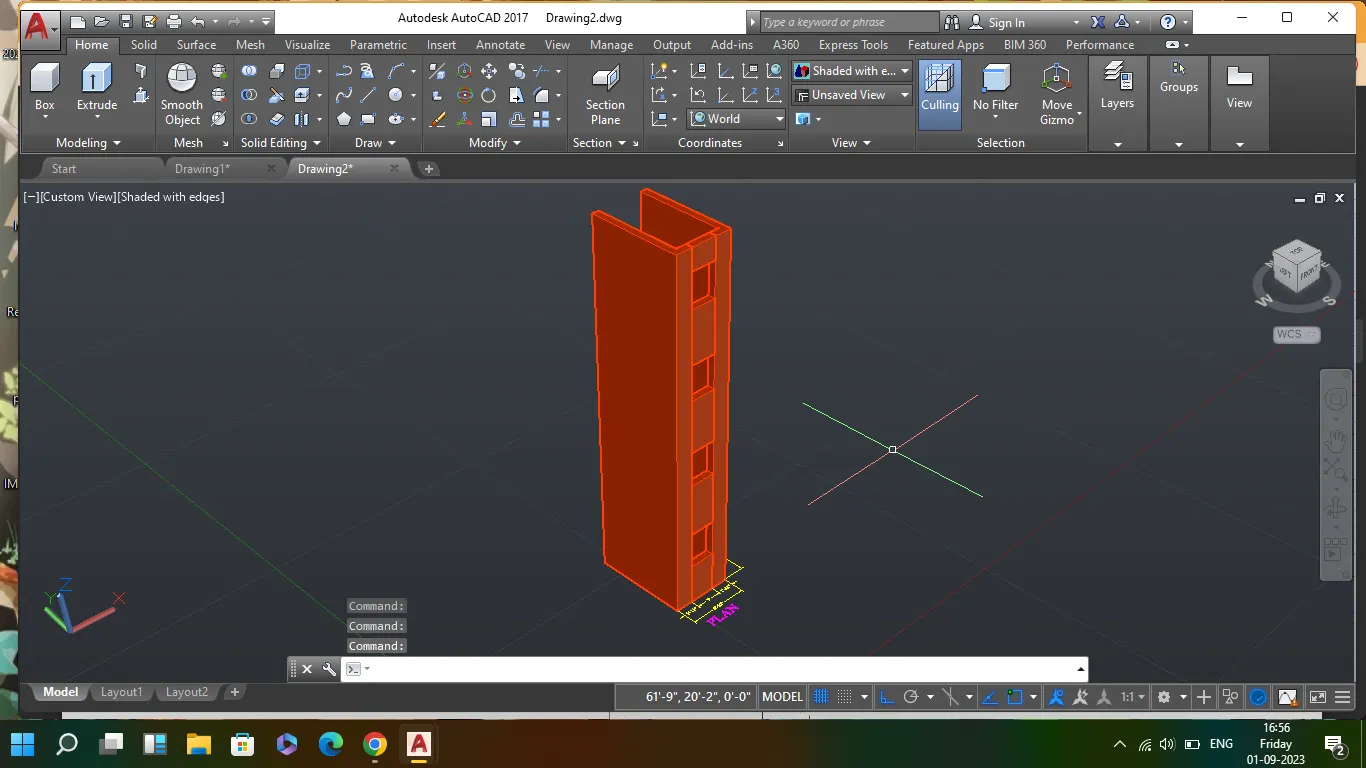
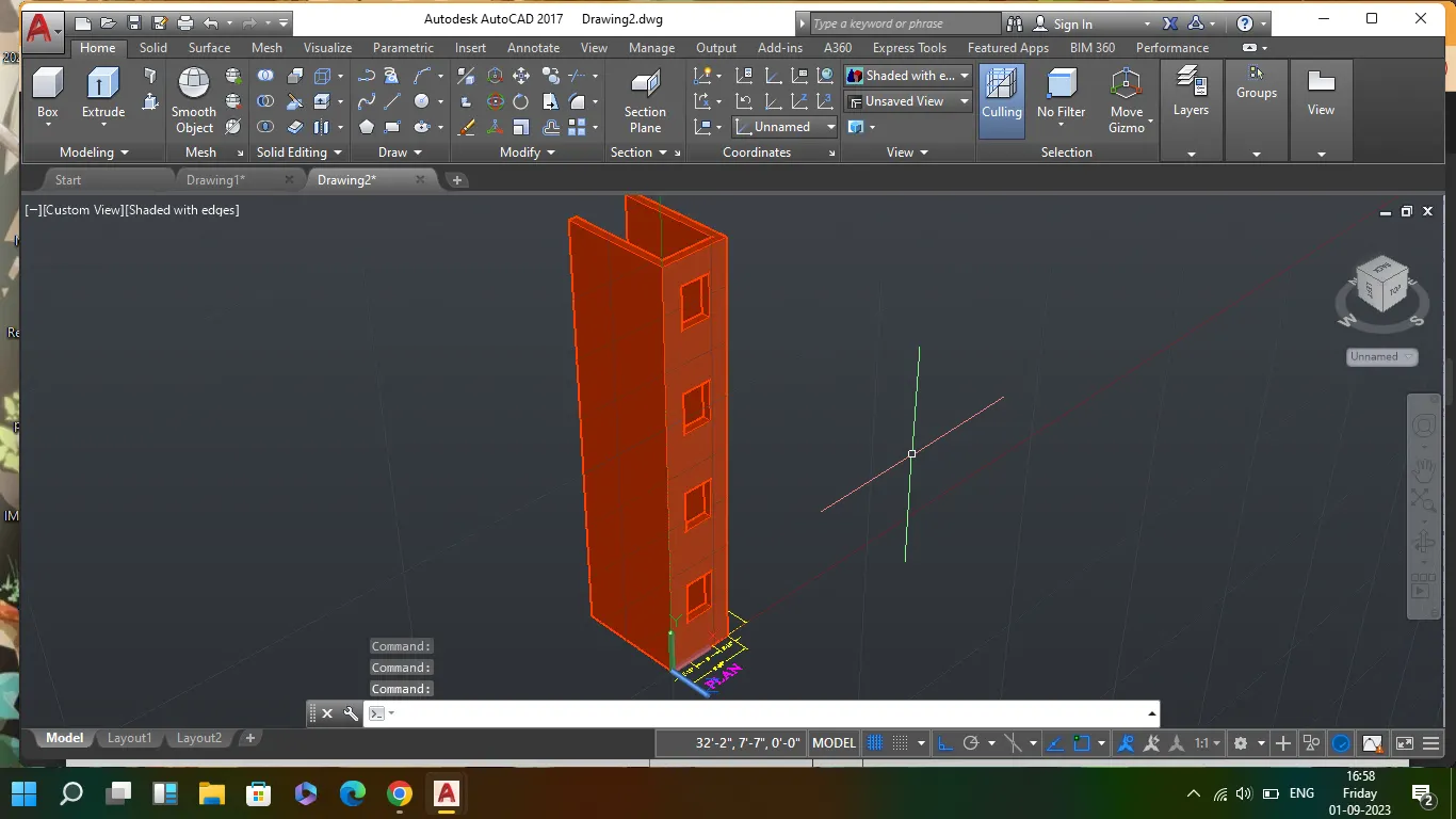
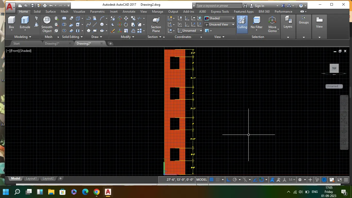
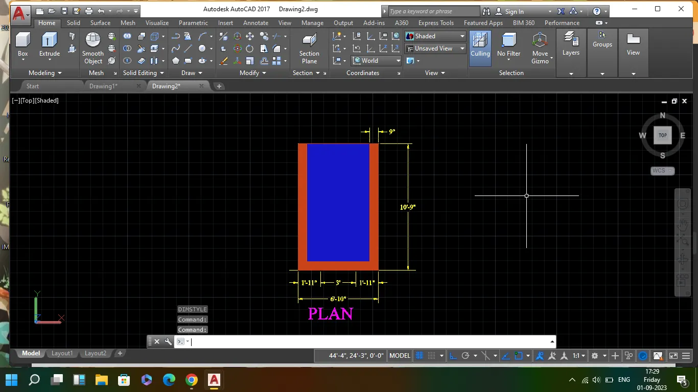
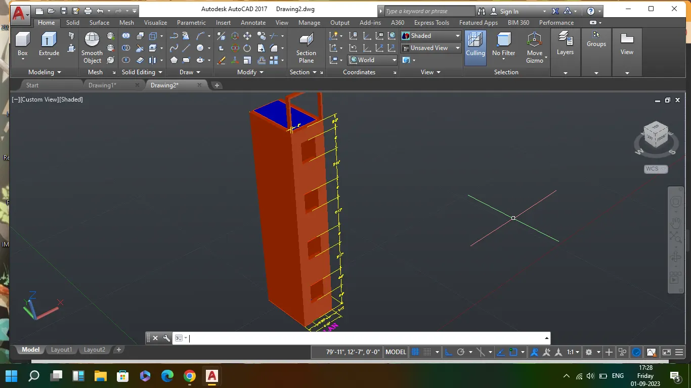
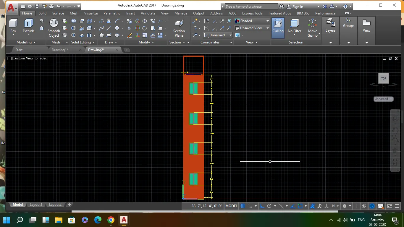
To show the elevation of given plan and window detailing
- draw the 2D plan on the XY plane and assing all the components of building and windows in the layer
- using Extrude command extrude the building till the given height and to give space for window. Draw a rectangle of required window size and copy paste it in each sill and lintel level at every floor of the building
- extrude the rectangle till the sill and lintel in each floor and using Union command join all the structure
- take the window dimension saperately and draw its components along with assign to respective layers, using Boundary command assing each components like window frame, mullion and glass using respective layers for each components
- extrude the each components along with choosing its respective layer to its certain depth and using Rotation3D rotate the window to required plane
- attach the window to the building using copy command
- using UCS command give respective dimensions
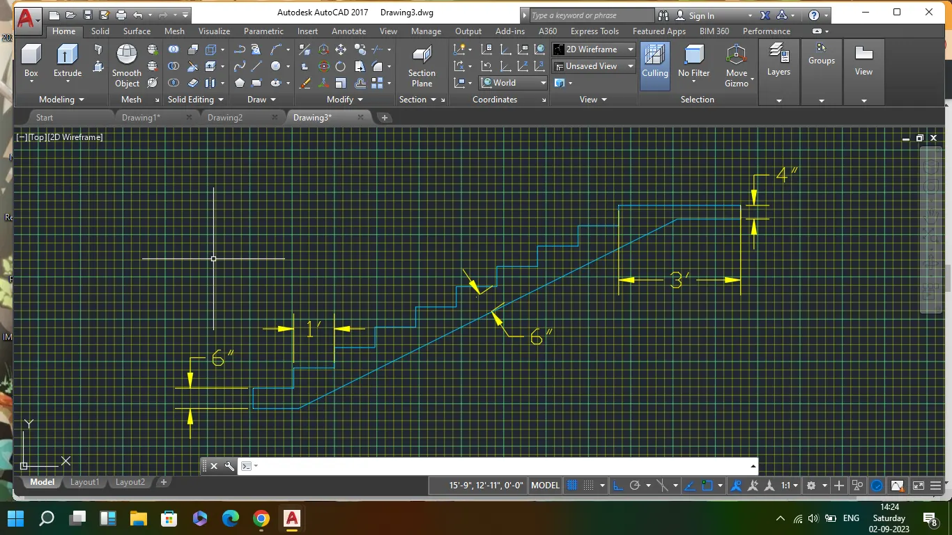
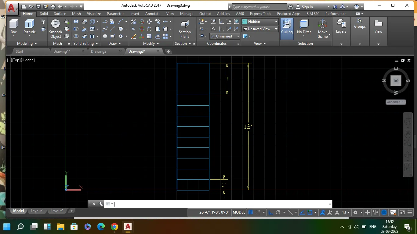
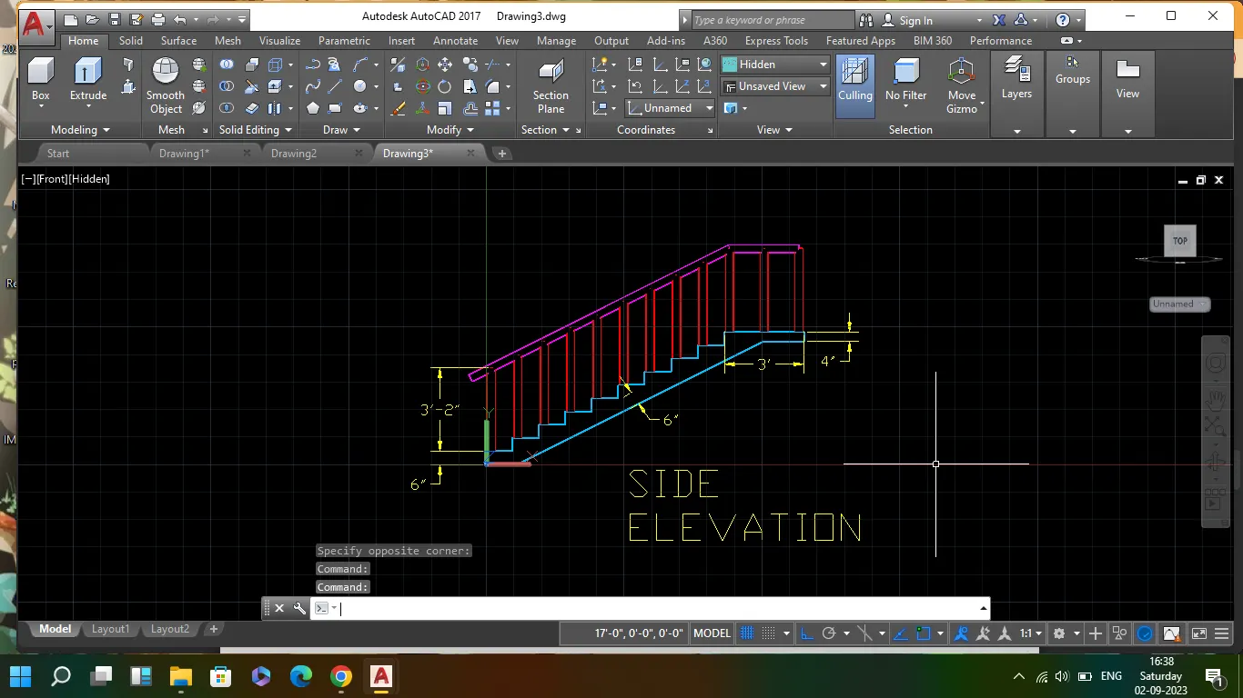
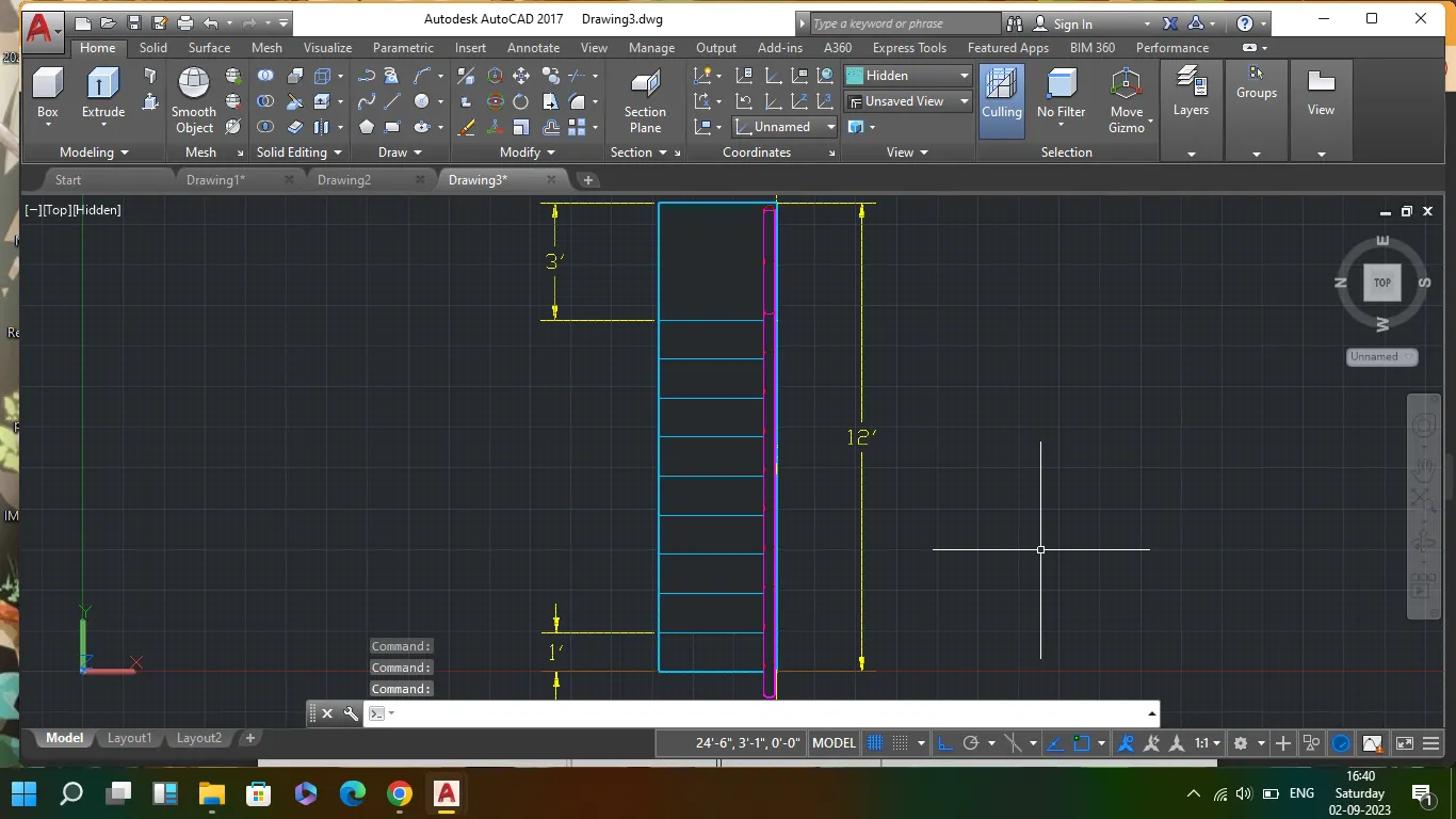
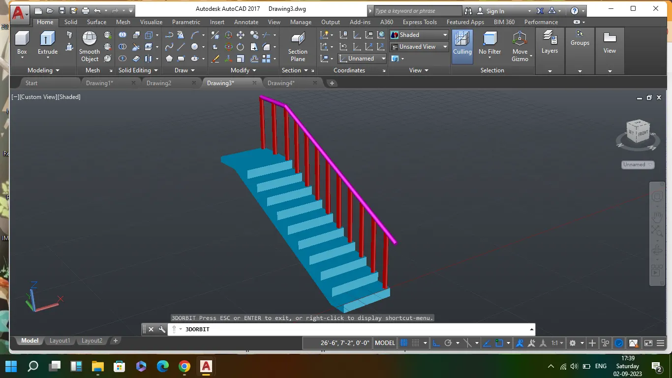
To draw a stairs along with railings and gaurd rails in 3D
- draw the 2D plan of stairs on the XY plane and join the each lines using Join command and using boundary asign the region
- using 3D rotate command, rotate the stairs in requrired plane and using Extrude command extrude the stairs for given width
- using ucs command draw a gaurd rail along the each steps of stairs
- joining each gaurd rail top draw a polyline and draw a circle saperately of required diameter
- using Sweep command click on circle first then on the polyline, the railing is generated
- using ucs dimensions are given and using PLan command the plan of stairs is taken
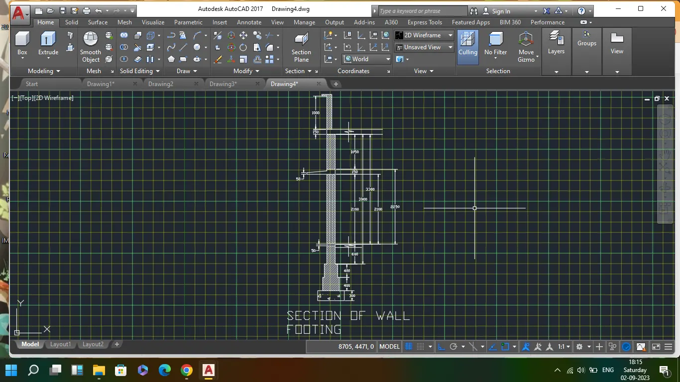
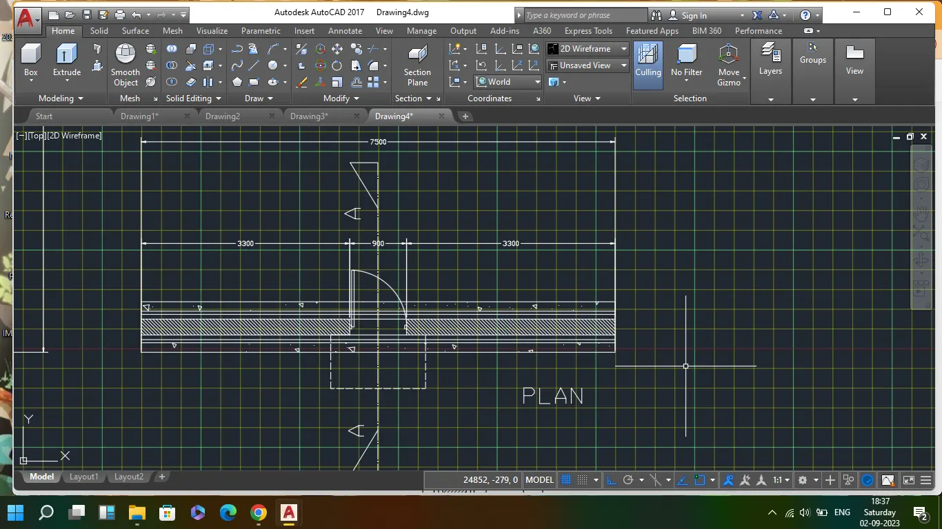
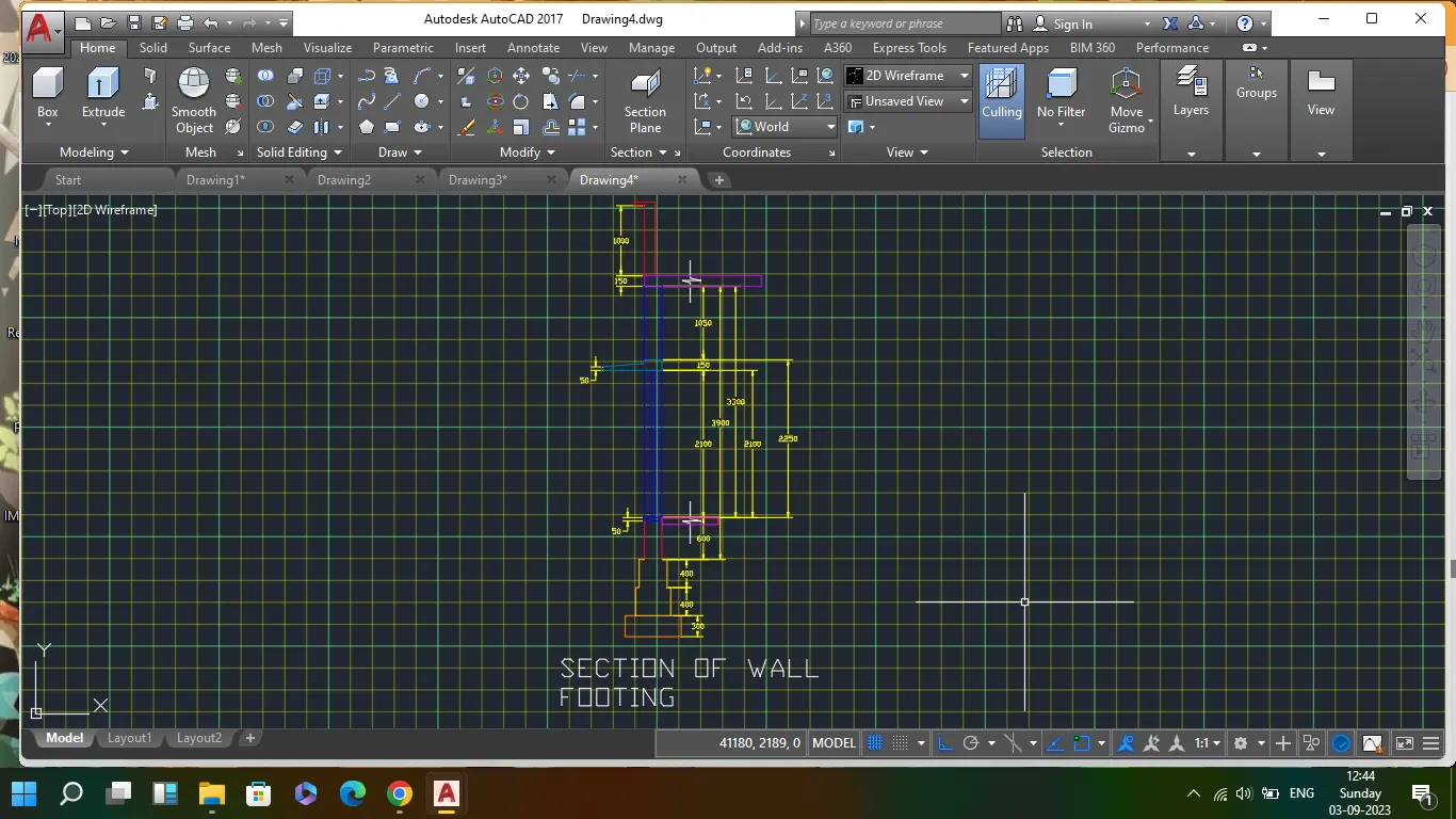
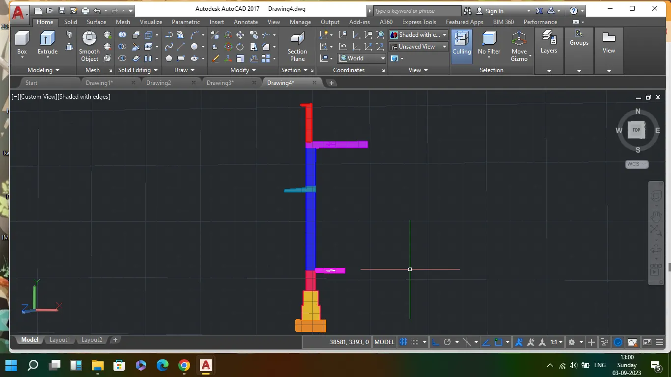
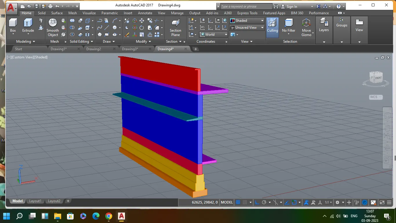
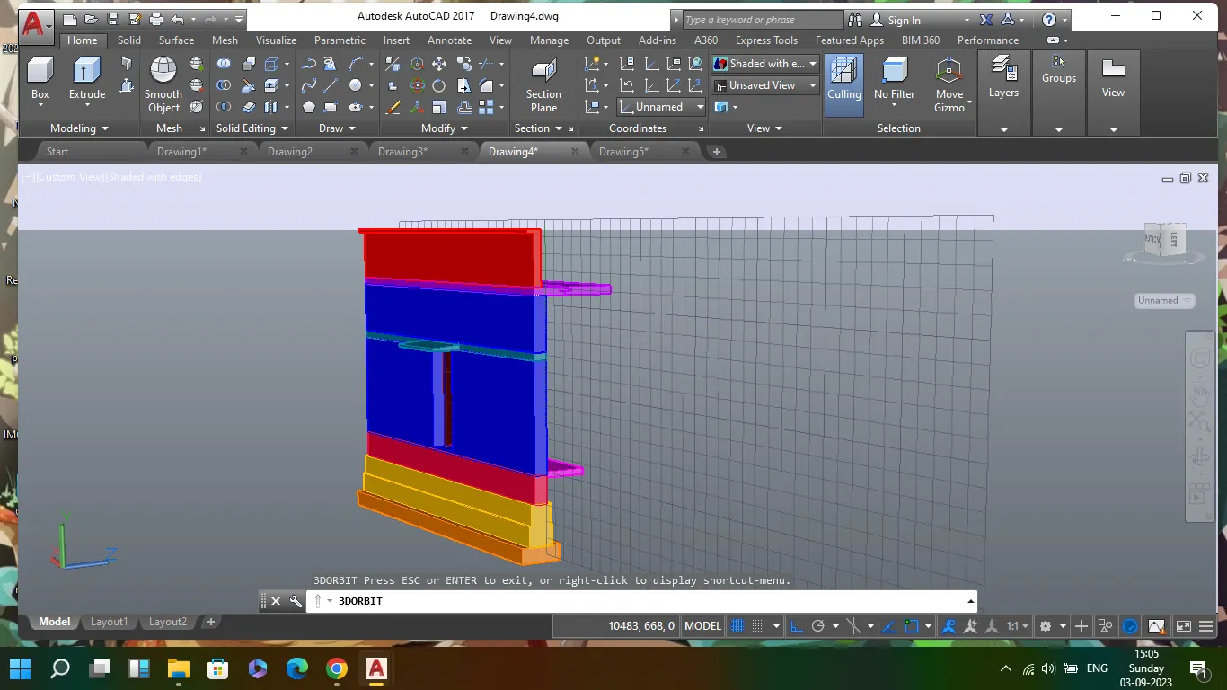
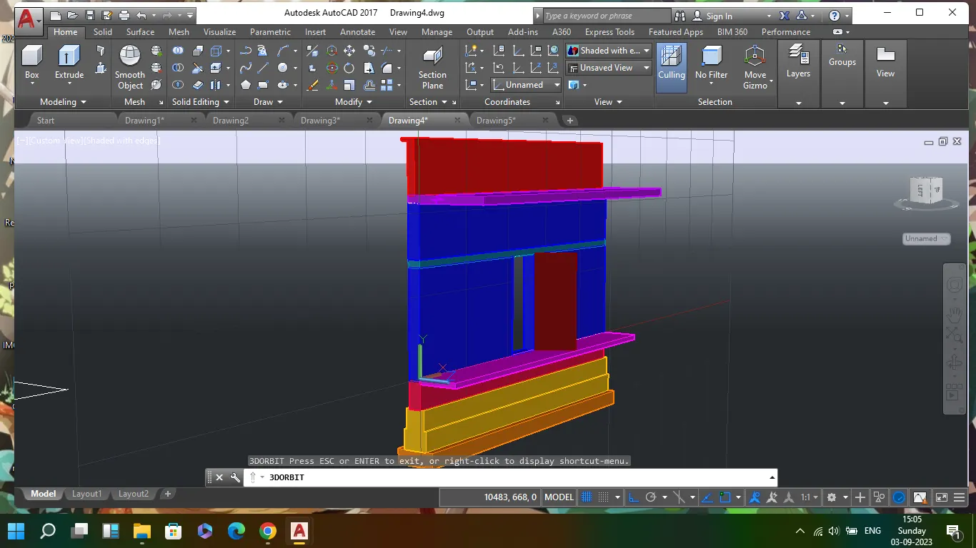
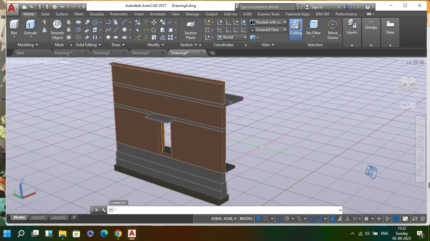
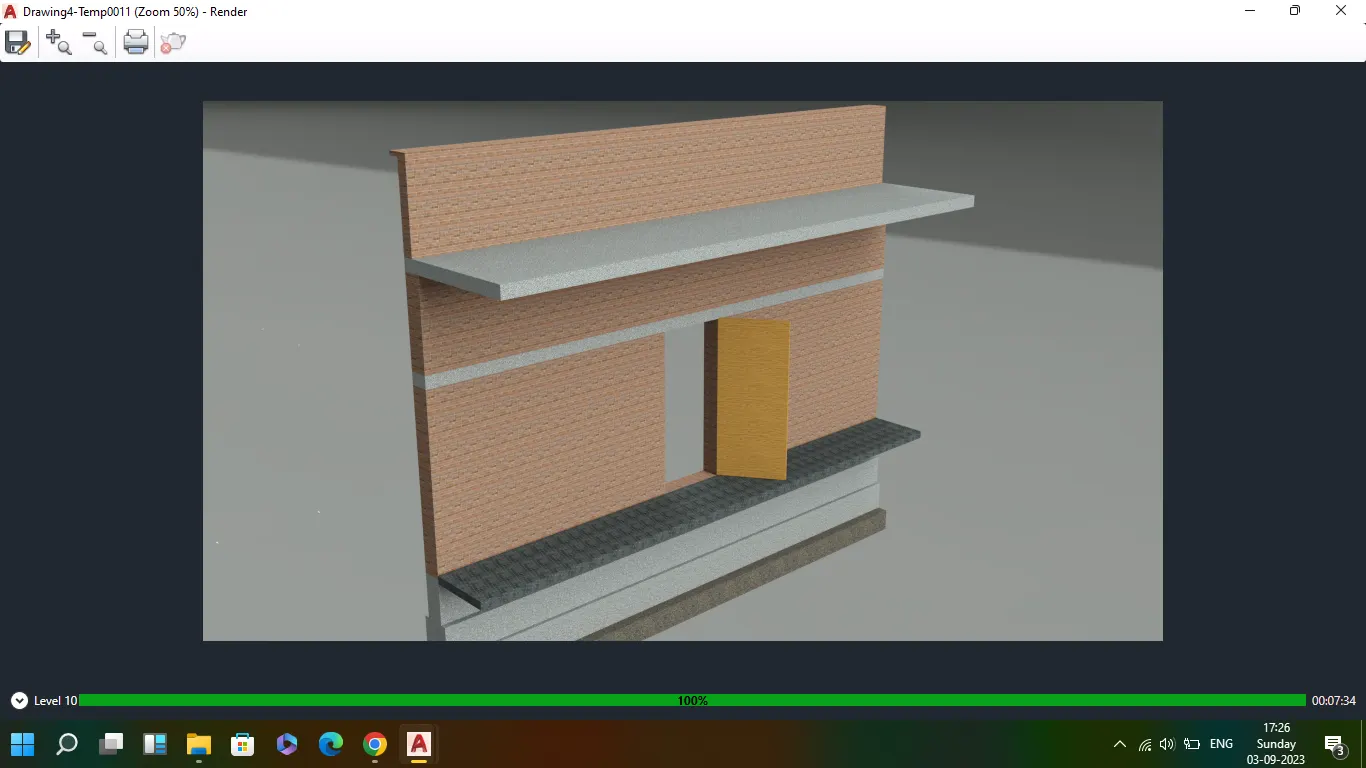
To show the section of wall along foundation in 3D model also rendring with materials assigned
- draw a 2D plan over the XY plane usings lines and offset commands. The cross section and a plan of wall is drawn
- assign all the components of wall, foundation, door and etc in different layers
- using boundary command region the c/s dwg and using rotate 3D, rotate the dwg in required vertical plane
- extrude the wall components to the given length and using subsatract command assign the door in the wall
- using 3D orbit command rotate the dwg and take screenshots,
- using Rmat command , the different materials are assigned to different components of wall as per DWG
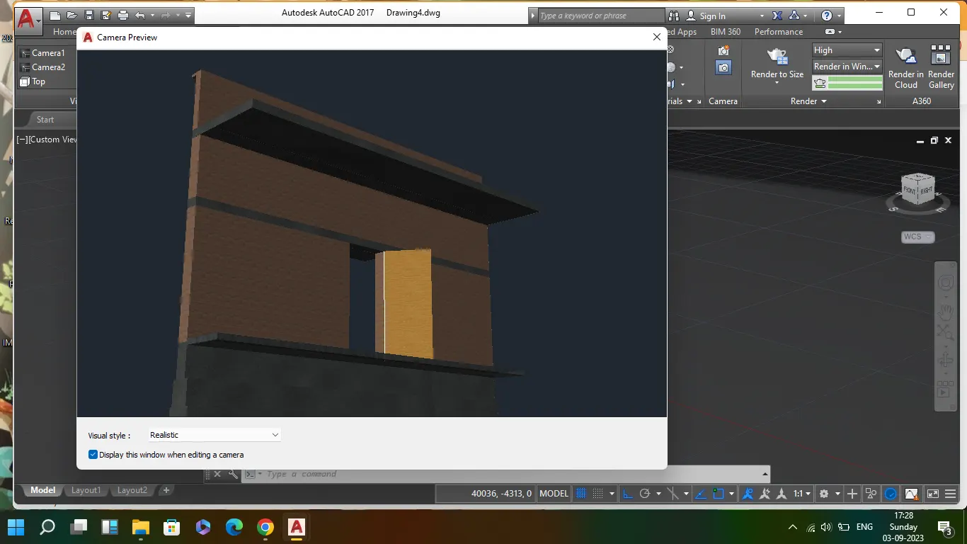
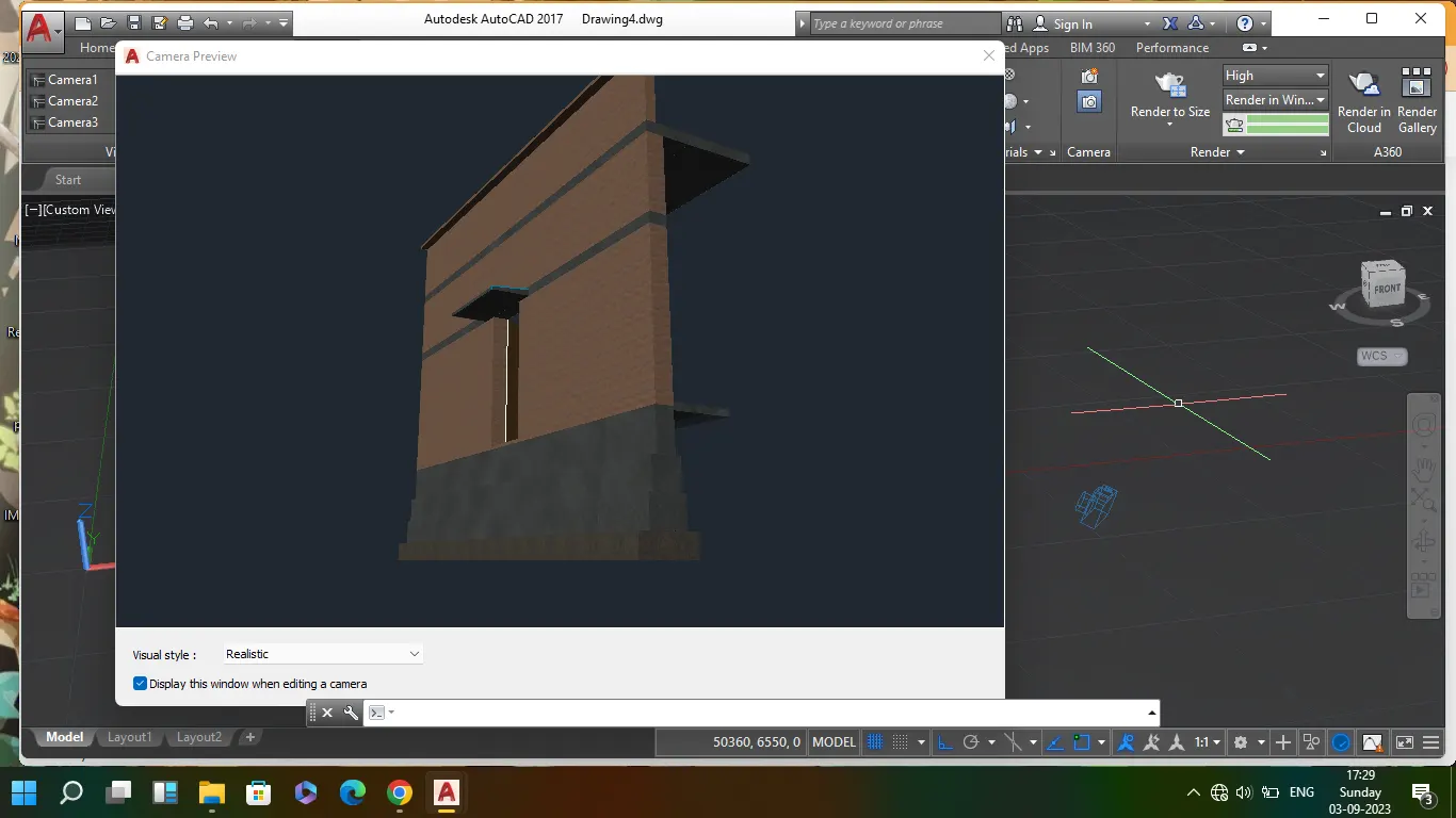
- using Camera command, place camera in required angle and take pics of it
- using required Light command place the light in required direction and shadow command to required angle
- using Render command render the whole wall section using high resolution
- the rendered image of wall section is obtained