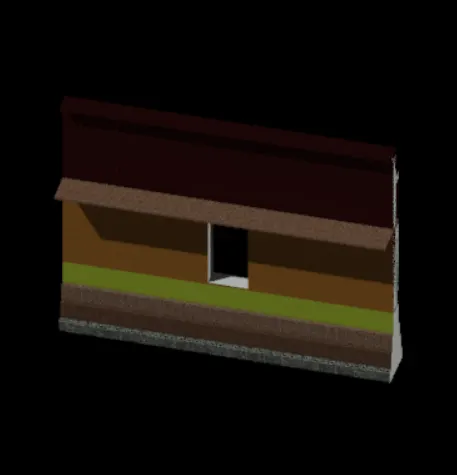
Creating 3D Isometric view of various structural elements in AutoCAD
1.AIM:
Create a 3D Isometric View of the building with plan and elevation given.
PROCEDURE:
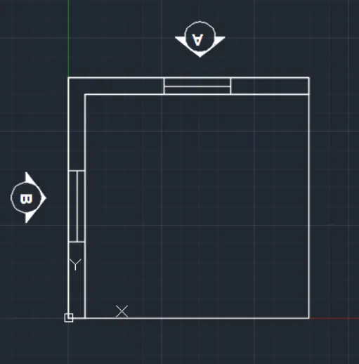
1)Draw the line for 3'5",3'2",4'2",4'3",3',3'6"
2) draw the window for 3'2" and other side 3'
3) take the offset for 9"
5) using of dli cmt mark the dimension
6) Insert the text using mtext cmt
RESULT:
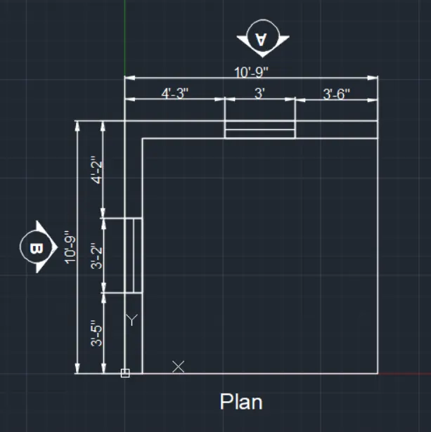
7)hide the dimension layer
8) type the bo cmt to create boundary region for walls
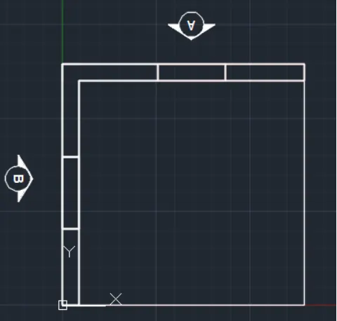
9) go to back view and create the window using rectangle cmt
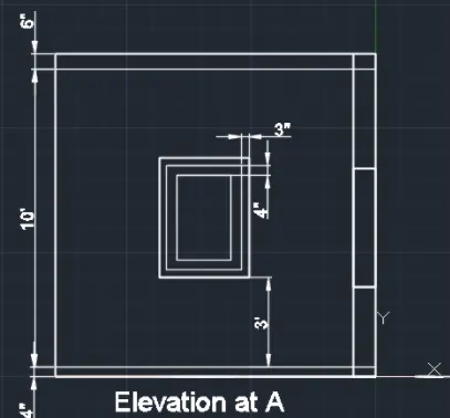
10) this is elevation A
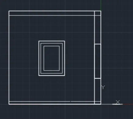
11) Provide the dimensions
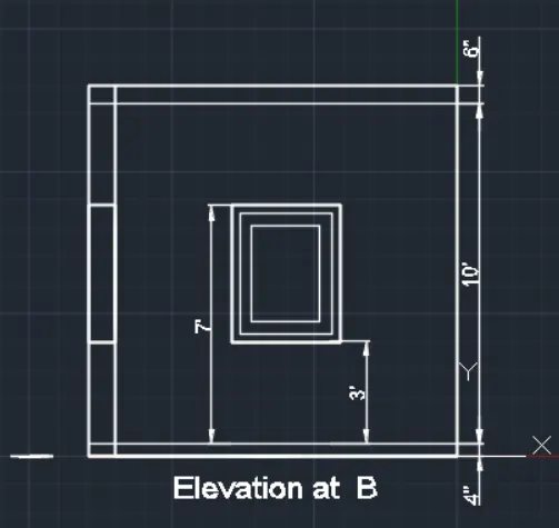
now similarly draw the elevation at B taking the right view
12) now draw the rectangle at the window portion and create the boundary
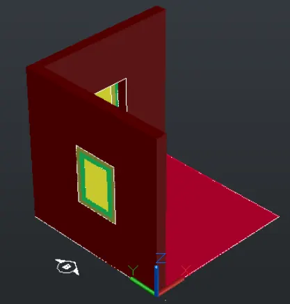
13) then extrude the rectangle to complete the wall
14) then final isometric view as given below
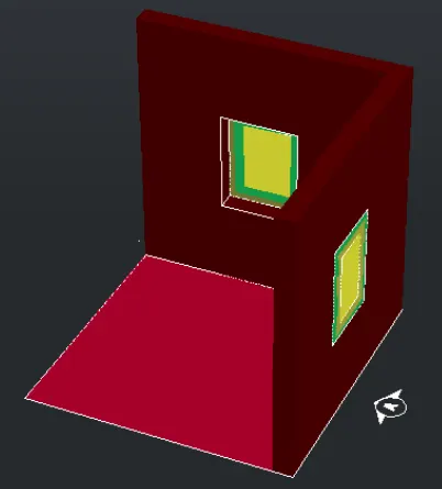
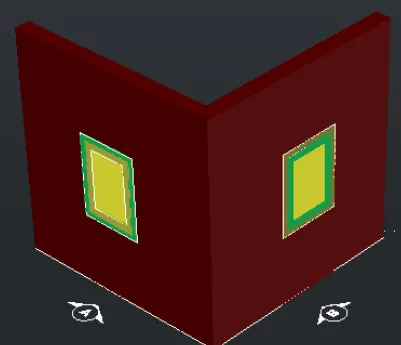
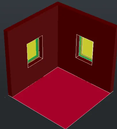
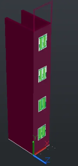
2.AIM: Create the 3D View of the Building Façade as given in the plan and elevation. Also, see the detail of the window.
1) Now choose the line cmt and create the plan as given
2) provide the hatch using hatch cmt
3) using of dimlin cmt provide the demension using the mtext cmt
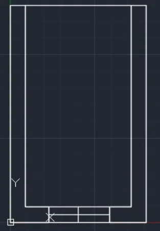
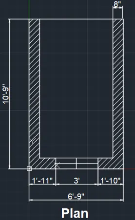
4) create the boundary region using the boundary cmt
5) then extrude its upward at the height 40'10"
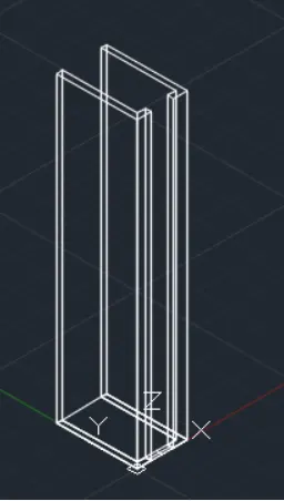
6) create the window at it required position
7) convert the figure to shaded view
8) draw the rectangle at window position and convert boundary region
9) then extrude it complete the 3d wall
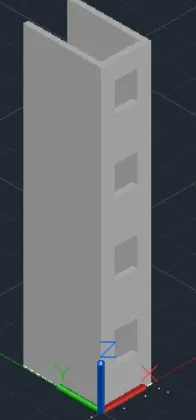
10) now hide the text and dimension and continue
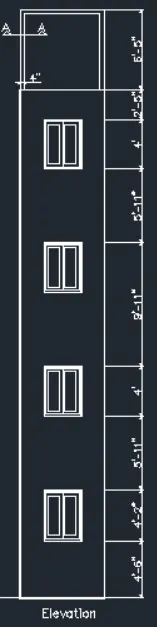
11) using the cmt rotate 3d bring that window to front view
12) now place these windows in front
13) now provide the dimension
14) section A is developed
13) now assign the layer in the different components
14) change the view shade
15) hence isometric view is created
3.AIM:
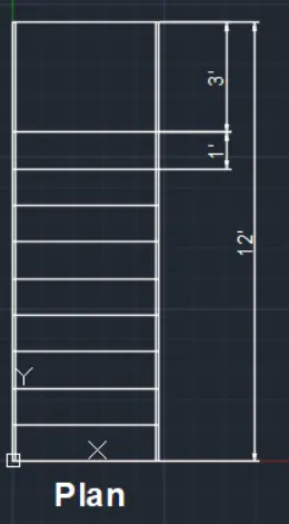
Create the ismoteric 3d view of a stair with railing as shown in the plan and elevation. Assume the size of the balustrades and the hand rails.
1) Initially using the cmt create the stair case
2) then provide necessary dimension and texts
3) move the front view and create the side elevation of stair case
4) this done using the line cmt
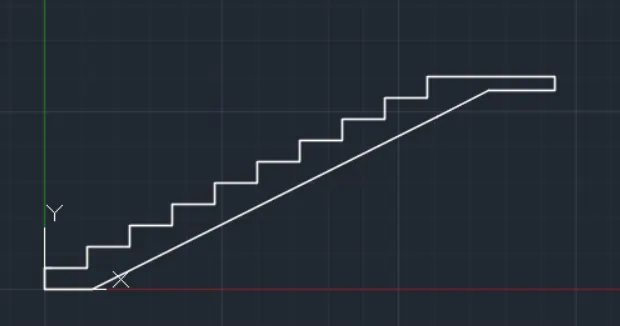
5) this portion change to aregion
6) then extude it at distance of 4'
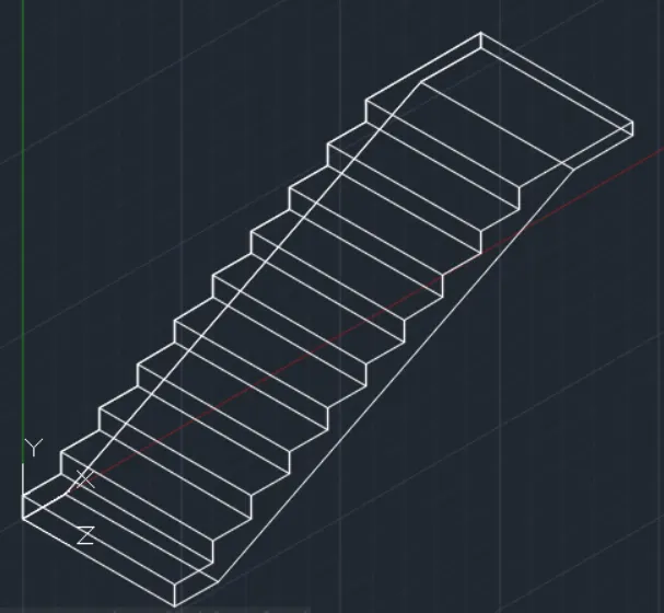
7) the balustrade is created using the circle of radius which extrude upwards at the height of 3'
8) provide text and dimension
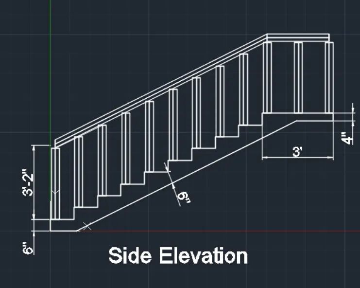
9) we have develope the isometric view of staircase
10) we have first hide dimension and text
11) then change to south west view
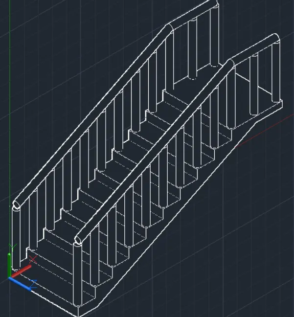
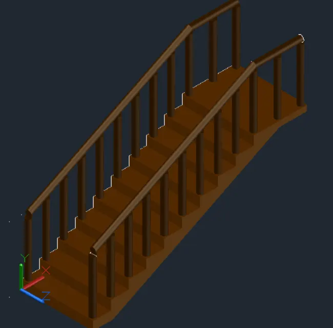
12) assign the layer to their stair case
13) hence the isometrc view is created
4.AIM:
Create the 3D view of a Wall with spread footing . Create the Door opening only. Assume the size of the parpaet and the coping. See the plans and elevation for the details. Also, create a rendered view of the model with materials as of your choice.
PROCEDURE:
1) now, go to front view and create the section of wall footing
2) using the line cmt draw the section given below
3) then provide the hatch using hatch cmt
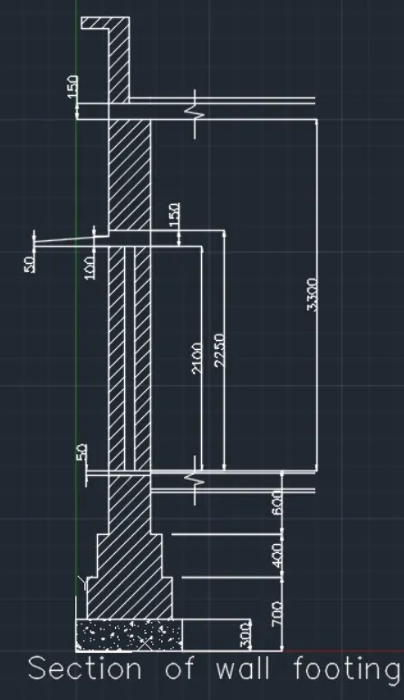
4) after creating the section go to the top view and create the plan
5) then provide dimension to complete the plan
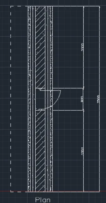
6) now create the boundary region using the bo cmt
7) then extrude the created region to a extrusion heght of 7500mm
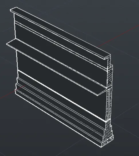
8)now, go to visualise tab of the ribbon choose the material browers and assign the materials
9) after seeing materials the output obtained
10) now we have create the door opening
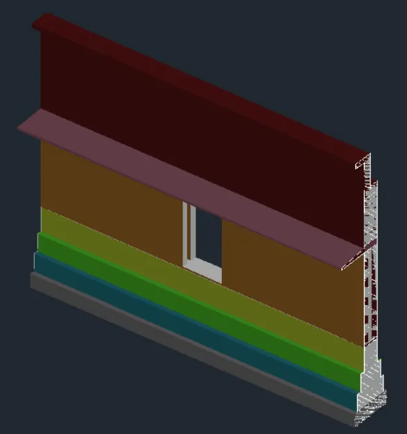
11) for this go to visualise tab and ribbon and its choose render to size option
12) the rendered image is obtained
13) hence compeleted