Creating 3D Isometric view of various structural elements in AutoCAD
1)
Aim:
Create a 3D Isometric View of the building with plan and elevation given.
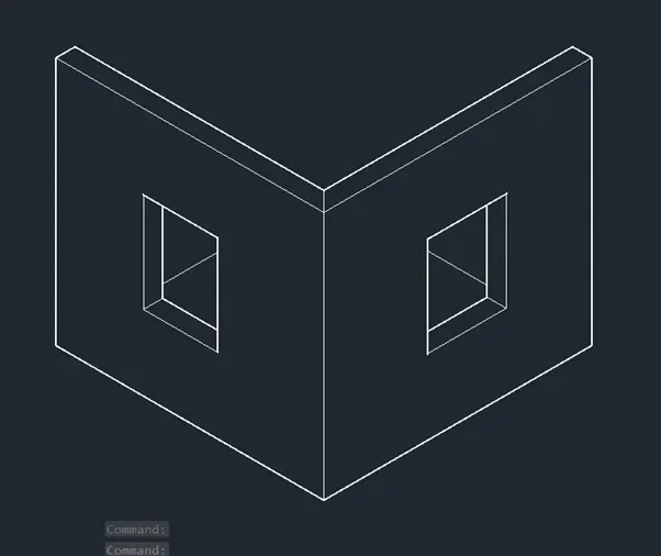
I. In command prompt type (startup:1)
II. Then file>new
III. Then create new drawing window select metric in default settings
IV. In advanced setup in units check on the architectural, angle in degrees, then ok
V. In command prompt type (L) where line command is woken
VI. In command prompt type (specify first point: 0,0,0)
VII. In command prompt type (next point: @10’9",0,0)
VIII. In command prompt type (next point: @0,3’6”,0)
IX. In command prompt type (next point: @0,3’,0)
X. In command prompt type (next point: @0,4’3”,0)
XI. In command prompt type (next point: @-4’2”,0,0)
XII. In command prompt type (next point: @-3’2”,0,0)
XIII. In command prompt type (next point: @-3’5”,0,0)
XIV. In command prompt type (next point: @0, -10’9”,0)
XV. In command prompt type (o) offset and specify the distance as the 9”
XVI. And select exterior lines that has to be offset
XVII. Tr trim al the unwanted lines
XVIII. Type bo in the command prompt and pick the boundary that at has to be region
XIX. Type EXT in command prompt and wake up the extrude command
XX. Select all the regions that has to be extruded for the 10’
XXI. And move the cursor in the required direction and specify the extrude distance as the 10’
XXII. enter
XXIII. Now, Type EXT in command prompt and wake up the extrude command
XXIV. Select all the regions that has to be extruded below the window
XXV. And move the cursor in the required direction and specify the extrude distance as the 3’
XXVI. Enter
XXVII. Now draw a rectangle near the both window and make it as the region using the region command
XXVIII. Move the region by specifying the corner as the base point @0,0,4’
XXIX. Now, Type EXT in command prompt and wake up the extrude command
XXX. Select all the regions that has to be extruded above the window
XXXI. And move the cursor in the required direction and specify the extrude distance as the 3’
XXXII. Enter
XXXIII. In command prompt type UNI and wake the union command and select the all objects and combine them
XXXIV. Enter
Result :
Required 3d structure with the reference of the section and plan view.
2)
Aim:
3D View of the Building Façade as given in the plan and elevation.
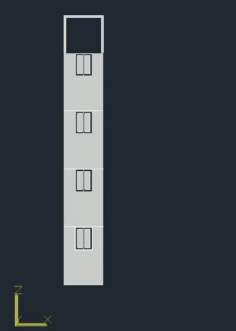
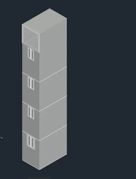
I. In command prompt type (startup:1)
II. Then file>new
III. Then create new drawing window select metric in default settings
IV. In advanced setup in units check on the architectural, angle in degrees, then ok
V. In command prompt type (L) where line command is woken
VI. In command prompt type (specify first point: 0,0,0)
VII. In command prompt type (next point: @1’11",0,0)
VIII. In command prompt type (next point: @3’,0,0)
IX. In command prompt type (next point: @1’11",0,0)
X. In command prompt type (next point: @0,10’9",0)
XI. In command prompt type (next point: @-6’9",0,0)
XII. In command prompt type (next point: @0,-10’9",0)
XIII. Offset required exterior lines by the 9” and trim unwanted lines
XIV. Join the lines near the window
XV. With the 3dface command pick the points to make the face
XVI. Totally 5 faces are created
XVII. Type EXT in command prompt and wake up the extrude command
XVIII. Select all the regions expect the window region
XIX. And move the cursor in the required direction and specify the extrude distance as the 9’11”
XX. Enter
XXI. Copy the region of the window to @0,0,5’11”
XXII. Type EXT in command prompt and wake up the extrude command
XXIII. Select the window regions that has to be extruded for the 5’11”
XXIV. And move the cursor in the required direction and specify the extrude distance as the 5’11”
XXV. Enter
XXVI. Draw the face of the window with the help of the copy and line command
XXVII. And extrude the window to the 9” on the y axis direction
XXVIII. Type co in command prompt and select all the objects
XXIX. Specify the bottom corner as the base point and
XXX. Copy the all object to the top copy point repeat this step for the other 2 times
XXXI. In command prompt type (L) where line command is woken
XXXII. In command prompt type (specify first point: using the curser as the top corner)
XXXIII. In command prompt type (next point: @4",0,0)
XXXIV. In command prompt type (next point: @0,0,6’1")
XXXV. In command prompt type (next point: @6’1”,0,0)
XXXVI. In command prompt type (next point: @0,0,-6’1”)
XXXVII. In command prompt type (next point: @4",0,0)
XXXVIII. In command prompt type (next point: @0,0,6’5”)
XXXIX. In command prompt type (next point: @-6’9",0,0)
XL. In command prompt type (next point: @0,0,-6’5”)
XLI. Create the 3dface for the 3 boundary
XLII. With the help of the extrude tool extrude the 3 regions for 10’9” along the y axis
XLIII. In command prompt type UNI and wake the union command and select the all objects and combine them
XLIV. Enter
Result:
3d section on the basis of the plan and section was drawn in the AutoCAD 3d.
3)
Aim:
isometric 3d view of a stair with railing as shown in the plan and elevation
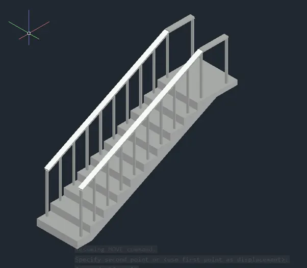
I. In command prompt type (startup:1)
II. Then file>new
III. Then create new drawing window select metric in default settings
IV. In advanced setup in units check on the architectural, angle in degrees, then ok
V. In command prompt type (L) where line command is woken
VI. In command prompt type (specify first point: 0,0,0)
VII. In command prompt type (next point: @0,0,6”)
VIII. In command prompt type (next point: @1’,0,0)
IX. Select the both the lines created and type CO in the command prompt and
X. Specify the base point as the bottom corner and copy it to the top corner
XI. Repeat this step for the other 8times
XII. Now using the snapping option draw the line connecting the bottom corner and the top corner
XIII. Now type o in the command prompt and offset the line by 6”
XIV. And delete the previously created line
XV. Draw a other straight line form the bottom corner intersecting the inclined line
XVI. With the fillet option join both the lines
XVII. At the top corner draw a line @3’,0,0
XVIII. And offset this line to 4” downwards
XIX. Again, use the fillet tool and join both the lines
XX. Using the region command select all the objects and create the region
XXI. Type EXT in command prompt and wake up the extrude command
XXII. Select the regions that has to be extruded
XXIII. And move the cursor in the y direction and specify the extrude distance as the 3’
XXIV. Enter
XXV. Using the circle command create the circle over the first step
XXVI. Create this circle as the region
XXVII. Type EXT in command prompt and wake up the extrude command
XXVIII. Select the circle regions that has to be extruded
XXIX. And move the cursor in the z direction and specify the extrude distance as the 3’
XXX. Enter
XXXI. Now copy the rail and specify the base point as the stairs corner
XXXII. And copy it to every stair
XXXIII. At the landing copy it at the midpoint and end point
XXXIV. Draw a 2-polyline connecting all the rails on the stair and landing
XXXV. At the end of the polyline draw the rectangle in the xz plane of the 2” height
XXXVI. Select the sweep command
XXXVII. Select the rectangle as the object
XXXVIII. And polyline connected to the rails as the path for the sweep
XXXIX. Enter
XL. Now sweep is created
XLI. Now, type CO in command prompt and to copy
XLII. Now select all the rails and the sweep
XLIII. Specify the base point as the bottom connection to stair and copy to the other side of the stair
XLIV. Enter
Result:
3d model of the staircase is one in the AutoCAD 3D
4)
Aim:
3D view of a Wall with spread footing. And the Door opening only. Assumed the size of the parapet and the coping. See the plans and elevation for the details. and rendered view of the model with materials
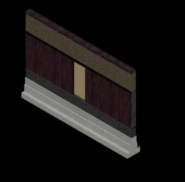
I. In command prompt type (startup:1)
II. Then file>new
III. Then create new drawing window select metric in default settings
IV. In advanced setup in units check on the decimal, angle in degrees, then ok
V. In the material browser load the all materials
VI. In command prompt type (L) where line command is woken
VII. In command prompt type (specify first point: 0,0,0)
VIII. In command prompt type (next point: @900,0,0)
IX. In command prompt type (next point: @0,3300,0)
X. In command prompt type (next point: @0,900,0)
XI. In command prompt type (next point: @0,3300,0)
XII. In command prompt type (next point: @900,0,0)
XIII. In command prompt type (next point: @0,7500,0)
XIV. Next, Offset the vertical line to right by 200
XV. Next, Offset the vertical line to right by 50
XVI. Next, Offset the vertical line to right by 50
XVII. Next, Offset the vertical line to right by 300
XVIII. Next, Offset the vertical line to right by 50
XIX. Next, Offset the vertical line to right by 50
XX. Next, Offset the vertical line to right by 200
XXI. Draw a rectangle of 7500*300 and move it to the @0,0,4950
XXII. Select this rectangle and make it region and thenType ext in the command prompt
XXIII. Extrude it in the z direction by 150
XXIV. Assign the material non uniform rail
XXV. Draw a rectangle of 7500*300 and move it to the @0,0,3950
XXVI. Select this rectangle and make it region and thenType ext in the command prompt
XXVII. Extrude it in the z direction by 1000
XXVIII. Assign the material clinker
XXIX. Draw a rectangle of 7500*300 and move it to the @0,0,3800
XXX. Select this rectangle and make it region and thenType ext in the command prompt
XXXI. Extrude it in the z direction by 150
XXXII. Assign the material handrails and railings
XXXIII. Draw a rectangle of 7500*300 and move it to the @0,0,1700
XXXIV. Select this rectangle and make it region and thenType ext in the command prompt
XXXV. Extrude it in the z direction by 2100
XXXVI. Assign the material non-uniform soldier
XXXVII. Draw a rectangle of 7500*300 and move it to the @0,0,1650
XXXVIII. Select this rectangle and make it region and thenType ext in the command prompt
XXXIX. Extrude it in the z direction by 50
XL. Assign the material metal
XLI. Draw a rectangle of 7500*300 and move it to the @0,0,1100
XLII. Select this rectangle and make it region and thenType ext in the command prompt
XLIII. Extrude it in the z direction by 550
XLIV. Assign the material exposed aggregate
XLV. Draw a rectangle of 7500*400 and move it to the @0,0,700
XLVI. Select this rectangle and make it region and thenType ext in the command prompt
XLVII. Extrude it in the z direction by 400
XLVIII. Assign the material fine alabaster
XLIX. Draw a rectangle of 7500*500 and move it to the @0,0,300
L. Select this rectangle and make it region and thenType ext in the command prompt
LI. Extrude it in the z direction by 400
LII. Assign the material course polished alabaster
LIII. Draw a rectangle of 7500*900 and move it to the @0,0,0
LIV. Select this rectangle and make it region and thenType ext in the command prompt
LV. Extrude it in the z direction by 300
LVI. Assign the material course polished alabaster
LVII. Create the rectangle of the 300*900 in xy plane
LVIII. Select this rectangle and make it region and thenType ext in the command prompt
LIX. And extrude it for 2100 in z direction
LX. And the copy it to by specify the bottom corner as the base popint copy it to (300,3300,1700)
LXI. Assign the material ash door
LXII. Subtract the box from the footing wall and again copy the door
LXIII. Enter
LXIV. Go to visualize toolbar and in the render select medium
LXV. And render window dimension
LXVI. And select the view that has to be rendered on screen
LXVII. Type rr in the command prompt and wake the render command
LXVIII. Therefore, we obtain the rendered model in the render window.
Result:
Rendered model is obtained in the AutoCAD 3D