Creating 1D Connectors for the given Frame component using Hypermesh
Aim:
Meshing and Creating connectors in various parts of the given model using Hypermesh as per the specifications given below:
1. Right_Rail_2 & Front_truss_1:- Seam-Quad(angled+capped+L).
2. Left_Rail_2 & Front_truss_1:- Quad elements.
3. Front_truss_2, Front_truss_1 & Right_Rail_1:- Spot weld with 3 Layers and 5 mm Diameter.
4. Front_truss_2, Front_truss_1 & Left_Rail_1:- Hexa (Adhesive).
5. Rear_truss_2 & Right_Rail_2:- Bolt Connector.
6. Rear_truss_2 & Left_Rail_2:- Bolt Connector.
7. Right_Rail_1 & Right_Rail_2:- Spot-weld with Rigid Elements.
8. Left_Rail_1 & Left_Rail_2:- Spot-weld with Spring Elements.
9. Rest all the component left Join them with suitable connectors.
Procedure:
1) We first import the frame assembly model in hypermesh using the Import option.
2) We can see that the model has already been mid-surfaced as shown in the image given below.
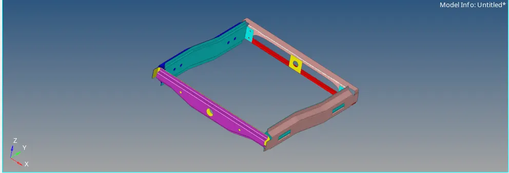
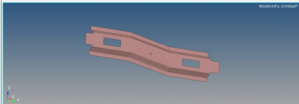
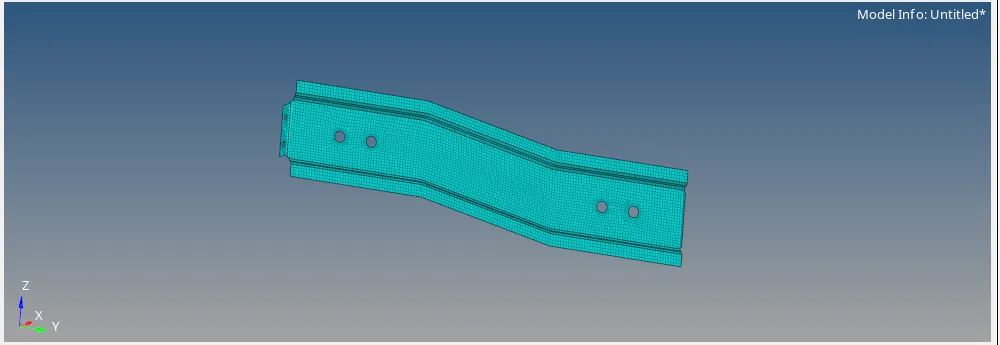
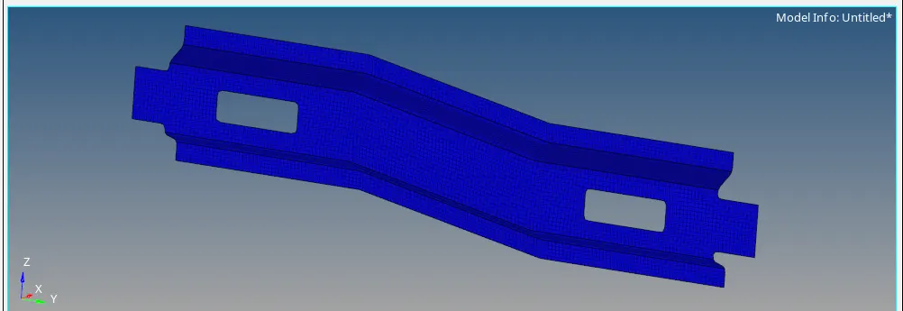
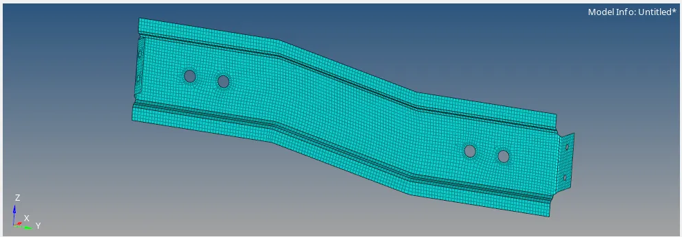
3) We proceed to mesh all the components using the target element length = 5 mm.
4) We have meshed the components part by part using the automesh option in the 2D module as shown in the image given below.

5) The meshed components are shown in the images given below.
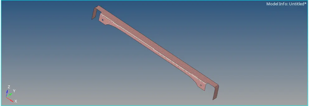
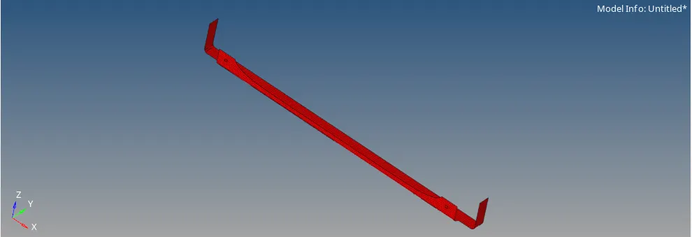
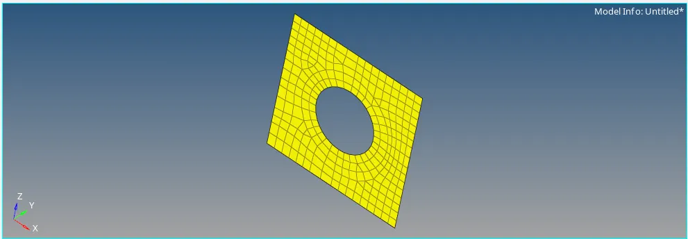
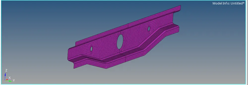
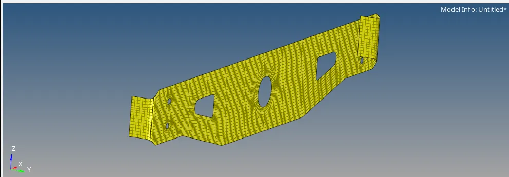
6) Then we start connectors part for that we go to the 1D module and select the respective connectors.
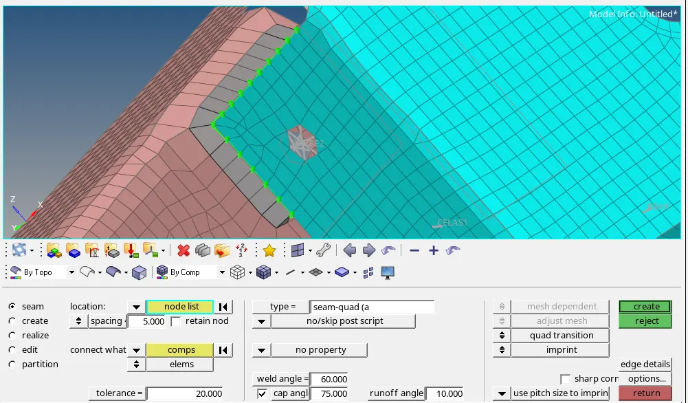
1. Right_Rail_2 & Front_truss_1:- Seam-Quad(angled+capped+L).
1) We hide the rest of the surfaces and we keep only Right_Rail_2 & Front_truss_1.
2) We go to connectors option in the 1D module and we go to seam option. In it we, select the location, where the Weld has to be created, by clicking the “node list” then, we select the “comps” option under “connect what”, in order to create the weld between those two components. Then, we specify the “tolerance” value, based on the distance between the two components and we select the type as “seam-quad (angled+capped+L)”. Then, we click on create option which realizes the weld connection as shown in the image given below.
2. Left_Rail_2 & Front_truss_1:- Quad elements.
1) We hide the rest of the surfaces and we keep only Left_Rail_2 & Front_truss_1.
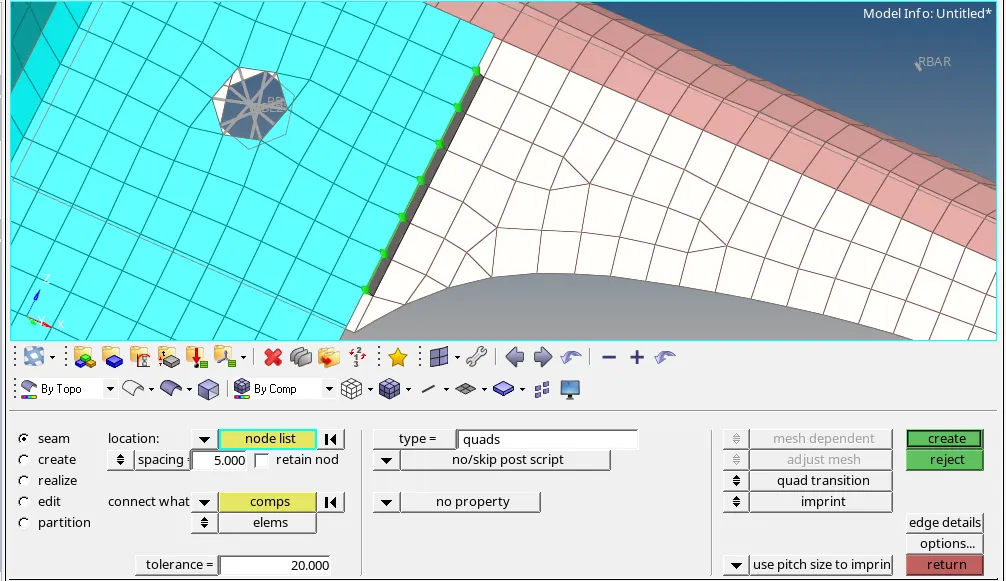
2) We go to connectors option in the 1D module and we go to seam option. In it we, select the location, where the Weld has to be created, by clicking the “node list” then, we select the “comps” option under “connect what”, in order to create the weld between those two components. Then, we specify the “tolerance” value, based on the distance between the two components and we select the type as “quads”. Then, we click on create option which realizes the weld connection as shown in the image given below.
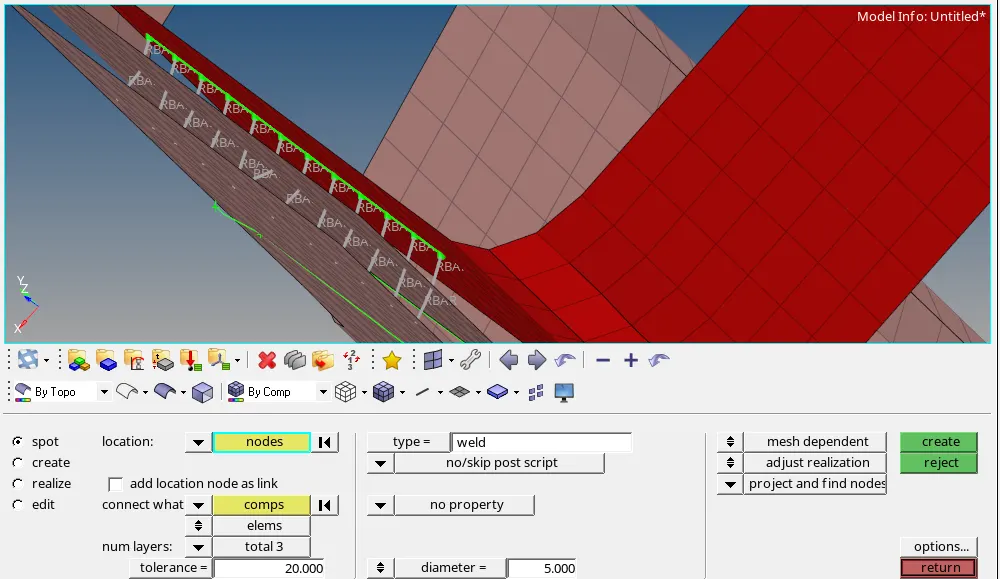
3. Front_truss_2, Front_truss_1 & Right_Rail_1:- Spot weld with 3 Layers and 5 mm Diameter.
1) We hide the rest of the surfaces and we keep only Front_truss_2, Front_truss_1 & Right_Rail_1.
2) We go to connectors option in the 1D module and we go to spot option. In it we, select the location, where the Weld has to be created, by clicking the “node list” then, we select the “comps” option under “connect what”, in order to create the weld between those three components. Then, we specify the “tolerance” ,"No of Layers" and " Diameter" values, based on the data given in the aim and we select the type as “weld”. Then, we click on create option which realizes the weld connection as shown in the image given below.
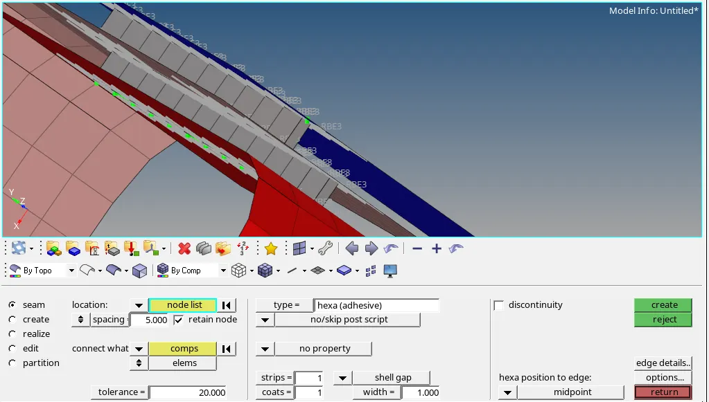
4. Front_truss_2, Front_truss_1 & Left_Rail_1:- Hexa (Adhesive).
1) We hide the rest of the surfaces and we keep only Front_truss_2, Front_truss_1 & Left_Rail_1.
2) We go to connectors option in the 1D module and we go to seam option. In it we, select the location, where the adhesive has to be created, by clicking the “node list” then, we select the “comps” option under “connect what”, in order to create the adhesive between those two components. Then, we specify the “tolerance” value, based on the distance between the two components and we select the type as “Hexa(adhesive)”. Then, we click on create option which realizes the weld connection as shown in the image given below.
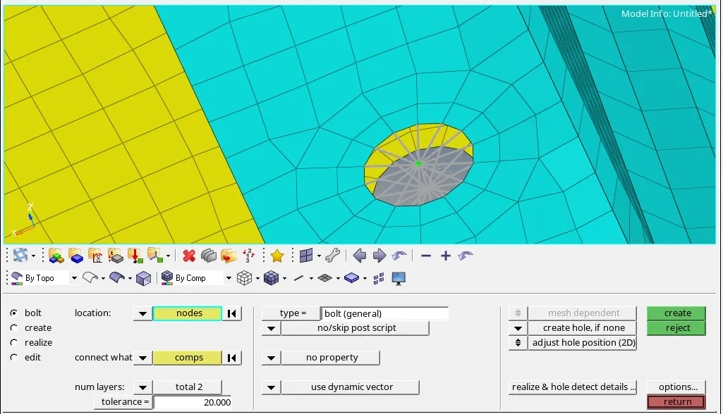
5 & 6. Rear_truss_2 & Right_Rail_2 and Rear_truss_2 & Left_Rail_2:- Bolt Connector.
1) We hide the rest of the surfaces and we keep only Rear_truss_2 & Right_Rail_2 and Rear_truss_2 & Left_Rail_2.
2) We go to connectors option in the 1D module and we go to bolt option. In it we, select the location, where the bolt has to be created, by clicking the “node” then, we select the “comps” option under “connect what”, in order to create the bolt between those two components. Then, we specify the “tolerance” value, based on the distance between the two components and we select the type as “Bolt(General)”. Then, we click on create option which realizes the weld connection as shown in the image given below.
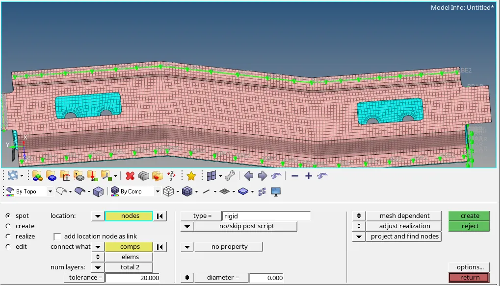
7. Right_Rail_1 & Right_Rail_2:- Spot-weld with Rigid Elements.
1) We hide the rest of the surfaces and we keep only Right_Rail_1 & Right_Rail_2.
2) We go to connectors option in the 1D module and we go to spot option. In it we, select the location, where the weld has to be created, by clicking the “node” then, we select the “comps” option under “connect what”, in order to create the weld between those two components. Then, we specify the “tolerance” value, based on the distance between the two components and we select the type as “rigid”. Then, we click on create option which realizes the weld connection as shown in the image given below.
8. Left_Rail_1 & Left_Rail_2:- Spot-weld with Spring Elements.
1) We hide the rest of the surfaces and we keep only Left_Rail_1 & Left_Rail_2.
2) We go to connectors option in the 1D module and we go to spot option. In it we, select the location, where the weld has to be created, by clicking the “node” then, we select the “comps” option under “connect what”, in order to create the weld between those two components. Then, we specify the “tolerance” value, based on the distance between the two components and we select the type as “spring”. Then, we click on create option which realizes the weld connection as shown in the image given below.
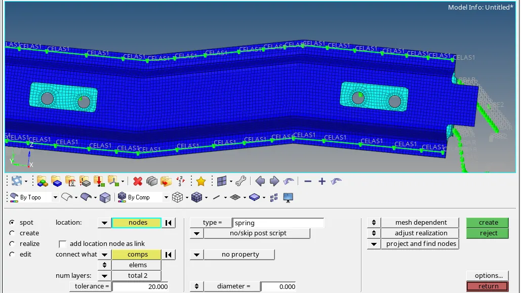
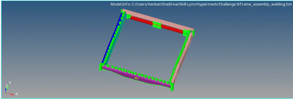
7) Rest all components were connected with spotwelds, seam welds and bolt connections. The fully connected model is shown in the image given below.
Conclusion:
1) We have meshed the given frame assembly component part by part.
2) We have also used connectors such as spotwelds, seam welds, adhesives and bolt connections as for various parts of the components as given in the aim.
3) We have finally obtained the fully connected models.