Creating 1-D elements for the given component using Hypermesh
Aim:
1) To take mid surface for the given component.
2) To mesh the mid surfaced components.
3) To create 1D elements with the given crossections and DOF.
a. Rod element:- with only translational DOF and RBE2 link
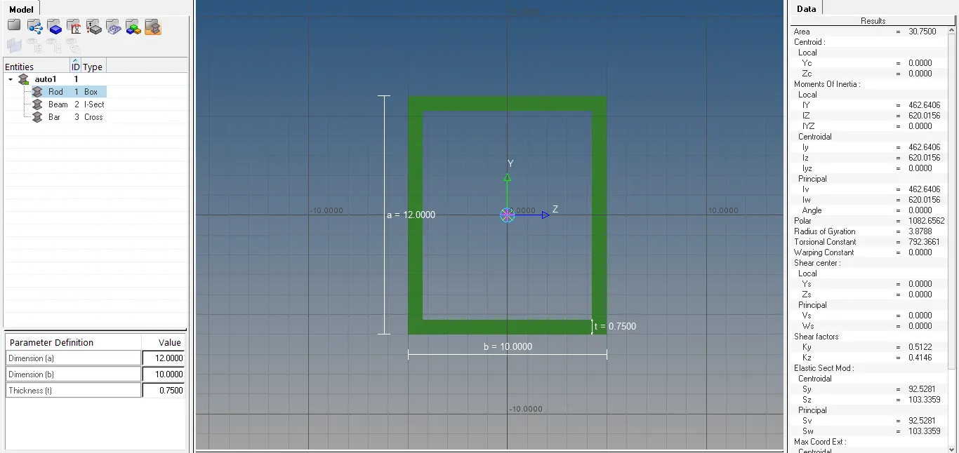
Cross-Section: BOX- Dimension a= 12 mm
Dimension b=10 mm
Thickness t= 0.75 mm
b. Beam element:- with all DOF and RBE3 link
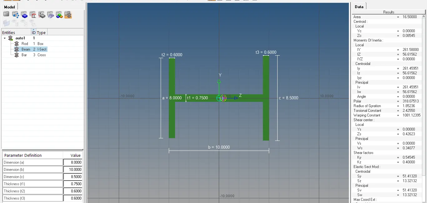
Cross-Section: I Section- Dimension a= 8 mm
Dimension b= 10 mm
Dimension c= 8.5 mm
Thickness t1= 0.75 mm
Thickness t2= .6 mm
Thickness t3= .6 mm
c. Bar element:- with only x and y DOFs With RBE3 link
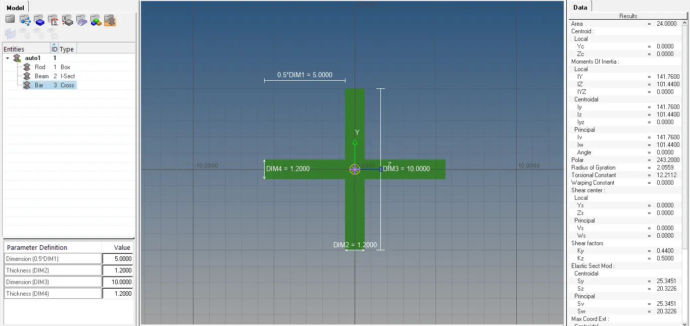
Cross-section: CROSS section- Dimension DIM1= 5 mm
Thickness DIM2= 1.2 mm
Dimension DIM3= 10 mm
Thickness DIM4= 1.2mm
d. & e. apply the mass of magnitude 10 with RBE2 link.
f. Join the two components with Spring elements.
Theory:
1-D elements:
We use 1-D elements when one of the dimension is very large compared to other two dimensions. The types of 1-D elements are rod, bar, beam etc. The practical application of 1-D elements are Long shafts, beams, pipe joints, connection elements.
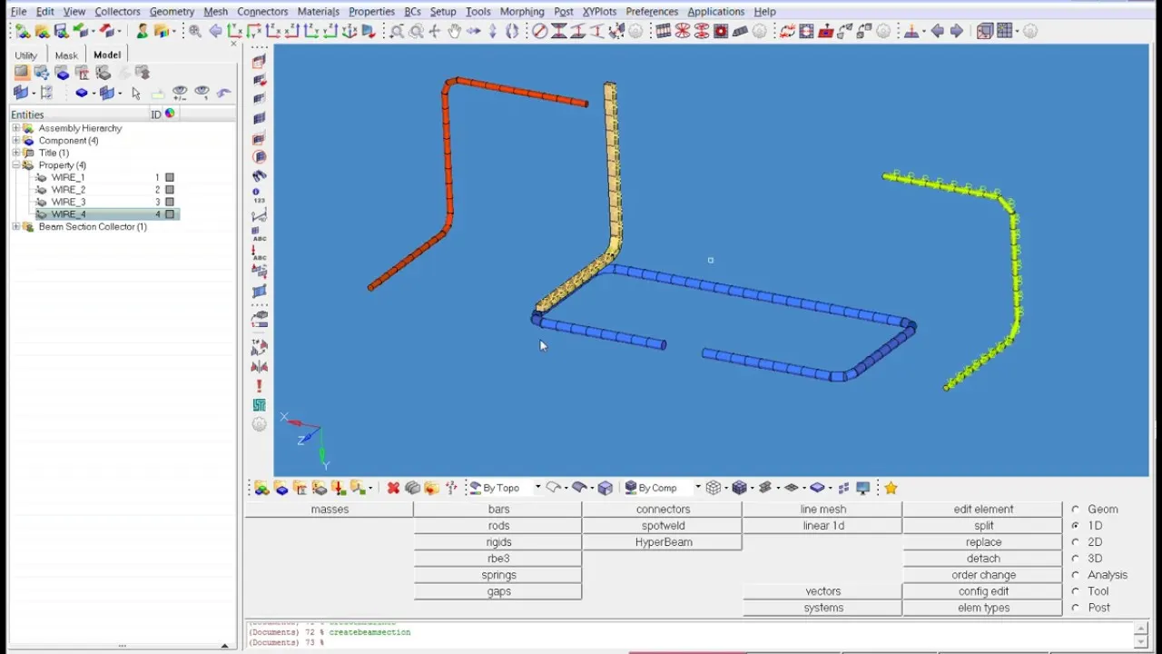
The Rods/Bars are any member which are subjected to axial (Tensile/Compressive but no Transverse/Torsional loads) Loads only. But rods are definitely circular cross section whereas Bars are of can be non-circular cross section.
The Beams are subjected Transverse (no Torsional loads) loads in addition to Axial loads (if required). The cross section of the beam can be circular/non-circular.
Procedure:
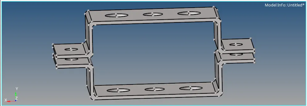
1) We import the model using the import option. We can see that the component is a double sided bracket as shown in the image given below.
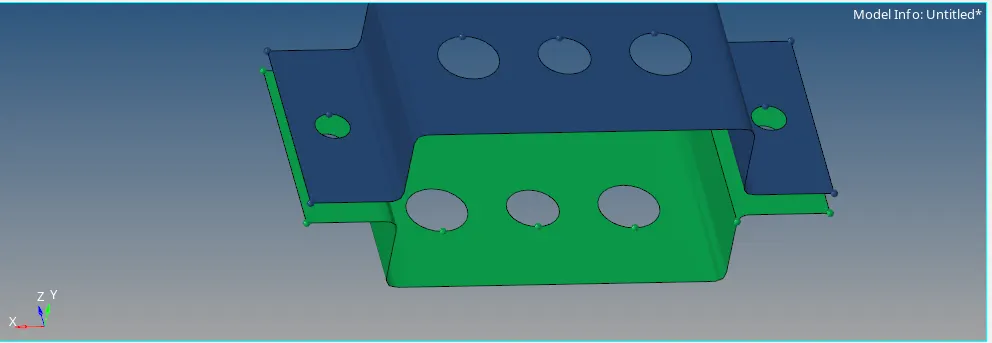
2) We then, measure the thickness of the component using the distance option and take the mid surface using the mid surface option in the geometry module as shown in the image given below.
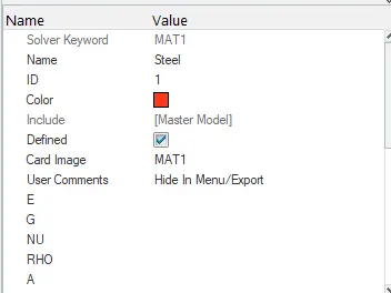
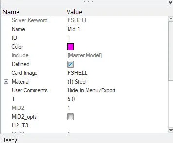
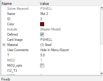
3) We assign material and properties to the midsurfaced component using the create option by right clicking on the model browser as shown in the images given.
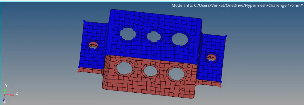
4) We then, proceed to mesh the component using the automesh option in the 2-D module and we specify the target element length =8mm then, we create washer splits for the holes provided to us. Finally, we again try to rebuild the mesh and we get a good mesh flow as shown in the image given below.
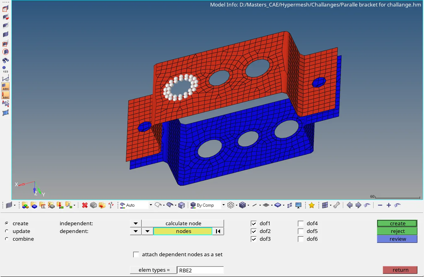
5) We then, proceed to create the 1D elements i.e. RBE2, RBE3, CBAR, CBEAM, CMASS & CROD. For that, first we create RBE2 elements using the rigids present in the 1D module for the first set of holes top and bottom and we also restrict the element to translational DOF in X, Y and Z axis as shown in the image given below.
6) We then, create RBE3 elements using the RBE3 option in the 1D module for the second set of holes top and bottom and we also restrict the element to all DOF in X, Y and Z axis as shown in the image given below.
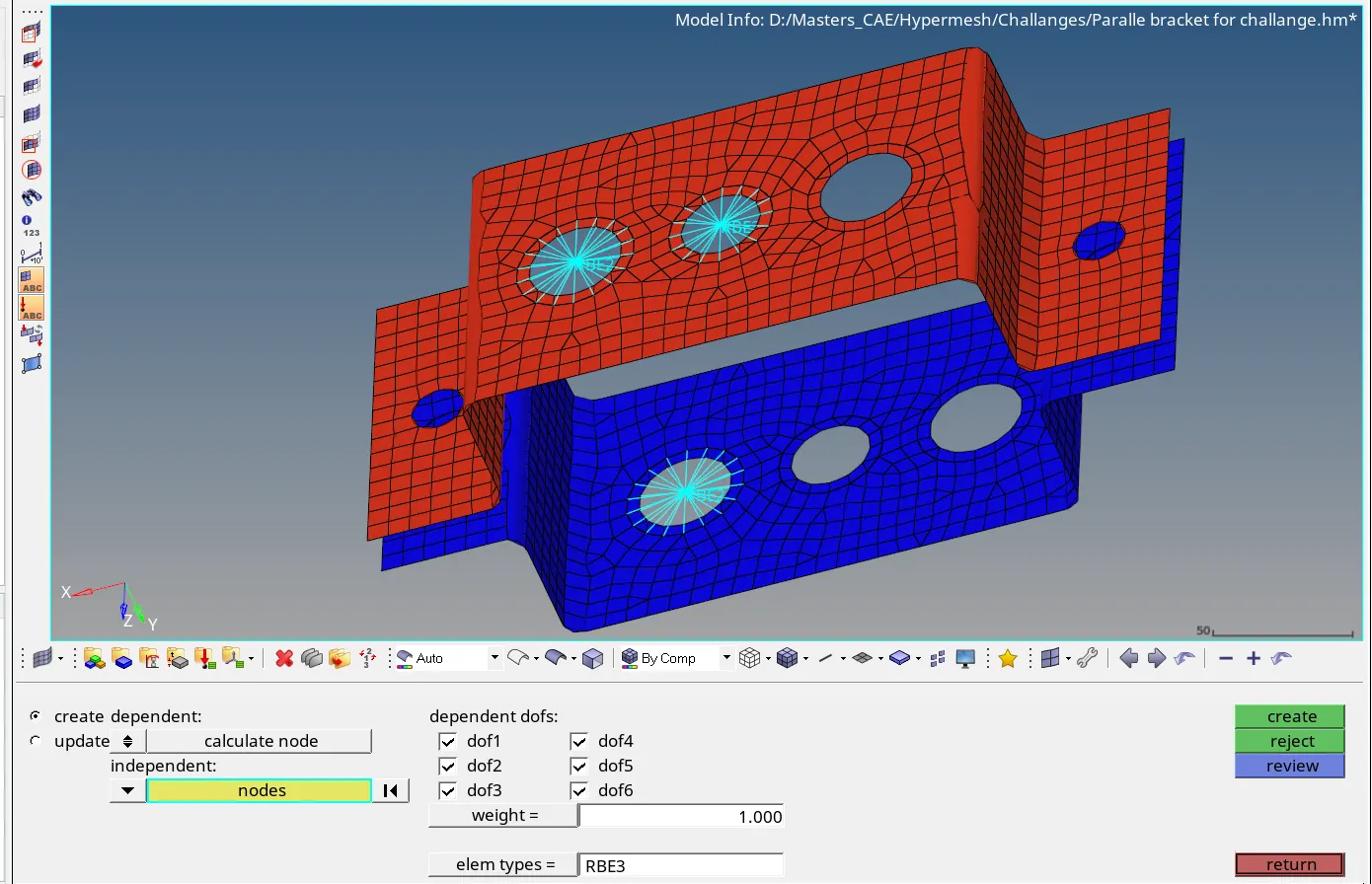
7) We then, again create RBE3 elements using the RBE3 option in the 1D module for the third set of holes top and bottom and we also restrict the element to translation and rotation DOF in X and Y axis as shown in the image given below.
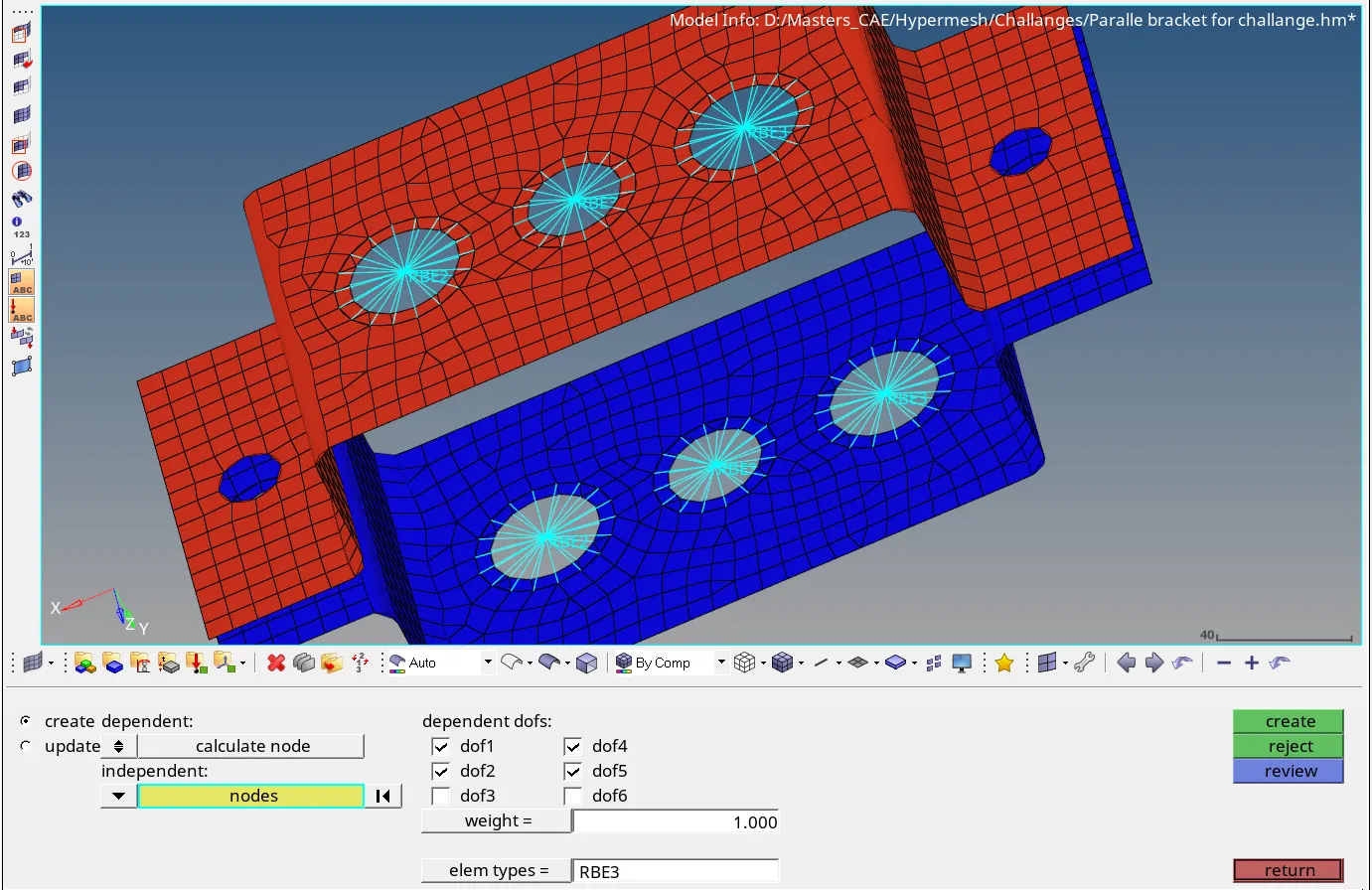
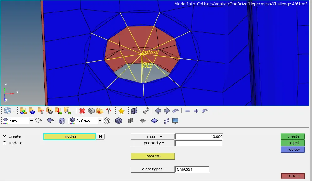
8) We proceed to give RBE2 elements on the holes on the either of sides of the bracket both in top and bottom components. After that, we join the top and bottom master nodes using an RBE2, then we create a mass using the masses option in the 1-D module and we provide the mass of magnitude 10 and type of mass as CMass as shown in the image given below.
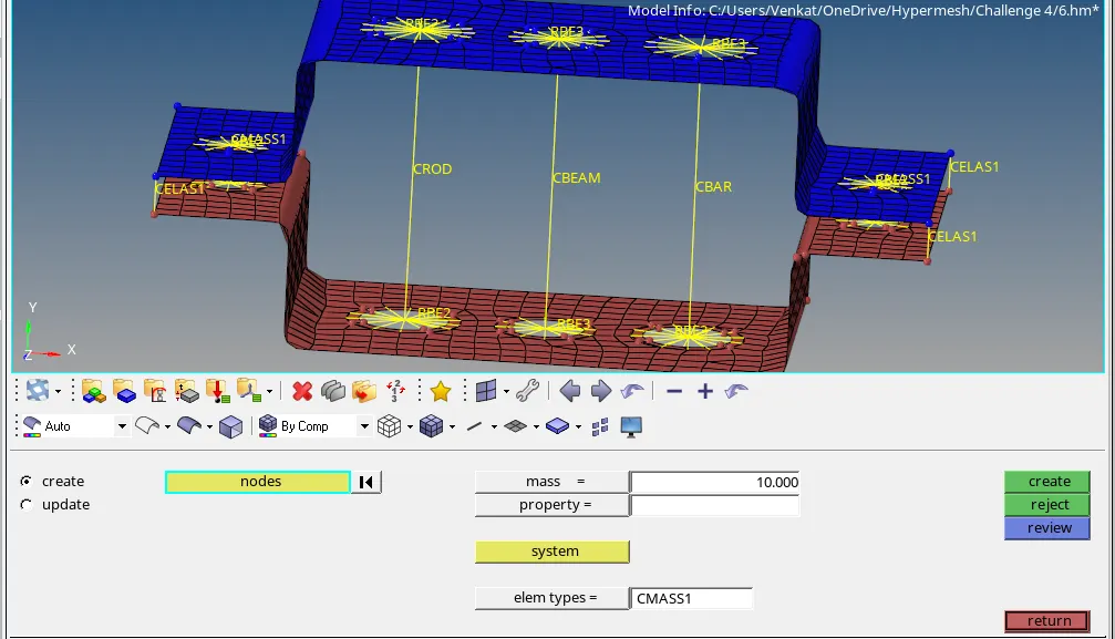
9) We then, create CBAR, CBEAM and CROD with the master nodes of all the opposite holes in the 1D module as shown in the image given below.
10) We then, create cross-sections using the Hyperbeam for rod, beam and bar. First, we create cross section using the given dimensions in the aim for Rod that is a thinwall box as shown in the image given below.
11) We create the second cross section using the given dimensions in the aim for Beam that is a I beam as shown in the image given below.
12) We create the final cross section using the given dimensions in the aim for Bar that is a Cross option in the optistruct sections as shown in the image given below.
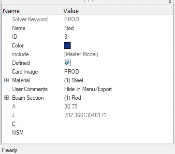
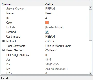
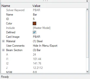
13) After that we create properties by right clicking on the property tree for the Rod, Beam and Bar with property cards as PROD, PBEAM and PBAR. The properties created as shown in the image given below.
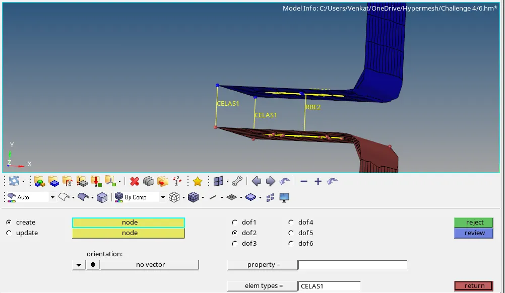
14) Then, finally we create spring elements using the springs option under the 1D module. In that we give the type of spring as CELAS and we constrain the Y axis Translation as shown in the image given below.
Conclusion:
1) We have imported the model and we taken the mid-surface of the components and we assigned material and property to the mid surfaced components.
2) We have meshed the components and then, we have connected the holes of the components with RBE2 and RBE3 elements.
3) We have created the CBAR, CBEAM & CROD 1D elements with their DOF constrained according to the data given in the aim.
4) We have also created cross-sections for the rod, beam and bar using the hyperbeam option and we also created material and property cards for the rod, beam and bar i.e. PROD, PBEAM and PBAR.
5) We also have created a mass i.e. CMASS in the holes on either having RBE2 connections.
6) Finally, we also created CELAS type spring on four edges of both components.