Control Logic of Washing Machine and Gear Shift Logic of an Automobile using Stateflow in Simulink
Aim:
1) Implementing control logic of a “washing machine” using Stateflow as per given sequence:
- If the power supply is available, the system gets activated
- If the Water supply is not available, stop the process & indicate through LED
- Soaking time should be 200s followed by Washing time of 100s.
- Then rinsing happens for next 20s & dryer runs for 50s
After all the processes have completed the the finished LED is turned on
2) Making a Simulink chart for the “Gear shift” logic as per below conditions:
Speed Range(kmph) Gear
0 to 15 1
16 to 25 2
26 to 40 3
41 to 60 4
Above 61 5
Giving speed input while the simulation is running & display the gear number.
Theory:
Working of a Washing Machine:
The working principle of a washing machine is centrifugation. Centrifugation is a separation process which uses the action of centrifugal force to promote accelerated settling of particles in a solid-liquid mixture. The washing machine consists of centrifuge for this purpose. A centrifuge is a piece of equipment that puts an object in rotation around a fixed axis, applying a force perpendicular to the axis of spin that can be very strong. A domestic Washing Machine works like an electromechanical system in which there are four processes namely:
1) Soaking
2) Washing
3) Rinsing
4) Spining
All the 4 processes occur according to the timing that has defaultly given in the system. When we provide the power supply the washing machine gets switched on and we also provide water supply so that the water will be used for above processes to wash the clothes.
Working of a Gear Shifting:
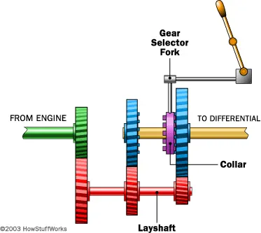
Gears are used for transmitting power from one part of a machine to another. In a bicycle, for example, it's gears (with the help of a chain) that take power from the pedals to the back wheel. Similarly, in a car, gears transmit power from the crankshaft (the rotating axle that takes power from the engine) to the driveshaft running under the car that ultimately powers the wheels. Changing gears is about using the engine's power in different ways to match changing driving conditions. The driver uses the gearshift to make the engine generate more force or more speed depending on whether hill-climbing power, acceleration from a standstill, or pure speed is needed. In practice, changing gears means meshing different sized gear wheels together, but you can't do that while the gearbox is transmitting power from the engine at high speed. That's why you need to press a car's clutch pedal before changing gears, which disengages the engine's input from the gearbox. You can then use the gearshift to change to a different pattern of gears, before letting the clutch transmit power back from the engine to the gearbox (and the wheels) once again.
Stateflow:
Stateflow provides a graphical language that includes state transition diagrams, flow charts, state transition tables, and truth tables. You can use Stateflow to describe how MATLAB algorithms and Simulink models react to input signals, events, and time-based conditions. Stateflow enables you to design and develop supervisory control, task scheduling, fault management, communication protocols, user interfaces, and hybrid systems.
Procedure:
1) Control Logic of a Washing Machine:
1) First, we open a simulink stateflow chart in the simulink environment. Then in the chart we first provide the input power supply and water supply as a flow chart. In the below image if input power and water is <1 there is zero input or no input. If the input power and water supply are >0 then there in an input porvided for running the washine machine.
2) After providing the input, we then start the processes Soaking which will last for 200 secs, Washing which will last for 100 secs, Rinsing will last for 20 secs and finally the drying process which last for 50 secs. Then the whole process is completed. Here in the image at the entry of each block we provide entry as 0 and exit as 1 since at entry there is no ongoing process and at exit there is a process which completed.
3) After finishing the process of the flow chart we name the input and output varaibles according to the order of process using the symbol pane which is situated under the prepare toolstrip.
4) We, then come out of the chart and give the inputs as constant blocks as there are only 2 inputs namely power supply and water supply. After that, we display the output using the display block which are power supply, water supply, soaking process, washing process, rinsing process, drying process and the finishing process. We then create lamps from the simulink library dashboard for all the outputs formed. Then we run the program for 400 secs and observe the that all process are completed successfully and output is displayed as green light glowing for all the process.
5) When we provide zero input for the water supply or power supply the operation is not completed as the whole process uses both water and power as a source of input if either of this is missing then the output lamp turns red.
2) Gear Shift Logic of an Automobile:
1) The second question is about the working a gear mechanism in a car and at what speeds the gear of a car is changing varying from gear 1 to 5.
2) In the question they have given the speed range in kmph for a particular gear.
3) We are first creating a simulink stateflow chart for the gear shifting as per variation in speed. In the below image, we see that we are providing varing input as speed and the gear number ius assigned for a particular speed range if the speed of the vehicle is greater than the earlier gear's speed range the gear is changed.
4) Then, we provide the inputs which is the speed varing and outputs which is the gear number using the symbols pane in prepare toolstrip.
5) We move out of the chart and then we provide a constant varing input with slider gain source as speed and we also display the output using display block which is basically the gear number. We run the program for infinite times hence we provide the stop time as inf. on running we constantly vary the input speed and corresponding gear for the speed range is displayed as the output as seen in the below images.
Conclusion:
1) We have implemented the control logic of a “washing machine” using Stateflow using the sequence provided in the aim and after finishing all the processes the LED light turns green indicating that the process is finished.
2) We have also made a Simulink chart for the “Gear shift” logic as per the information provided in the aim and for the given speed input using the slider gain block while the simulation is running, the corresponding gear number is displayed as output in the display block.