Creating connection for Rear door
TITLE: Creating connection for Rear door.
Summary: In this project, we have consider a meshed element door panel assembly. So far NVH is conserned, a door panel being an important assembly various joints , coonections has been assigned to it.
Introduction: In NVH, a door panel is an important part. In order to simulate, all desired setups & connections must be assigned properly. The bolts & welds are by far the most used connections in any automotive body.
Procedure:
1. Deploying the Connections at Hinges:
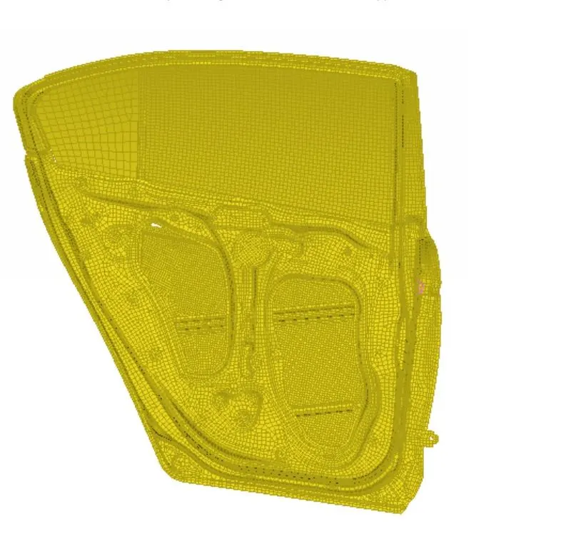
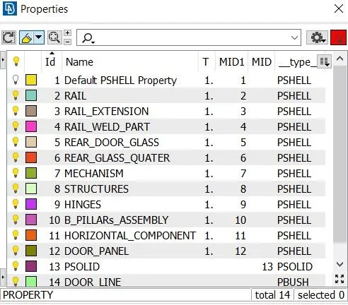
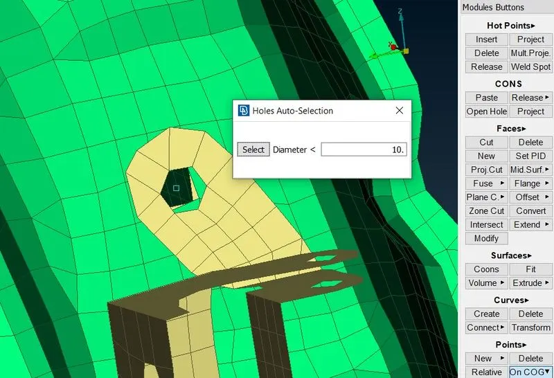
We begin with assigning the PID for each component for door panel. Initially, the connections are deployed at the hinge regions. In which hinges connects the door sub-system and the body of car. At the hinges, the bolted joint is used. Inorder to replicate, the bolted joint is created. For creating connection, A COG point is required. Which is available in "Points" from "Topo" module.
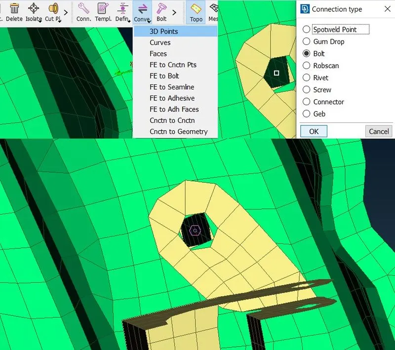 Then the created COG point should be converted to a 3D point from the "Convert" option in assembly manager. Now the 3D point should be selected and bolt option should be selected. Inorder to convert the 3D point to bolt. Then by using "connection" option from the assembly manager, the bolt should be selected. The dialog box appears. The 2 PIDs are selected representing part IDs to be joined together.
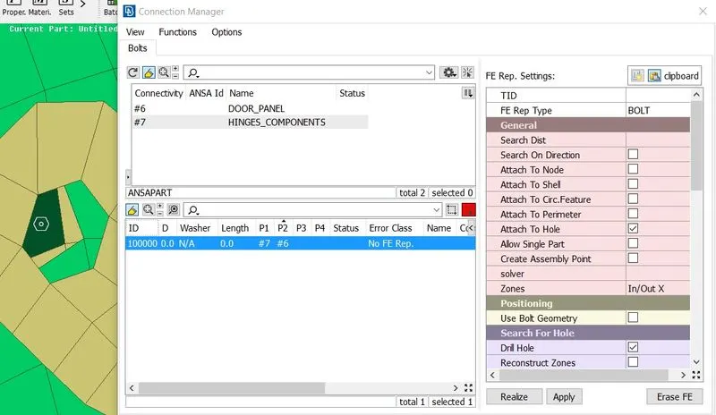
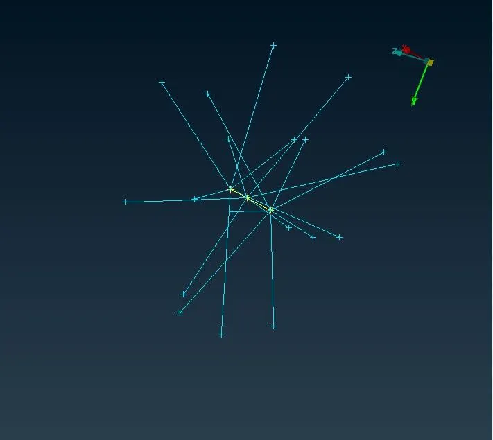
Then by middle clicking, a dialog box appears. Which represents the connection manager. Then by selecting Apply, Realize the connection will be realized. Then the connection is deployed using RBE2 cluster in some regions. In which the RBE2 element
option should be selected. RBE2 cluster means, connecting so many nodes.
Now,we select the two nodes(for Master nodes of the created RBE2 cluster), a dialog box appears. WHich represents
the info about RBE2 elements. In which CM(Degrees of freedom) should be constrained in all directions except rotation in Z-direction(CM only in 1,2,3,4,5). So that, the door will be moved in rotation with respect to Z-axis. 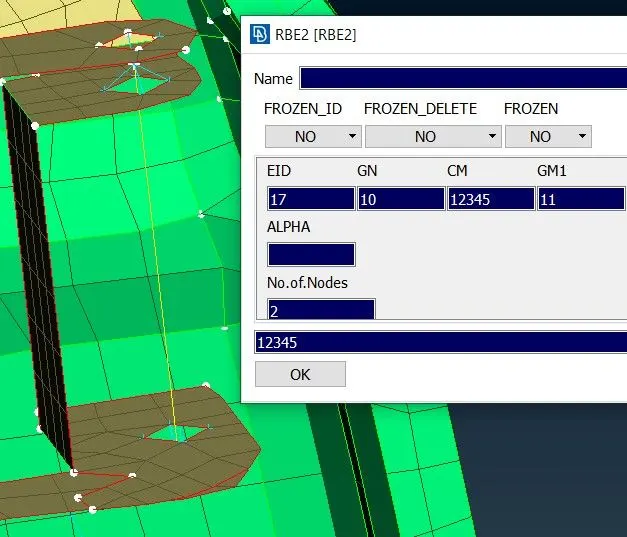
We apply RBE2 joints at all required coonctions untill we fulfill all. 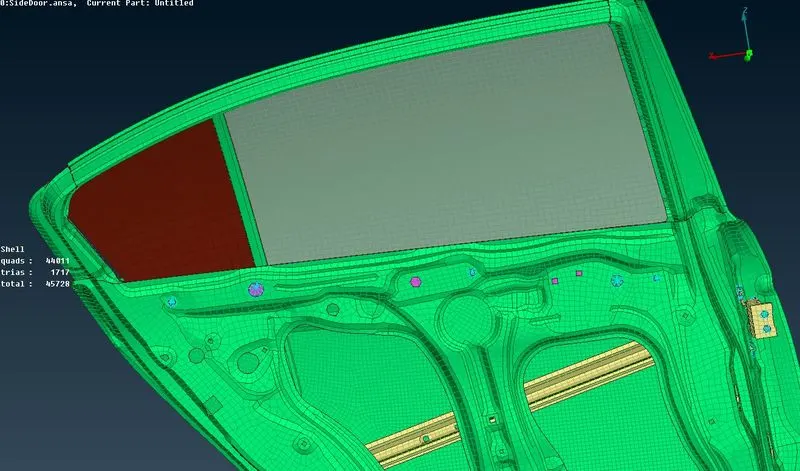
2. Deploying connections at door handle.
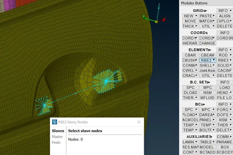
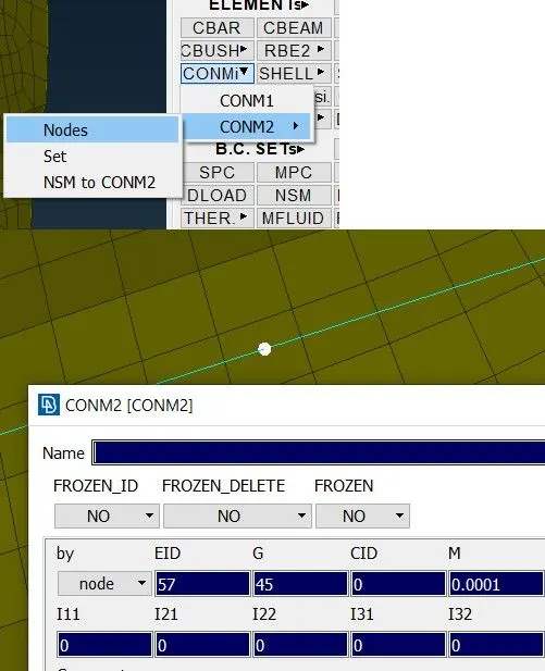
We begin with applying RBE2 many nodes to the door handle at both side to form a RBE2 cluster. Now once the connection is realized we assined RBE2 two nodes to both master nodes of the cluster. Now, under Element panel we assigned 100g of mass to the handle 1e-4tonns.
3. Deploying a Connection between the rail & side glass.
Now, we need to deploy a coonection between the rail as well as side glass. The rail is responsible movement of the glass in upside-down. Here, the rail is extended & RBE2 cooection is assigned between them to visualize rigid support in them. The Rail connection is itself attached to other part of door panel through spot weld as well. 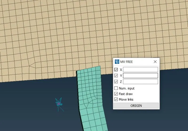
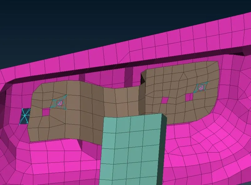
Now the member which holds the rail is attached through spot weld which can be seen below as well. Here, the 3d points were created into spotweld, later RBE Hexa element were chosen to realize the connections. Then to realize this connection, the connection manager is opened from assembly manager. And the converted spot weld point is selected. And some parameters are specified as show. And the FE reresentation of a spot weld connection in NASTRAN deck is RBE3-HEXA-RBE3.
4. Deploying the connections at the side glass region.
The glass is always in closed position for any NVH system. We begin with creating the curve of the window. The glass is selected and curved is formed. Later, these are converted in spotlines which ultimately are converted into CBUSH connections. These are called as weather strips. They are soft material which reduces any chances for glass for demage. They have their own stiffnes values, which also differs from manufacture to manufacture. The curve created at the bottom should be copied using Transform and moved to a certain distance such of10mm. 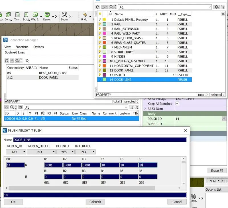
We assigned stiffness values as well.
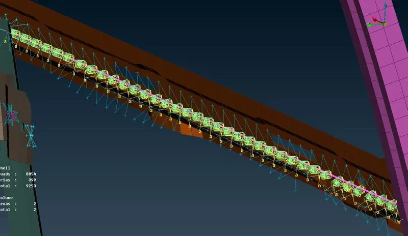
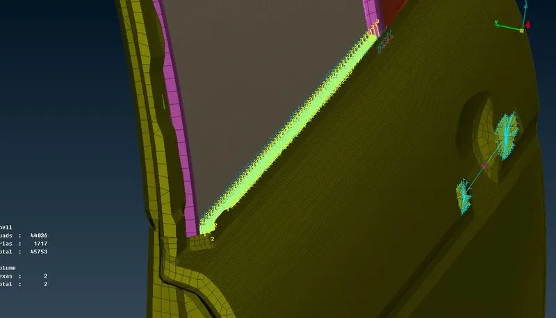
The same CBUSH connection is created for rear quater mirror as well.
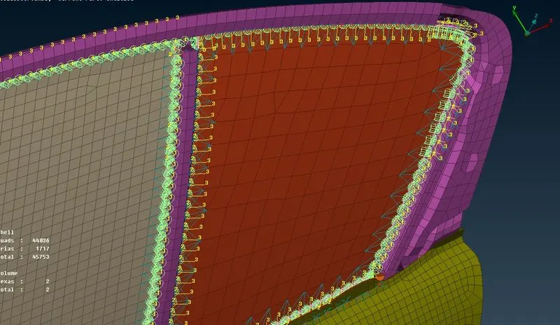
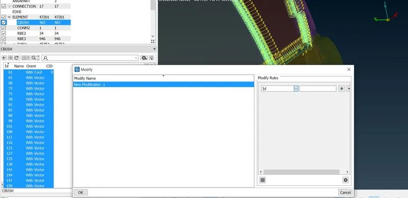
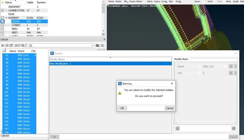
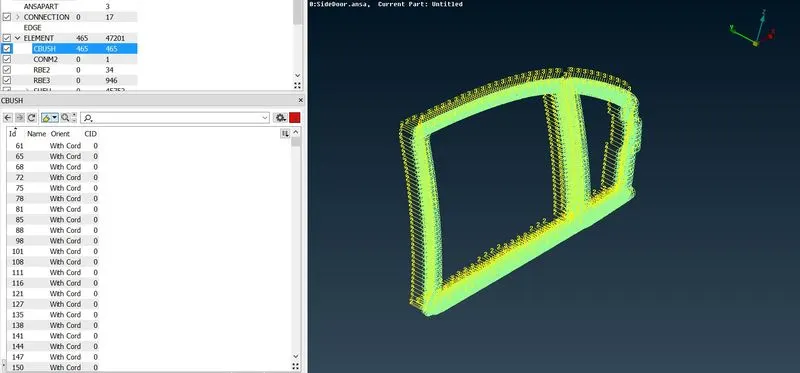
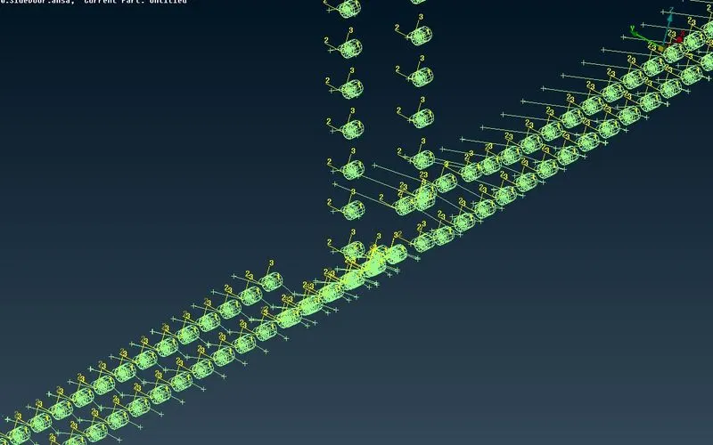
Now, here all the vectors for the formed connections are facing in different directions. We need to assign them in local co-ordinate we done these by assigning the co-ordinate as a local vector for lll connections,
Finally,
CONCLUSION: In this way we have sucessfully assigned connections to door panel.
MODEL: https://drive.google.com/drive/folders/1FkS5kSDGhCpMetTvNvDSTHLc1ltPsxqb?usp=sharing