Conjugate Heat Transfer Analysis on a graphics card.
Aim :- Thermal(conjugate heat tranfer) analysis on a graphic card.
Theory :-
Thermal analysis is an important part of the design process, especially if modern, ultra-fast components are used. For example, FPGAs or fast A/D converters may easily dissipate several watts of power. Because of this, PC boards, enclosures and systems must be designed to minimize the impact heat will have on their proper functioning. Sometimes it becomes a considerable constraint on the developer’s creativity. For example, an air-cooled design on a 3U Compact PCI Express card may be limited to only 20W before some serious thermal problems start to develop on the board due to insufficient airflow between boards and between parts on the board. Complex designs aren’t the only boards and systems that need to be checked for thermal violations. A simple handheld gadget – a cell phone or a music player may also overheat under certain conditions. Many people are familiar with notebook computers that become uncomfortably hot. Such temperatures may cause injury to the user, and they also can contribute to accelerated aging of the battery, possibly even causing a fire.
If you are developing a board that will be only made in small quantity and used in your own lab for a single purpose it still makes sense to verify that the board will work. As an example, we saw a microwave board that was carefully laid out and validated in an EM simulator. It actually performed very well, RF-wise. However the designer, focusing exclusively on microwave components, neglected to calculate the power that is dissipated by the many regulators that the board had. Those regulators were not given enough copper to dump the heat into. As result, while the board was great in RF terms, within minutes it heated up almost to the ignition point — it couldn’t be touched, and it couldn’t be allowed to run because the regulators would burn out and the unregulated power would likely damage everything else. That board, without rework, could not be used even in a lab environment; it was nothing short of a fire hazard. A couple of formulas and a quick simulation could have prevented such a problem.
We can use specialized CAD software that allows a designer to enter a 3D model of the entire device — that includes the board with components, fans (if present), and the enclosure with ventilation openings. Then heat sources are added into simulated components — typically into models of ICs that produce enough heat to be concerned. Ambient conditions are specified, such as air temperature, vector of gravity (for convection calculations) and sometimes external radiation load (such as solar.) Then the model is simulated; results usually include temperature and airflow plots. Within enclosures it is also important to get pressure plots.
Purpose behind performing conjugate heat tranfer simulation of graphic card :-
- Thermal simulation helped in identifying the high temperature zone that could potentially damage the electronic components on the graphics card
- Suggested the changes in the cooling fins layout to improve the efficiency of the heat dissipation
- Thermal simulation helped to reduce the cost of the testing and prototyping
Pre-processing steps :-
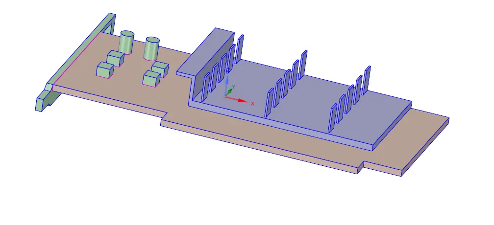
Imported CAD geometry in Space-claim :-
Mesh generation of CAD model in Design-modeler :-
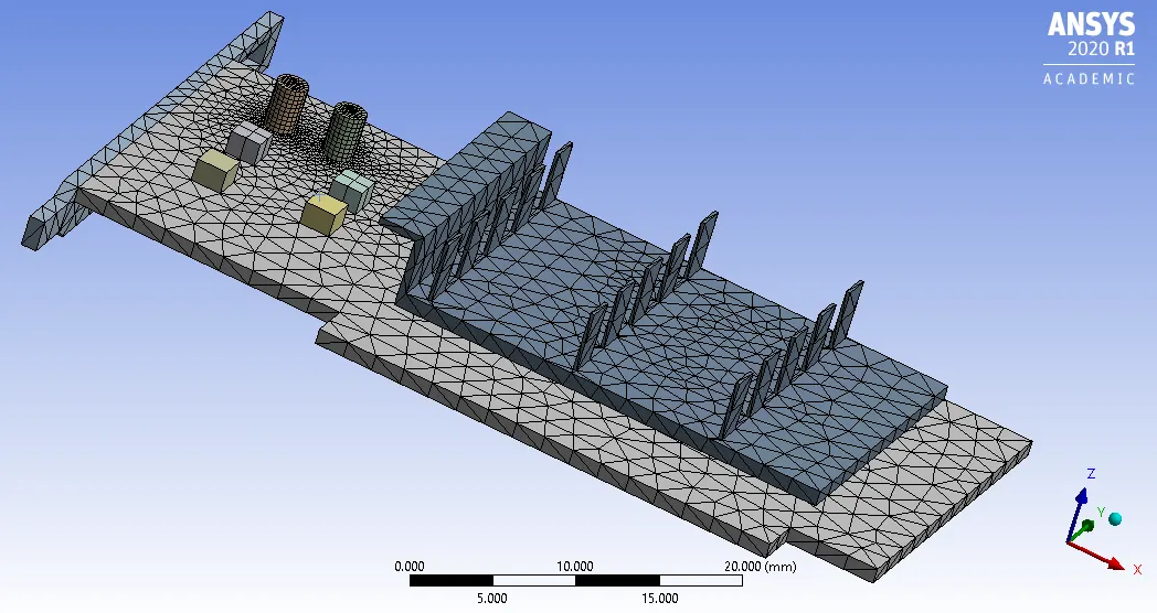
Mesh Settings :-
1. For Base Mesh 2. For Refine mesh
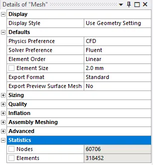
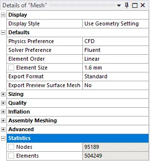
Note:- Here the mesh setting have been adjusted at 2mm and 1.6mm for base grid and refine grid repectively. The reason behind provision of 1.6mm mesh size to refine grid is that We don't have much cells due to academic license issue, Hence We are limited to this cells.
Boundary Conditions and other settings :-
Inlet condition for enclosure
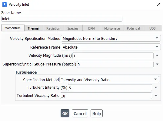
Outlet condition for enclosure
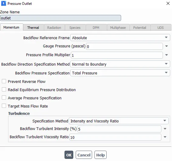
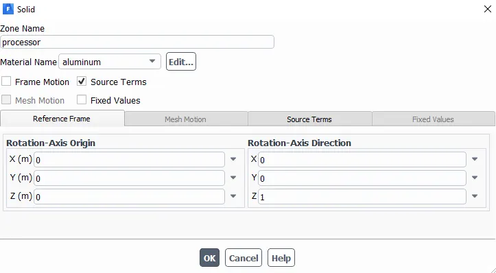
Wall Condition for processor :-
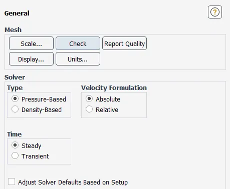
Solver based setting :-
Turbulence Model :-
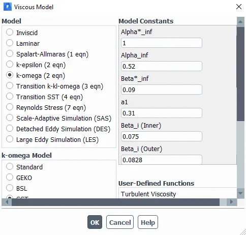
Note :- Here air has been taken as fluid material for enclosure whereas aluminium has been taken as solid material for graphic card.
Post-processed Results :-
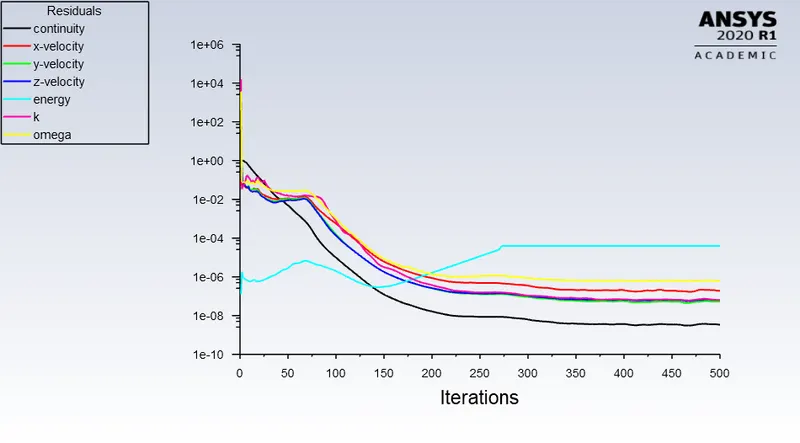
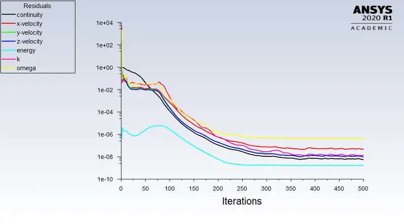
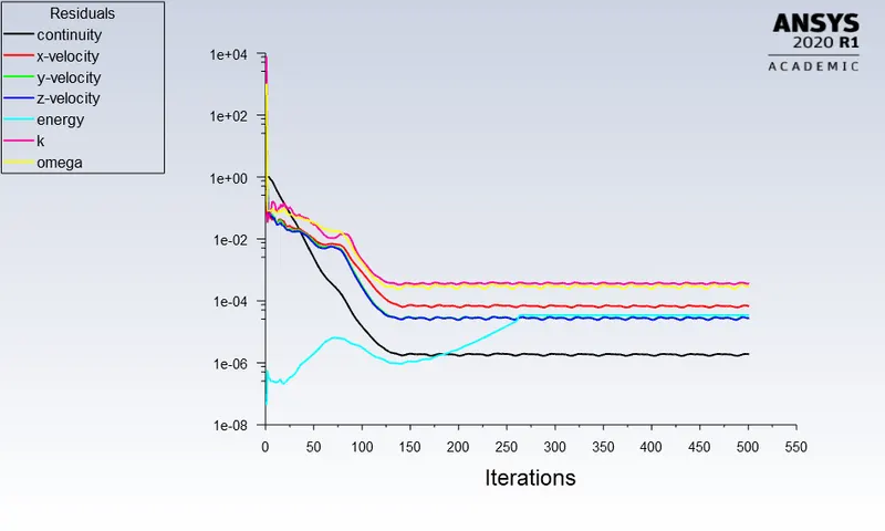
Residual plot:-
At velocity of 1 m/s
For Base mesh
For Refine mesh
At velocity of 3 m/s
For Base mesh
For Refine mesh
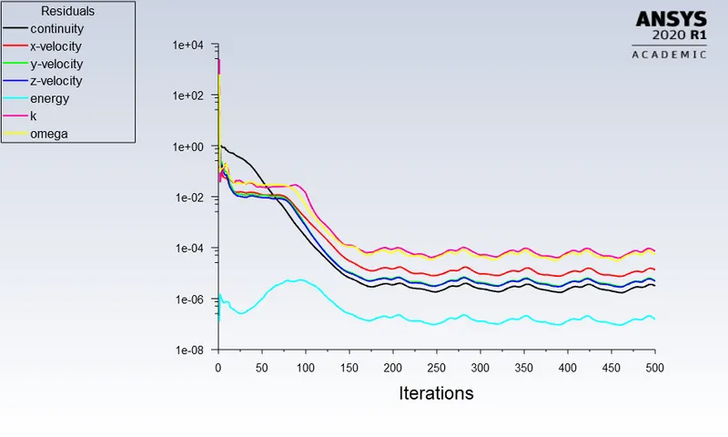
At velocity of 5 m/s
For Base mesh
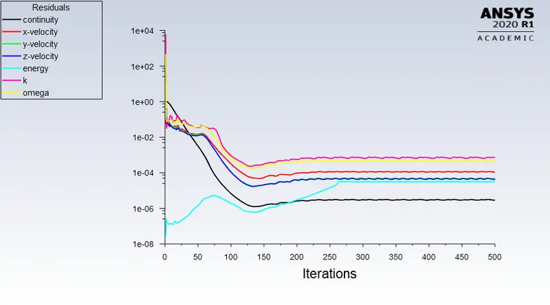
For Refine mesh
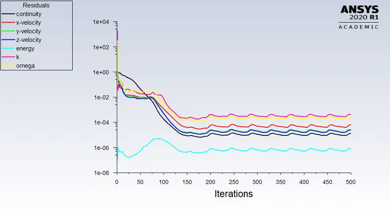
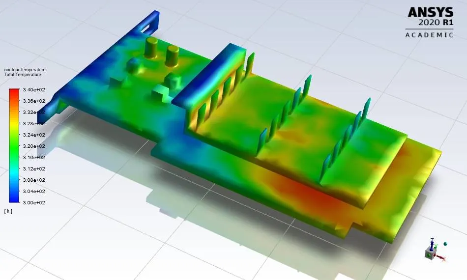
Temperature contour at velocity of 1 m/s
For Base mesh
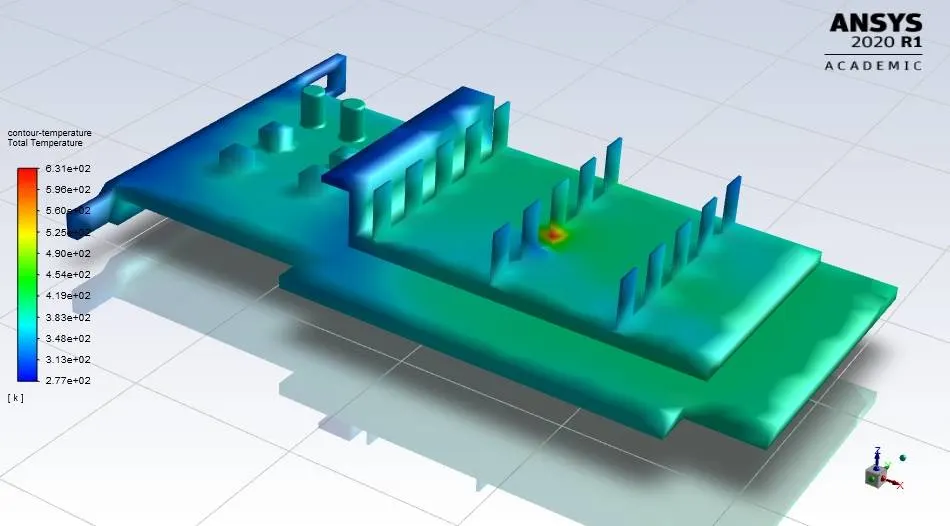
For Refine mesh
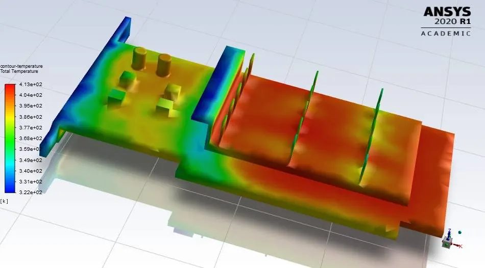
Temperature contour at velocity of 3 m/s
For Base mesh
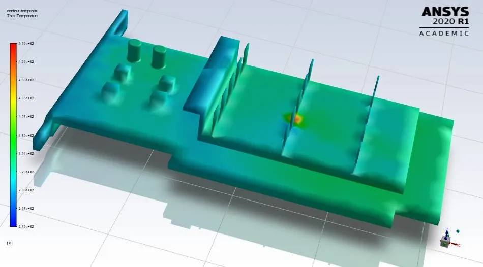
For Refine mesh
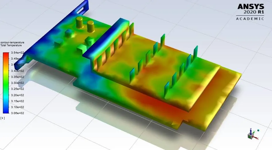
Temperature contour at velocity of 5 m/s
For Base mesh
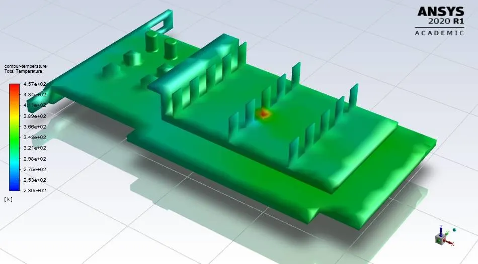
For Refine mesh
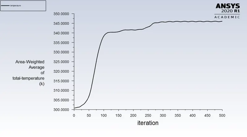
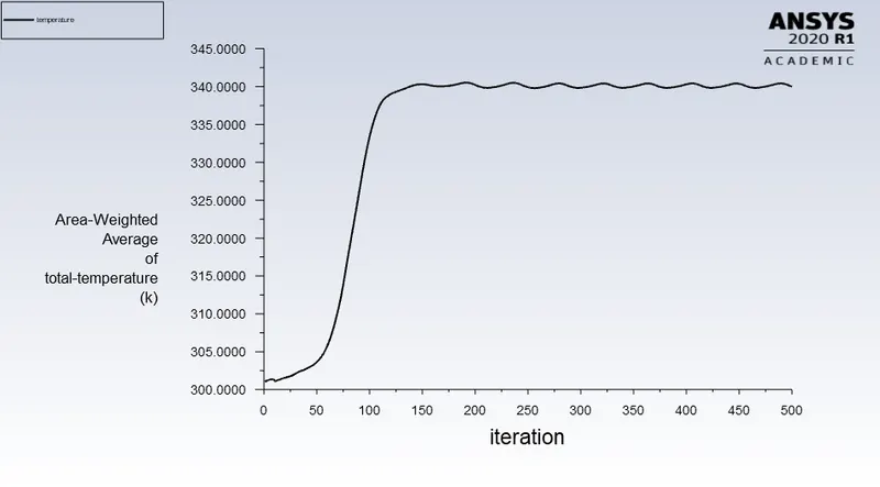
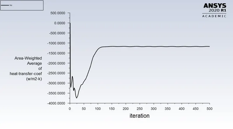
Maximum temperature and Heat transfer coefficient :-
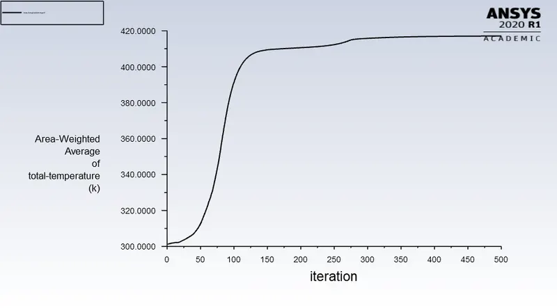
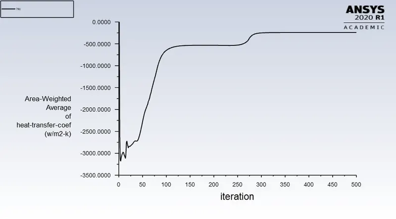
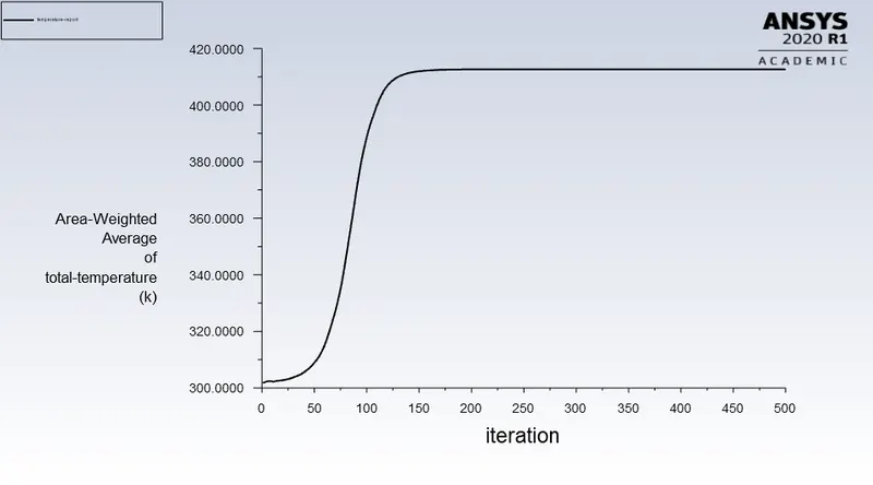
At velocity 1m/s :-
For Base mesh
For Refine mesh
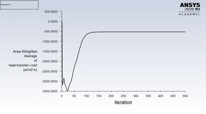
At velocity 3 m/s
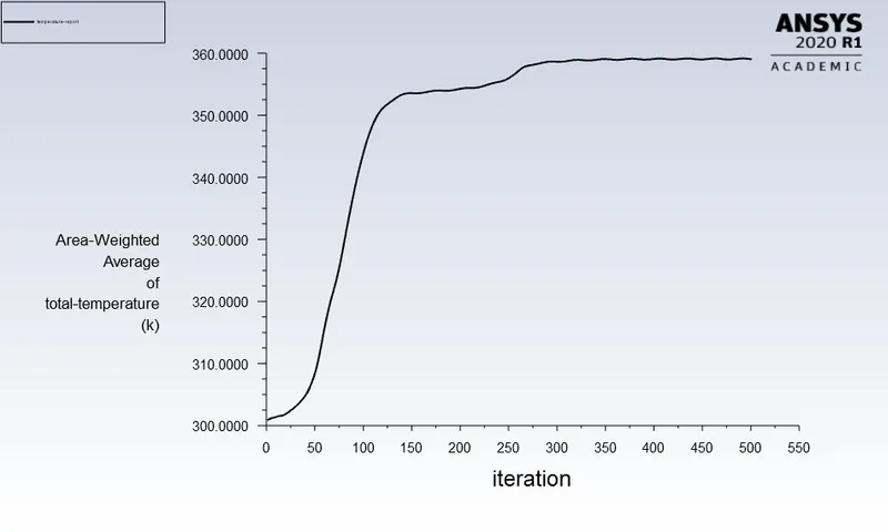
For Base mesh
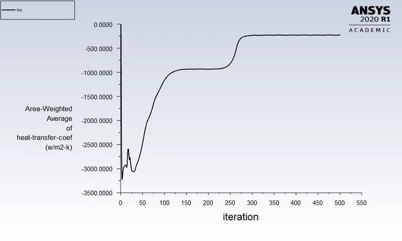
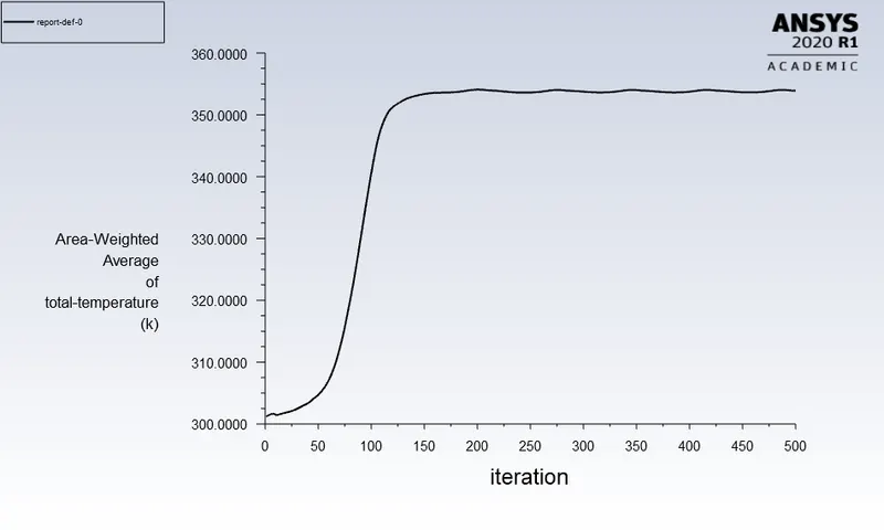
For Refine mesh
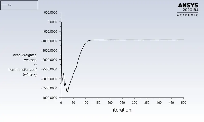
At velocity 5m/s :-
For base mesh
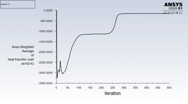
For Refine mesh
Observation :-
Effect of mesh on the result :-
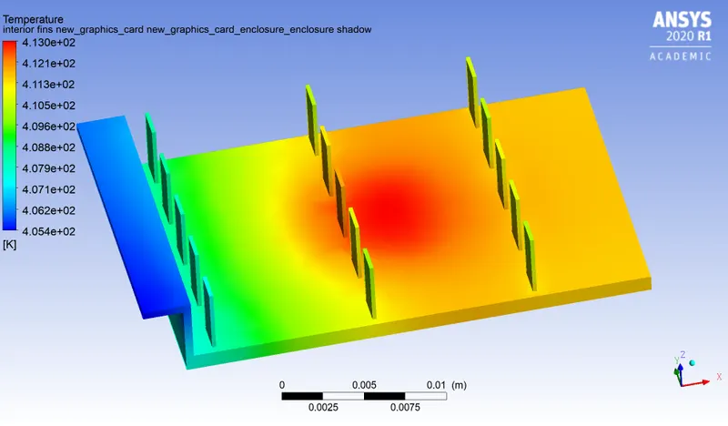
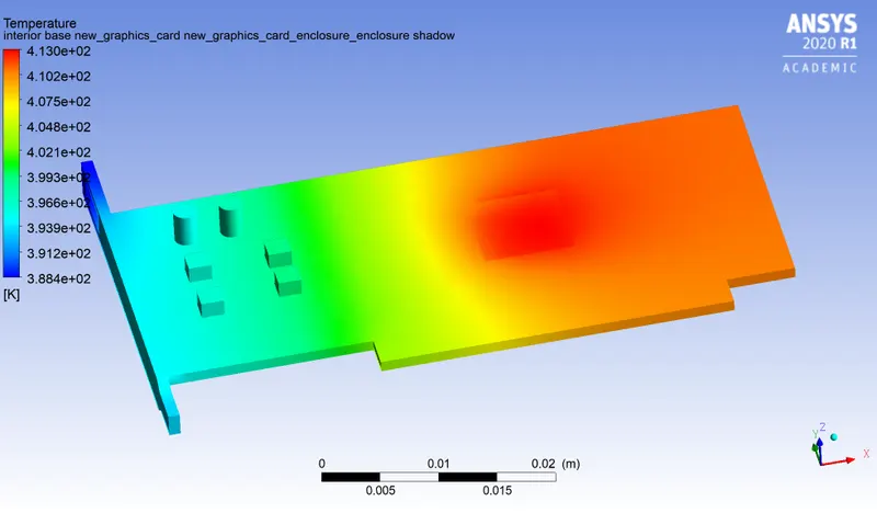
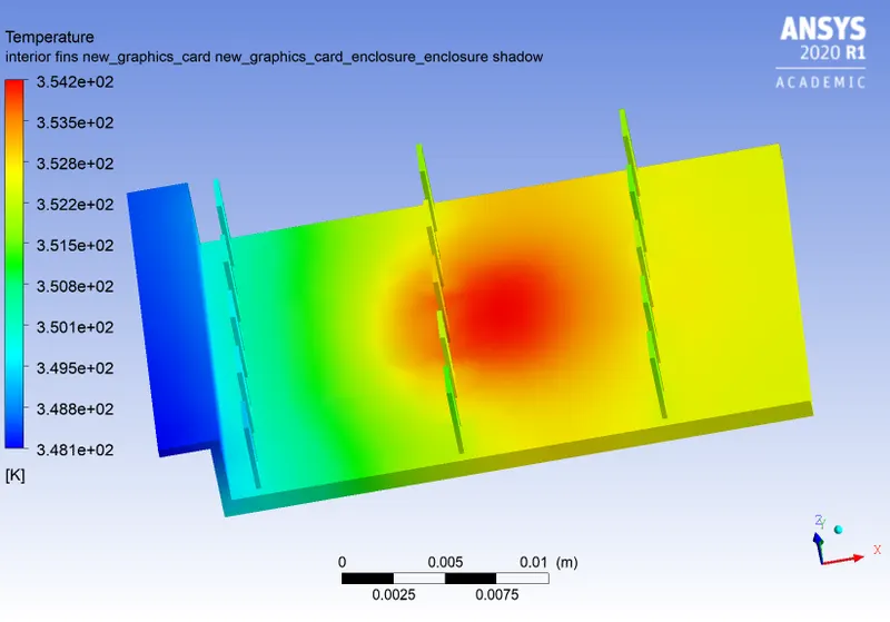
For base mesh, We were not able to see Temperature distribution in the temperature contour of Graphic card whereas when decrease the mesh size, We saw that there was huge temperature distribution in contour. This reveal that We should have atleast proper refine mesh which can show a proper distribution in the plot.
Effect of velocity on result :-
When velocity of air was increased, We saw that temperature across graphic card was decreased which gave us information that increase in velocity would result in decrease in temperature.
Effect of Mesh size on Convergence :-
Here We observed that When We used both base mesh and refine mesh, We found that convergence was relatively much below the the tolerance level in case of refine mesh which proves that level of convergence increases more with refine mesh. Apart from it, We too observed that result for temperature and heat transfer coefficient plot was much stable in case of refine mesh. Hence, It provides us evident that We have reached to the convergence point.
Maximum temperature and heat transfer coefficient obtained on processor was as follow:-

Potential hotspot on graphic card are :-
For velocity of 1 m/s
At the fins of graphic card
At base of graphic card
For velocity of 3 m/s
At the fins of graphic card
At the base of Graphic card
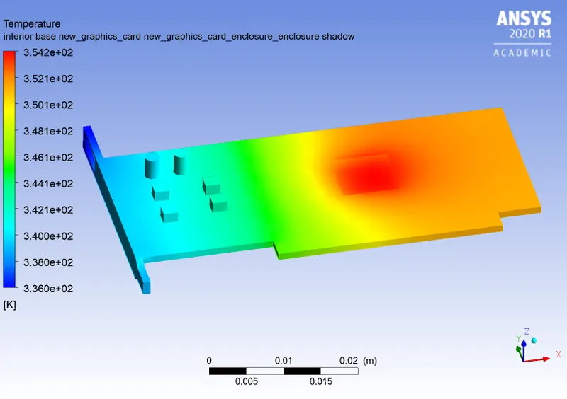
For velocity of 5 m/s
At the fins of graphic card
At the base of graphic card