Conjugate Heat Transfer Analysis on a graphics card.
AIM:-
- To perform a steady-state conjugate heat transfer analysis on a model of a graphics card.
- To run the simulation for best possible mesh with combination of coarse and refined mesh in different regions and explain the mesh settings.
- run the simulation by varying the velocity from 1m/sec to 5m/sec for at least 3 velocities and discuss the results.
- To find out the maximum temperature and heat transfer coefficient attained by the processor.
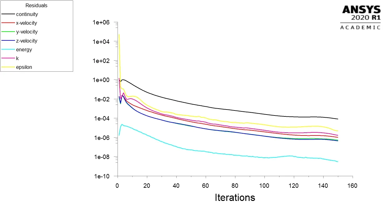
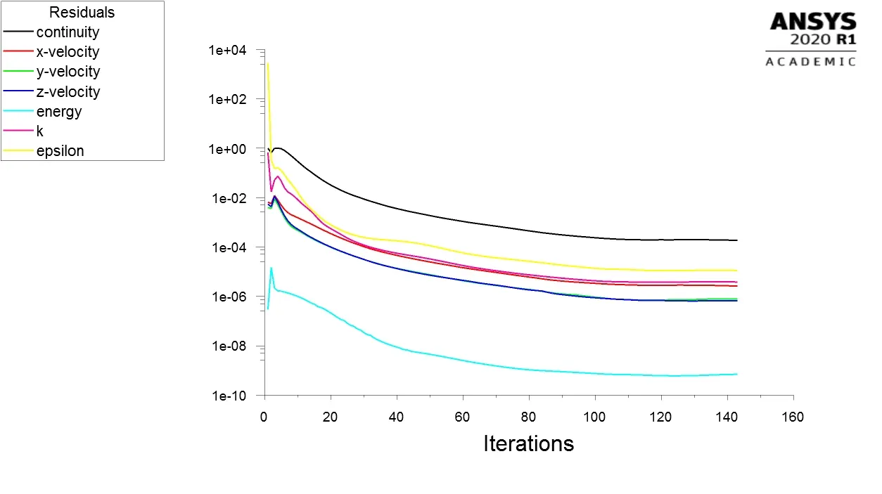
- To prove that the simulation has achieved convergence with appropriate images and plots.
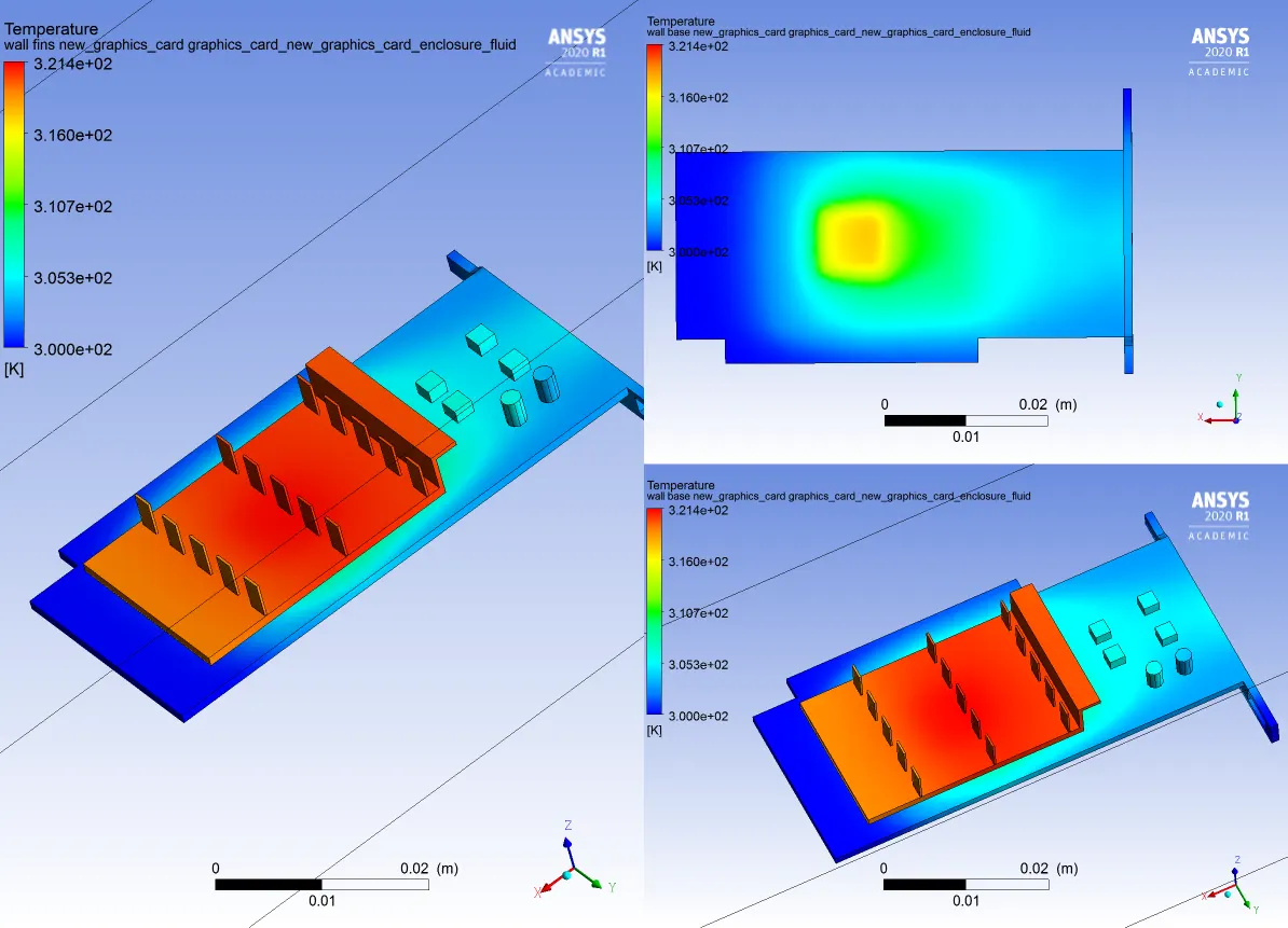
- To identify potential hotspots on the model.
EXPLANATION AND SIMULATION:-
Geomertry:-
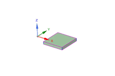
I have used the given geometry and 'shared' them So that the information can be passed through the geometry in space claim.
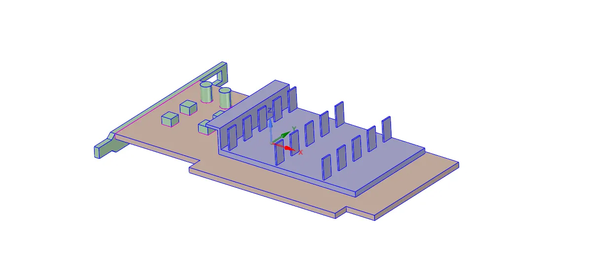
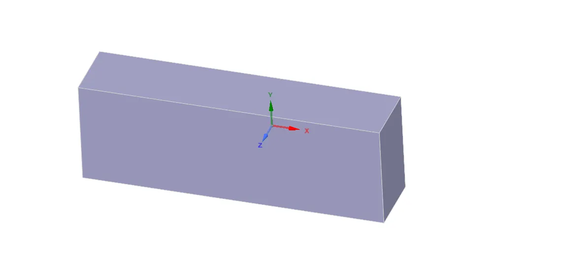
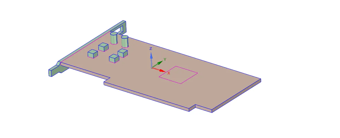
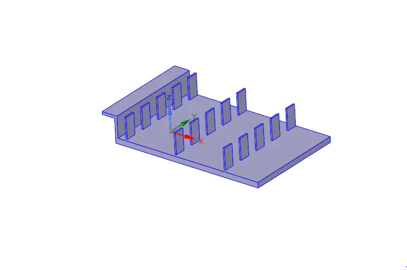
Enclosure Base Fins Processor
Mesh:-
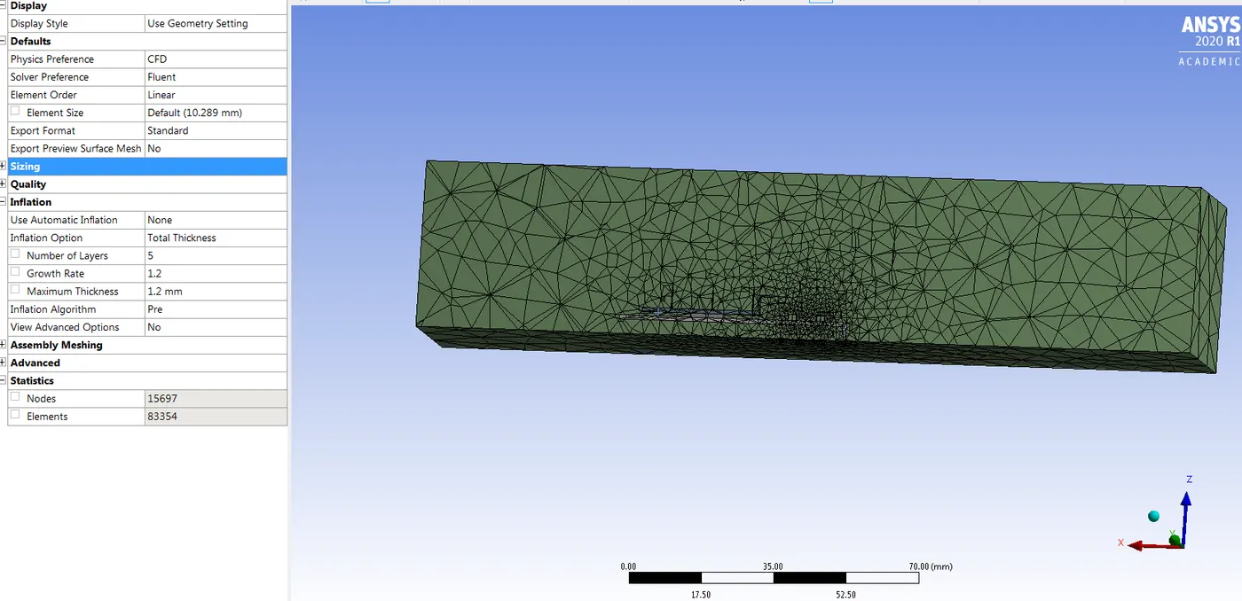
In this simulation I am using two different types of meshes.
Named sections:-
Inlet
Outlet
Wall - bottom side
Symmetry - other sides
Fin
Processor
Base
1. Baseline mesh with element size:-10.289mm
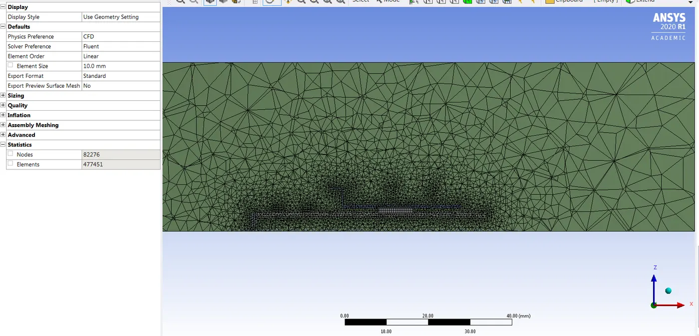
2. Refined mesh with element sizes and body sizing :-
Enclosure Mesh element size:- 5mm
Body sizing for Fins element size :- 0.3mm
Body sizing for Processor element size :- 0.1mm
Body sizing for Base element size :- 0.2mm, Capture curvature is on here.
As the heat is generated from the processor. The main and closely effected bodies are close to the processor. The base and fins are the closest to the processor where heat exchange is going to happen by conduction and convection. So the enclosure is refined a bit as we have a restriction of 500000 cells restriction. This is the best possible mesh we can use to get the required results.
Case setup in Fluent:-
I have used steady state, pressure based and absolute velocity.
Energy equation is turned on as we are dealing with temperature here.
Viscous model is K-epsilon model.
Now let's create materials for the graphic card
For Enclosure the Air as fluid
Density:- 1.225 Kg/m^3
Heat capqacity:- 950 J/kgk
Thermal capacity:- 0.29 W/mk
For Fins solid aluminium
Density:- 2719 Kg/m^3
Heat capqacity:- 871 J/kgk
Thermal capacity:- 202.4 W/mk
For Base solid FR4 (glass reinforced epoxy laminate material)
We don't have this materail in the fluent database so I have to creqated this material.
Density:- 1850 Kg/m^3
Heat capqacity:- 950 J/kgk
Thermal capacity:- 0.29 W/mk
For Processor solid silicon
We don't have this materail in the fluent database so I have to creqated this material.
Density:- 2000 Kg/m^3
Heat capqacity:- 710 J/kgk
Thermal capacity:- 150 W/mk
Boundary Conditions:-
Velocity Inlet:- 1m/s, 2.5m/s and 4.8m/s.
Pressure-outlet:-1atm.
Cell-zones:- allot all the zones and apply heat source factor for the processor.
Heat generation rate is 2.4337e7 W/m^3.
A 2GB graphic card is assumed to generate above heat.
I have used hybrid intialization with 150 iterations.
RESULTS:-
CASE:-1
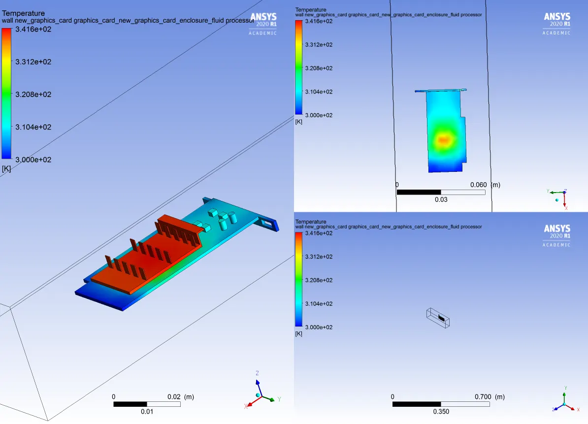
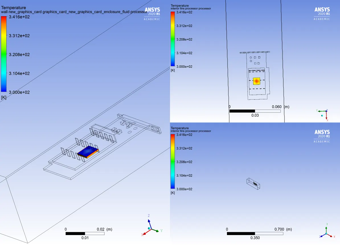
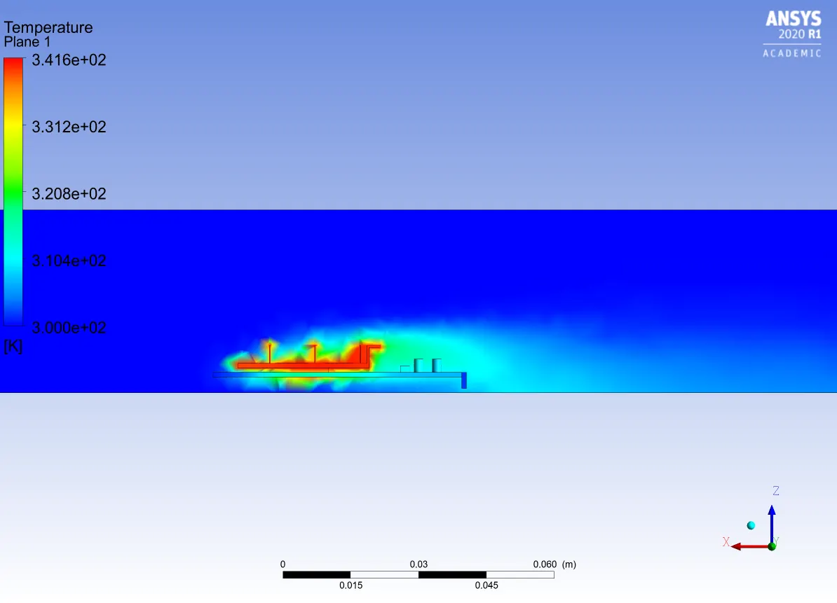
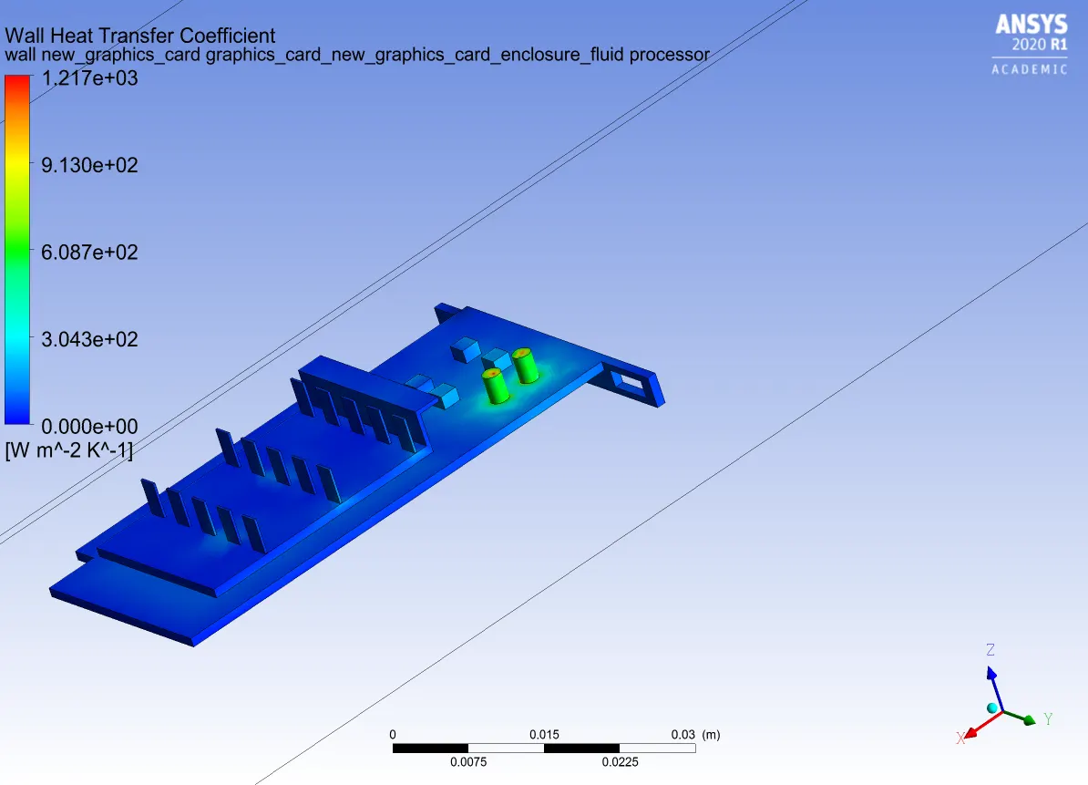
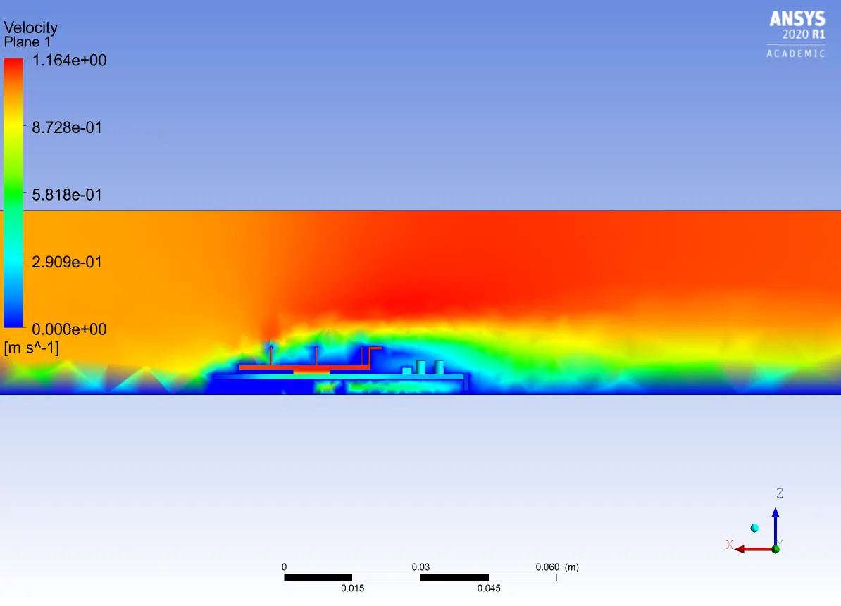
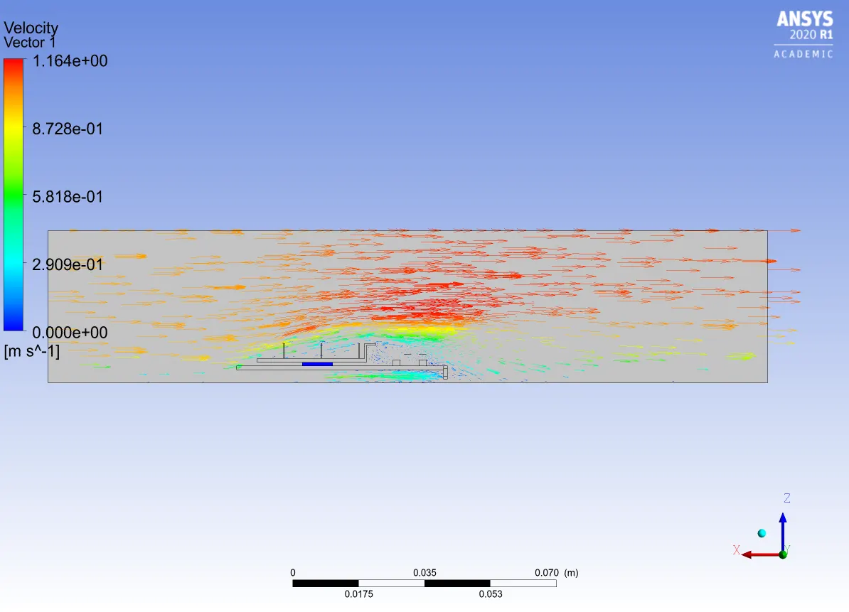
Let's see the Baseline mesh simulation with velocity:-1m/s
Residuals:-
Temeprature contours:-
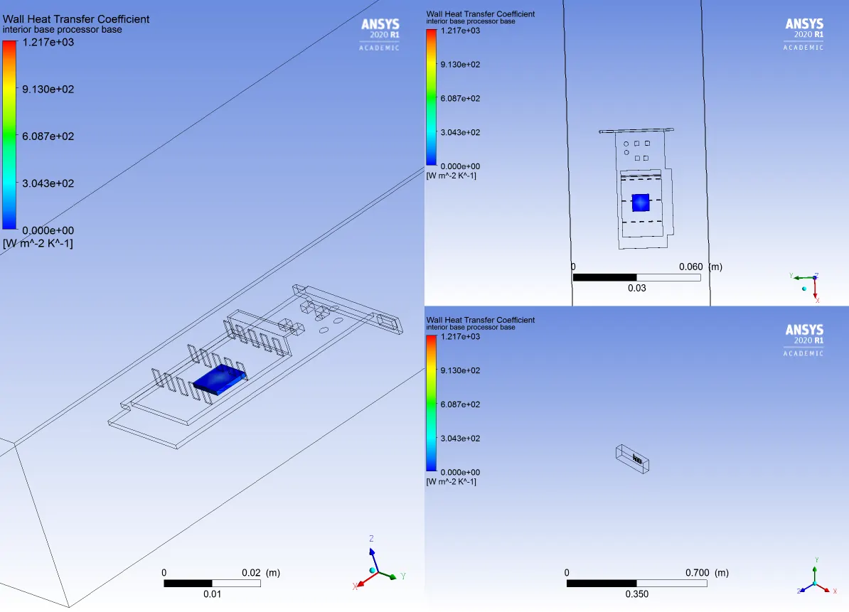
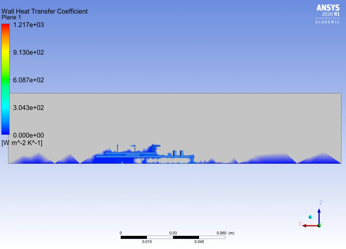
Wall Heat Transfer:-
Velocity:-
CASE 2:-
Nope I am going to simulate refined mesh state with velocity :-1m/s
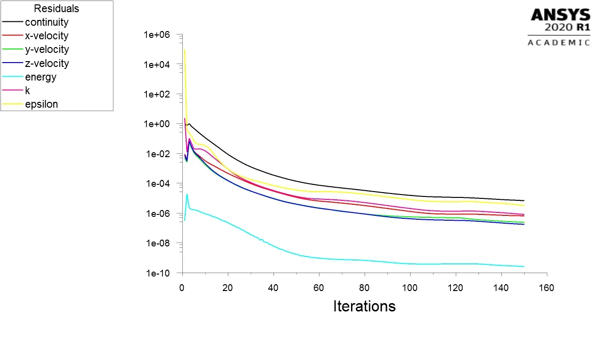
Residuals:-
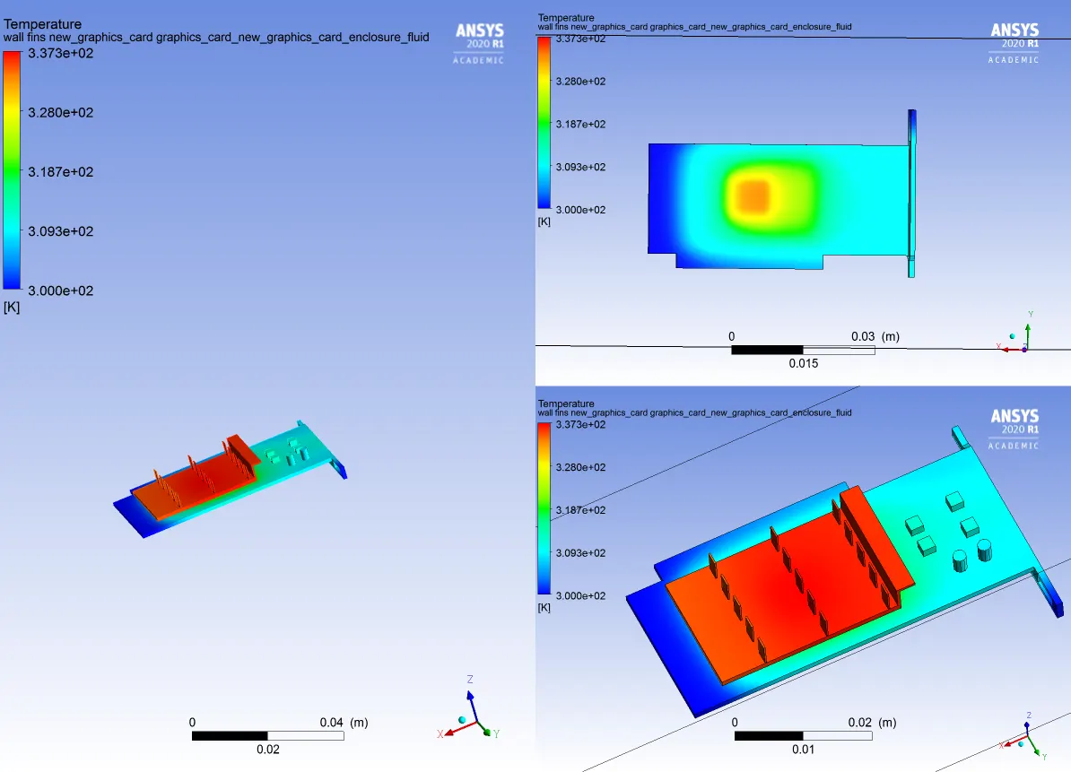
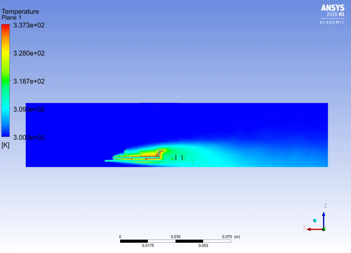
Temperature:-
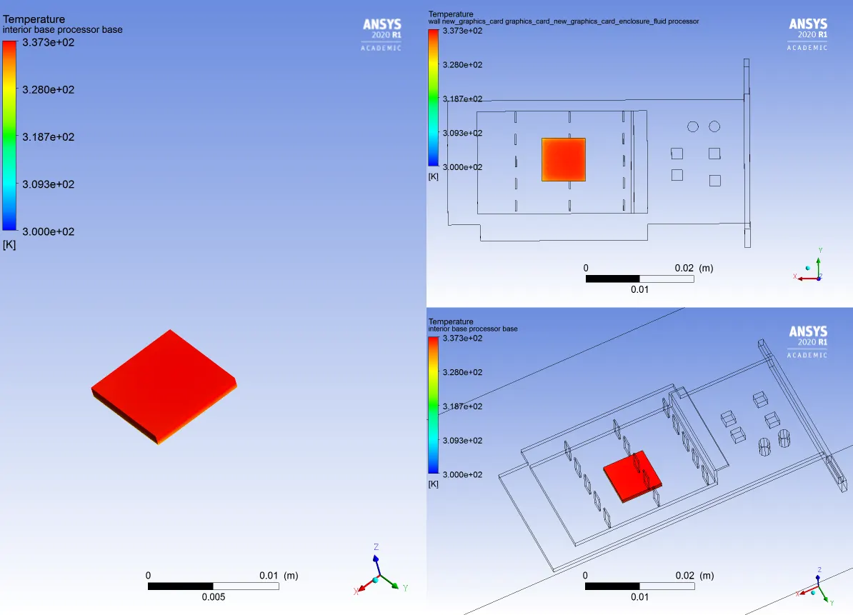
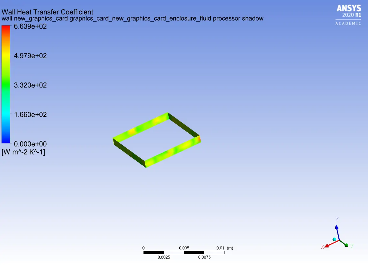
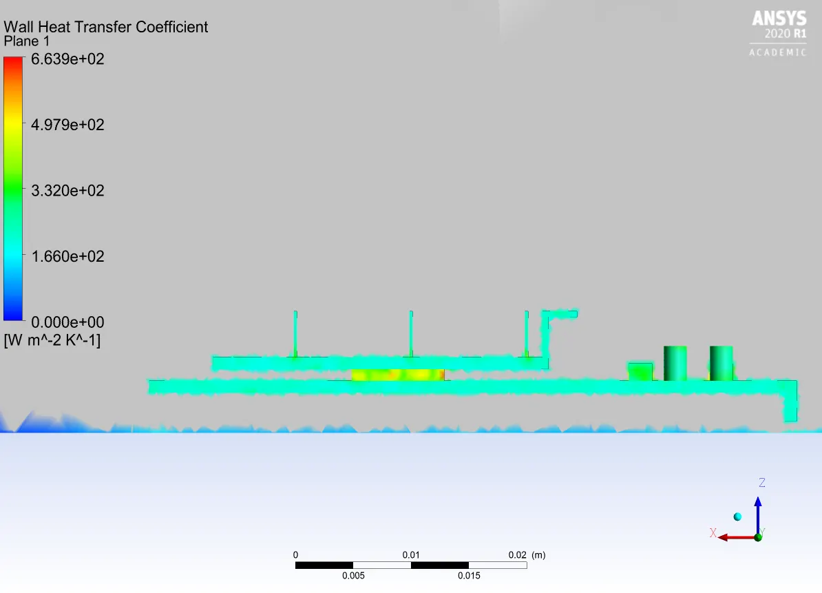
Wall Heat Transfer:-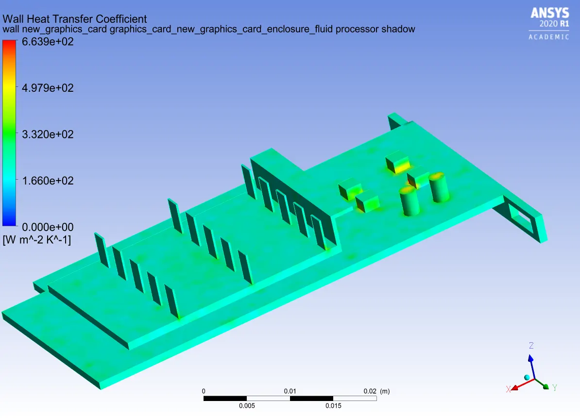
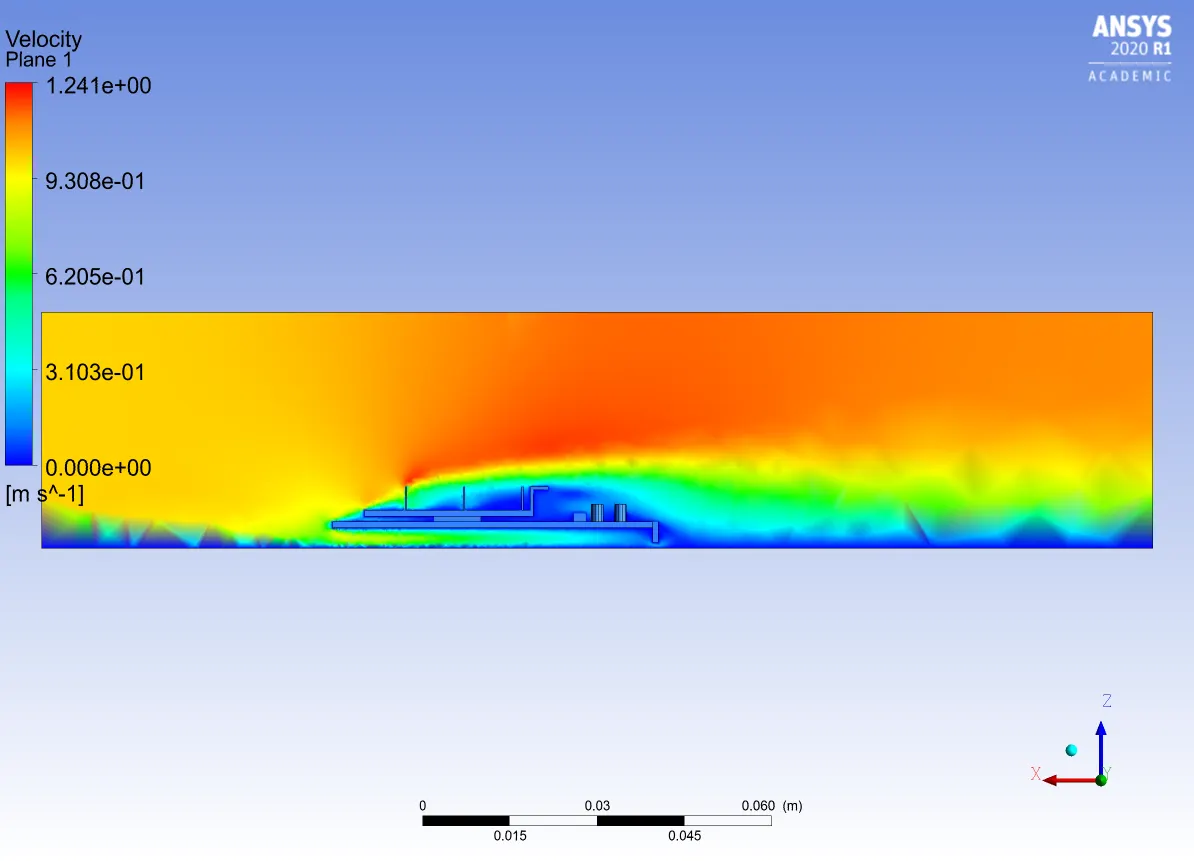
Velocity:-
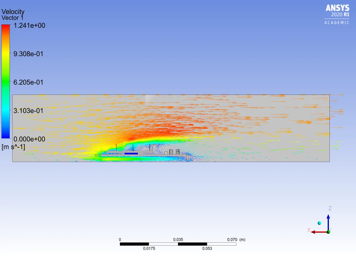
CASE 3:-
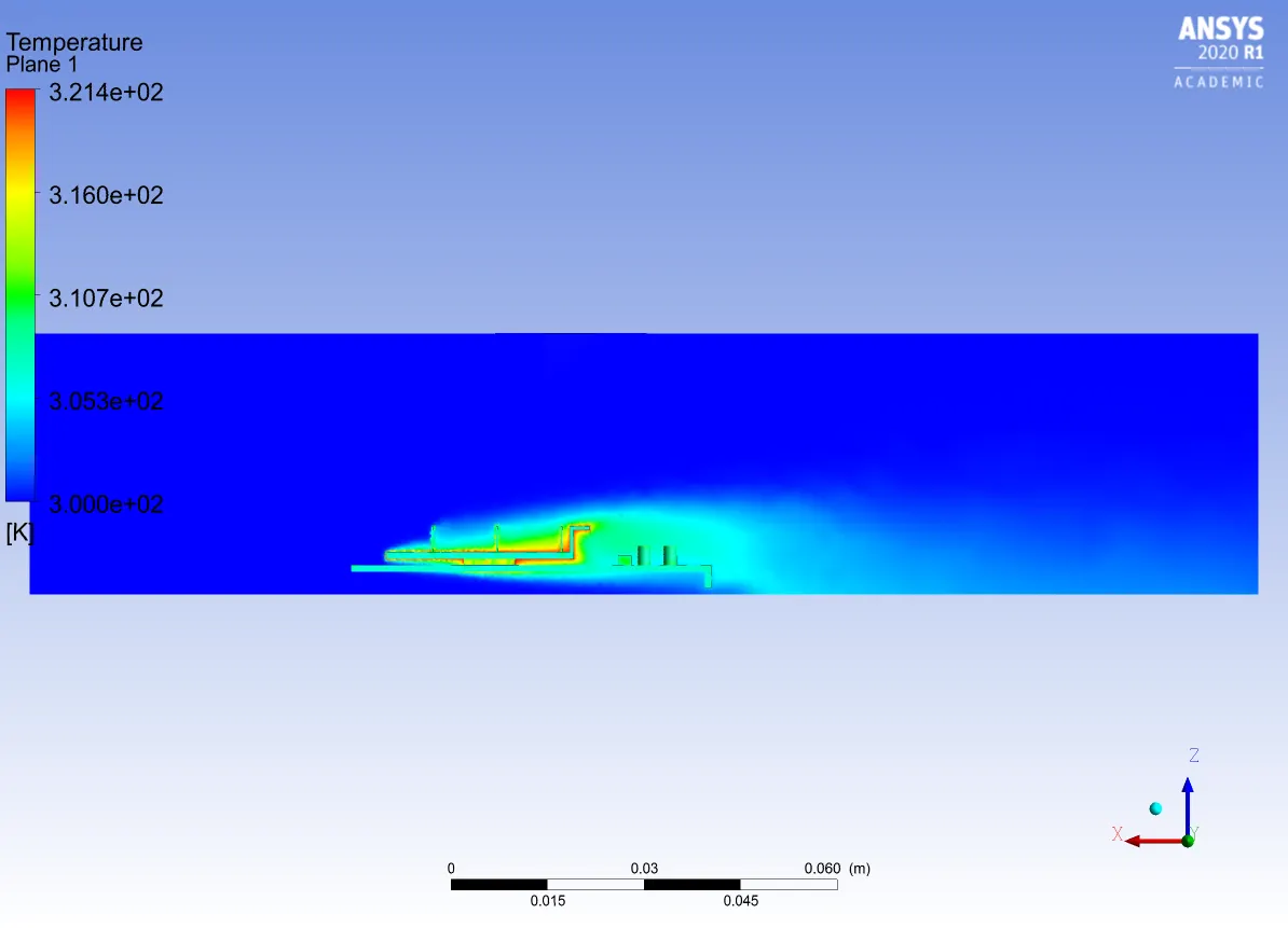
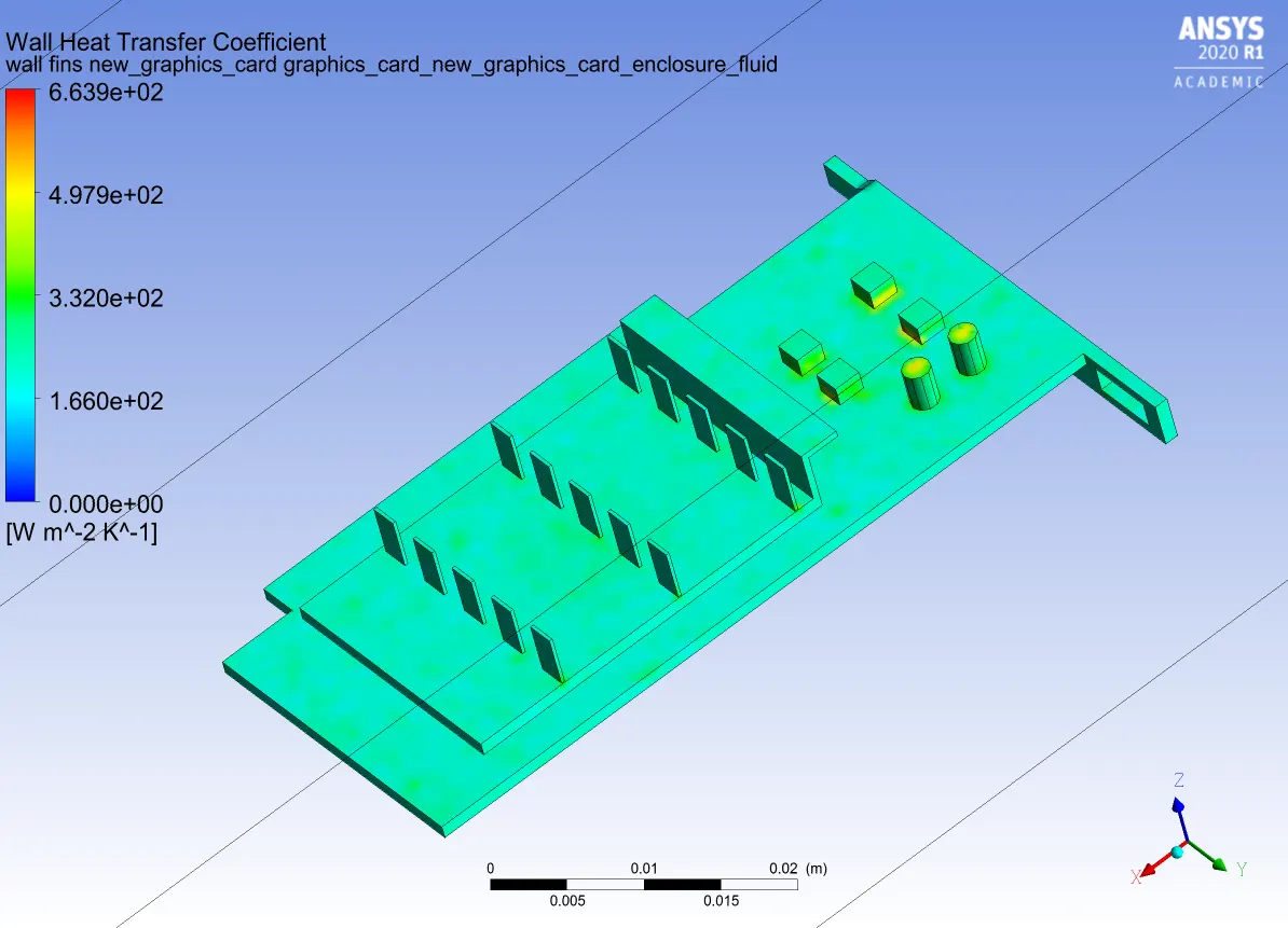
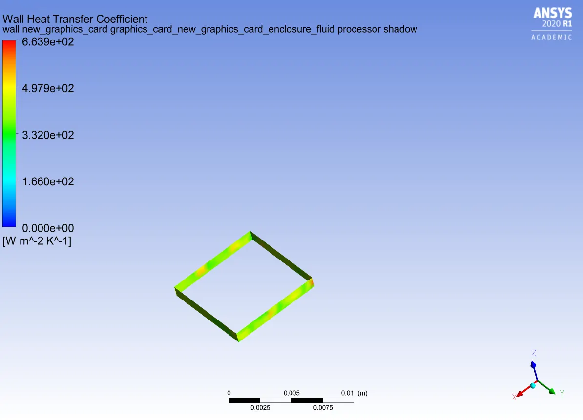
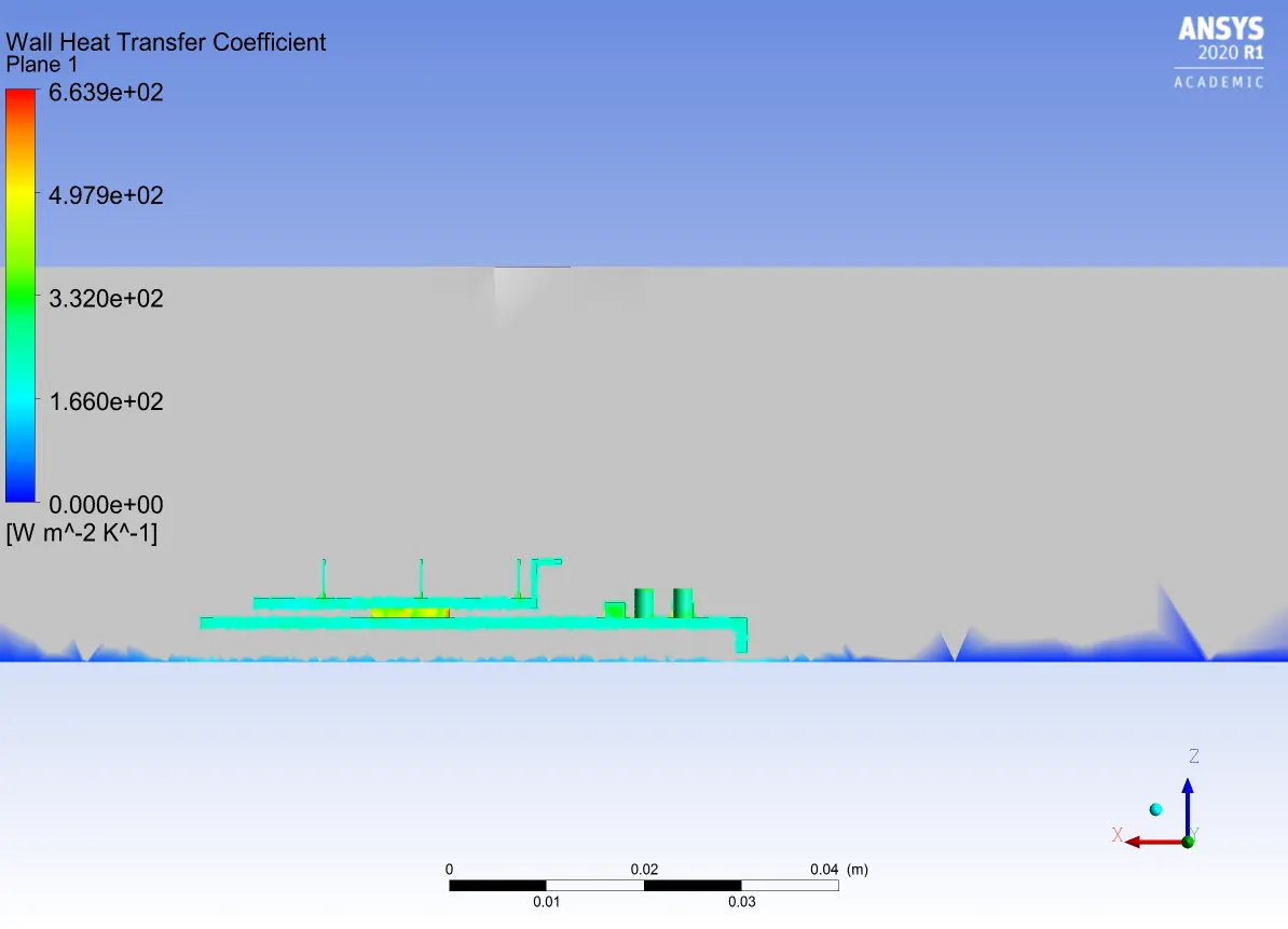
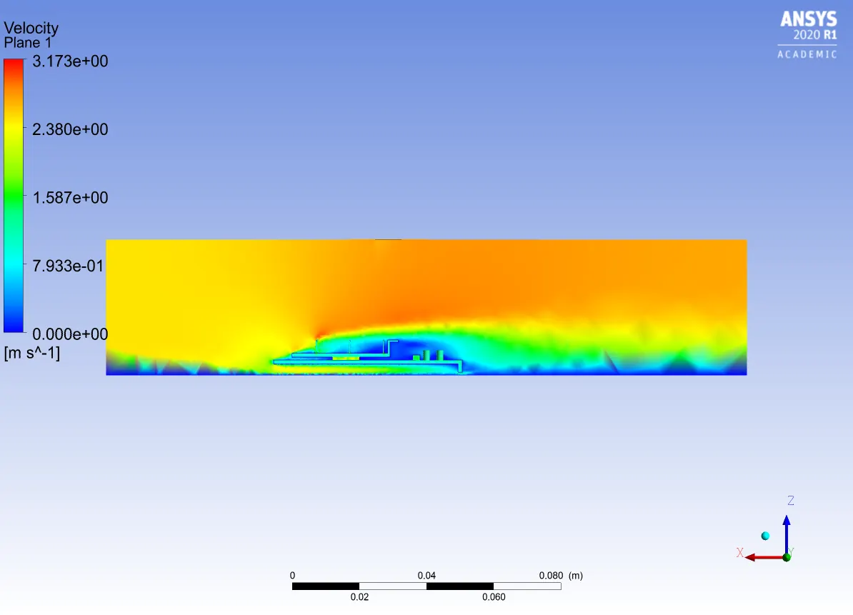
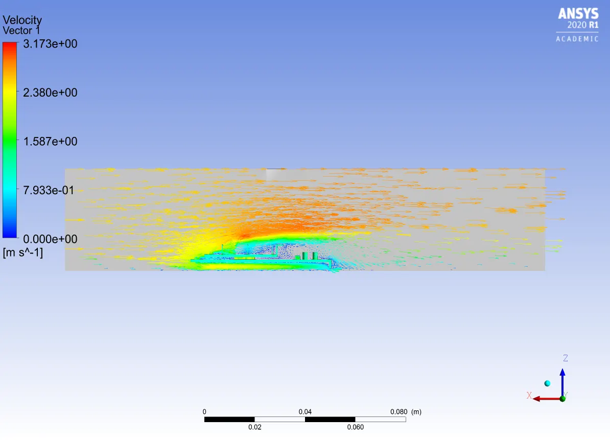
Nope I am going to simulate refined mesh state with velocity :-2.5m/s.
Residuals:-
Temperature:-
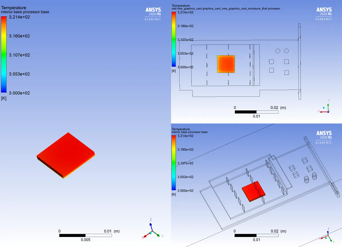
Wall Heat Transfer:-
Velocity:-
CASE 4:-
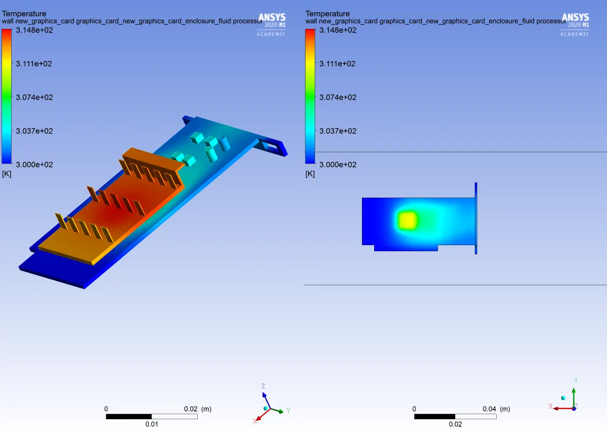
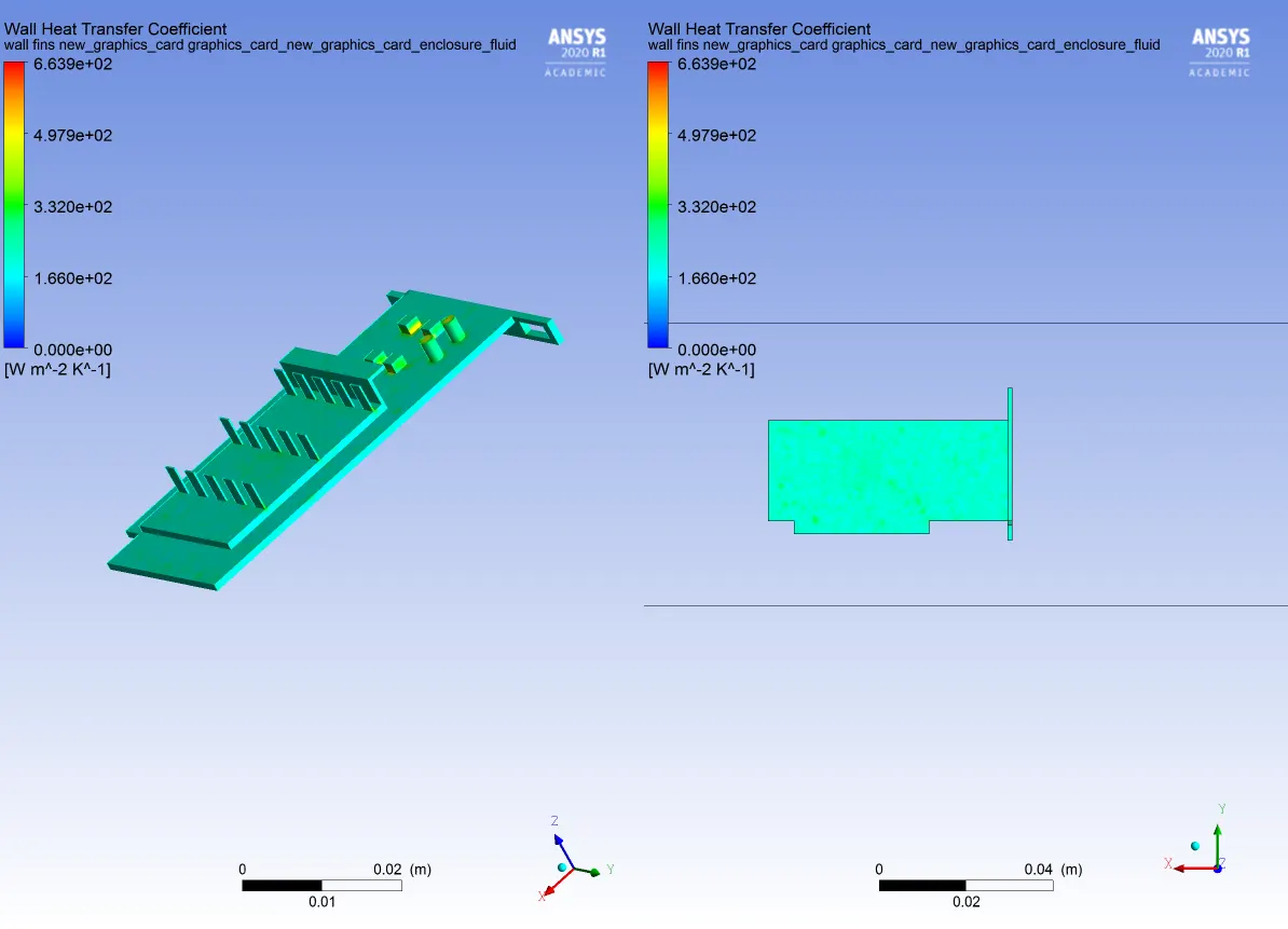
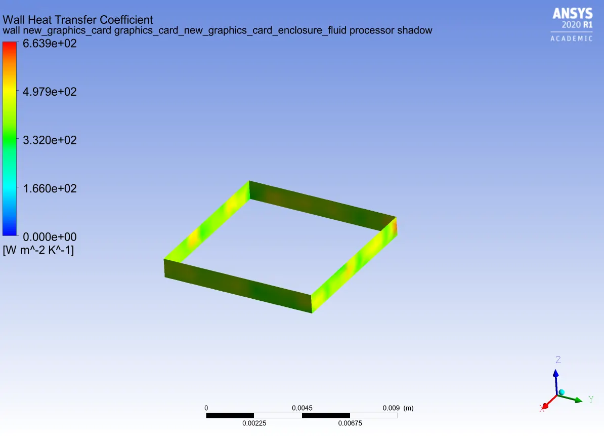
Nope I am going to simulate refined mesh state with velocity :-4.8m/s
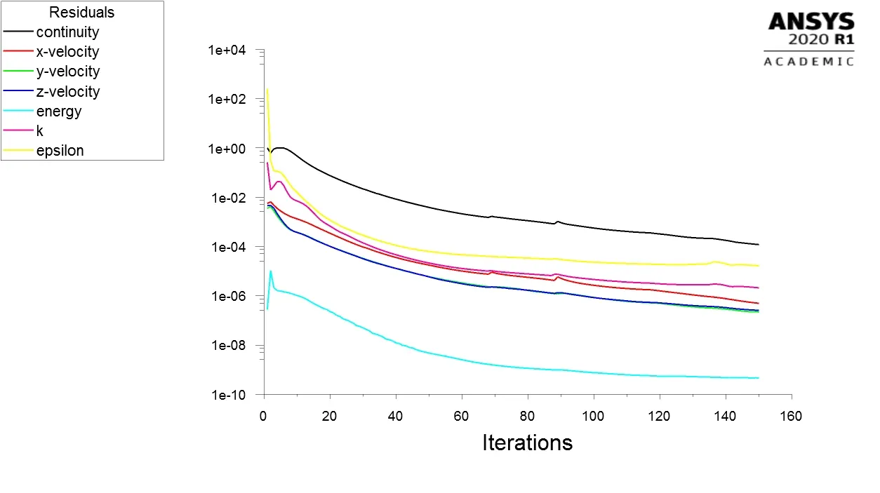
Residuals:-
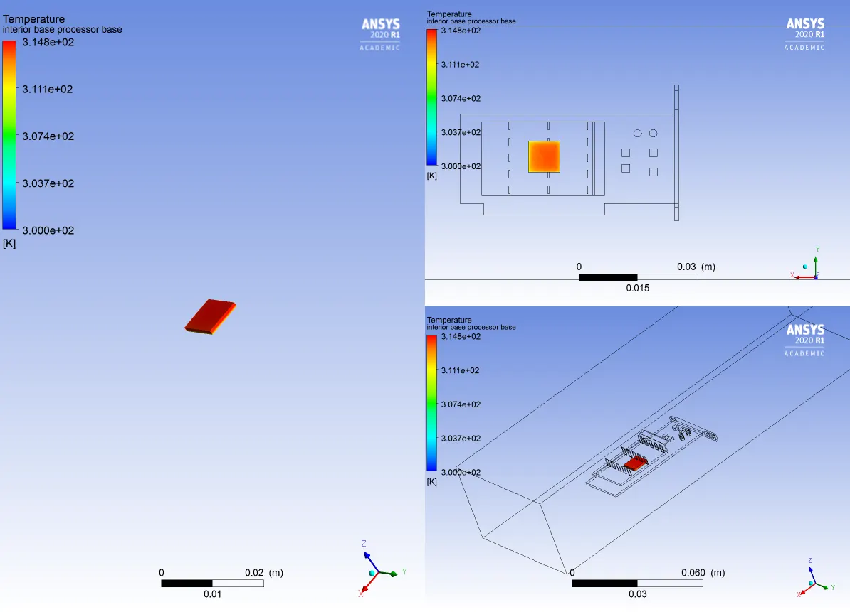
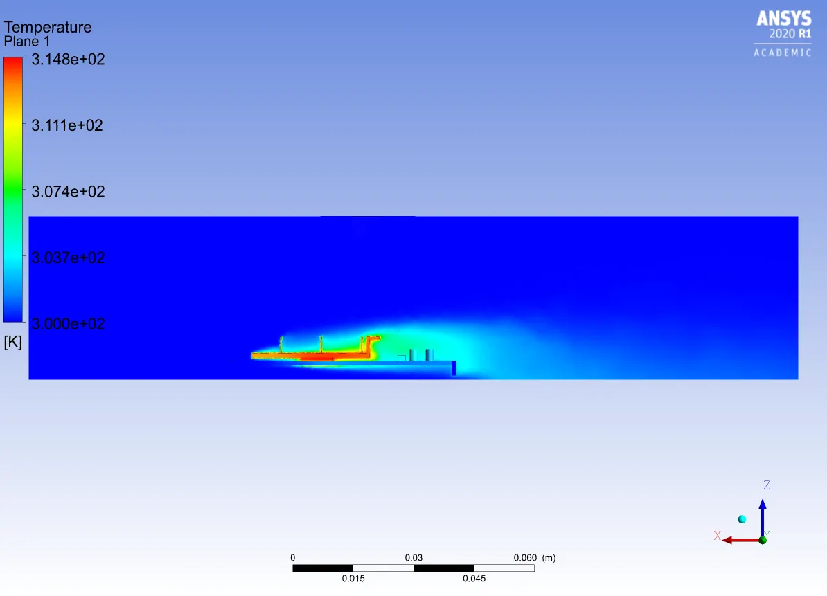
Temperature:-
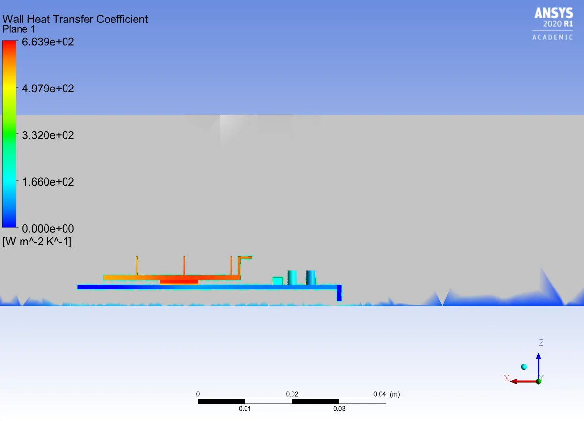
Wall heat Transfe:-
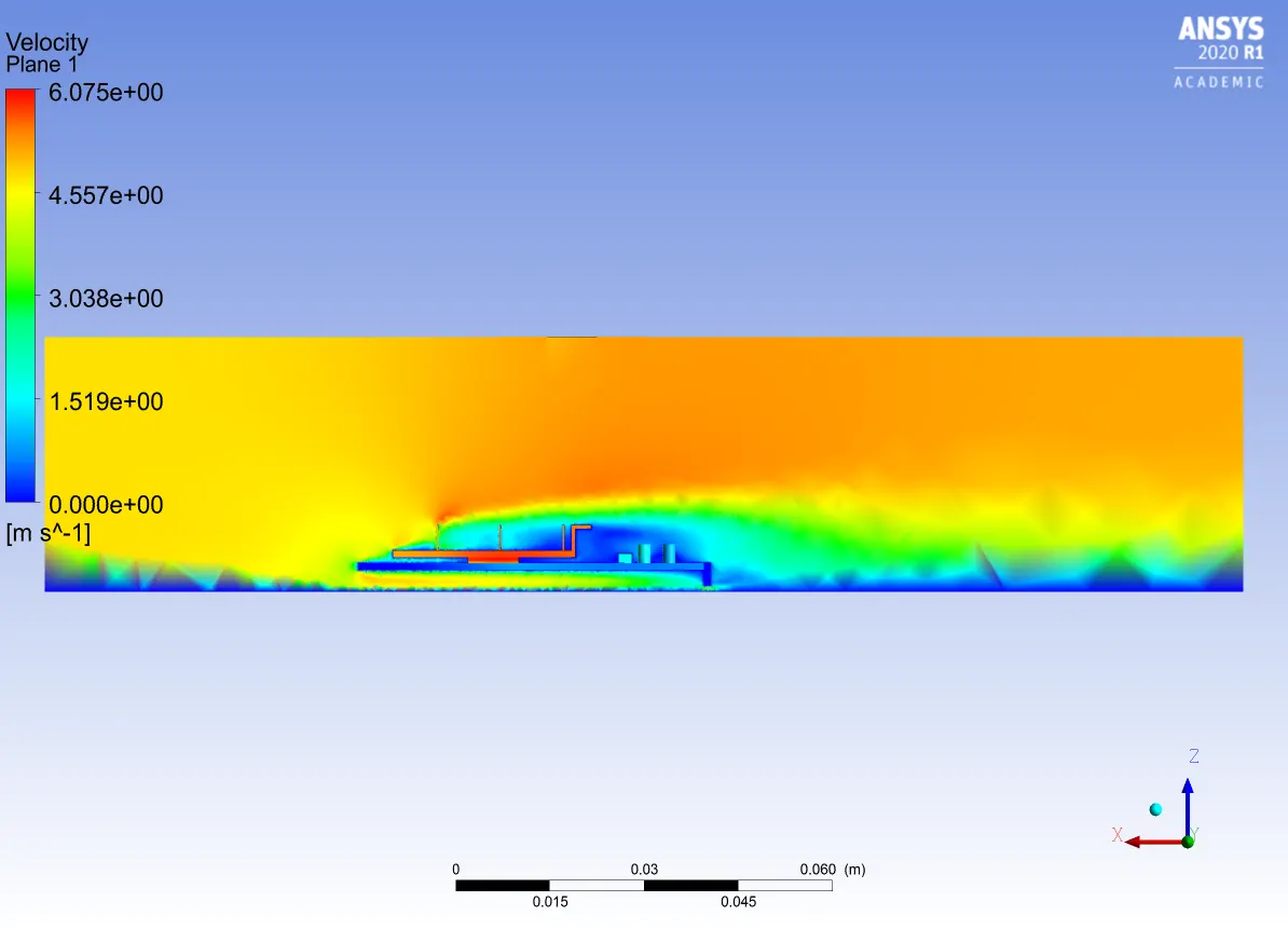
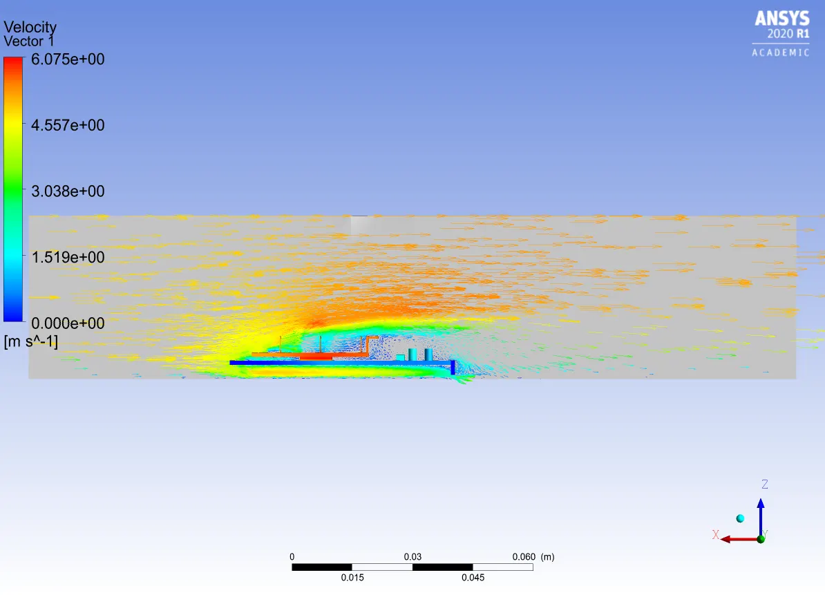
Vwelocity:-
CONCLUSION AND OBSERVATIONS:-
- CHT analysis is done on the graphic card and results are noted down.
- Simulation have converged at 70 iterations in refined case and 60 iterations in the baseline mesh.
- We can confirm the convergence by residual plots.
- The main hotspot is the processor as it is generating all the heat anmd next is fins which is taking the heat and cooling the processor by freestram air.
- We can xclearly sse that the temperature is cooling down at the backside off the base.
- For more clarification I have tabulated the results.
| Case | Velocity-input(m/s) | Maximum Temperature (k) |
|
Maximum Velocity | Mesh | |
| 1 | 1 | 341.6 | 1217 | 1.164 | Baseline | |
|
2 |
1 | 373.3 | 663.9 | 1.241 | Refined | |
| 3 | 2.5 | 321.4 | 663.9 | 3.173 | Refined | |
| 4 | 4.8 | 314.8 | 663.9 | 6.075 | Refined |
- From the above results we can see that the baseline mesh is not at all worth of simulating for this type of geometry or analysis.
- So in the refined case we can see that the when the velocity is increased the tempearture is going down slightly and also the maximum velocity is increased at the end.
- The wall heat transfer is captured only when the mesh is refined properly.