Conjugate Heat Transfer Analysis on a graphics card.
Aim: To perform steady-state conjugate heat transfer analysis on graphics card by varying air velocity.
Introduction and Theory: CHT(Conjugate Heat Transfer) corresponds to the heat transfer in solids and heat transfer in fluids. In solids, conduction often dominates and in fluids, convection dominates.CHT analysis allows us to analyze heat transfer between a solid domain and a fluid domain. We can simulate the flow of fluids of any velocity, temperature, physical and chemical property through or around a solid of any shape, size, physical, and chemical property. This, allows us to analyze the heat transfer characteristics at the interface between both the domains.
Running a CHT simulation requires a multi-region mesh with shared topology between solid and fluid domains. This is to ensure the smooth transfer of information(heat transfer) at the interface.
CHT analysis is beneficial in accurately predicting solid temperatures and heat transfer capabilities in engineering devices. Using CHT analysis, engineers can optimize the thermal characteristics of the product.
Applications: HVAC, Internal Combustion Engine, Gas Turbines, Heat Exchangers
Modeling Approach:
Pre-Processing:
Step 1: Importing geometry
The prepared design of graphics card was imported into Spaceclaim, and the topology was set to share, to achieve conformal mesh at solid and fluid interface. The design also consists of an enclosure that surrounds the graphic card.
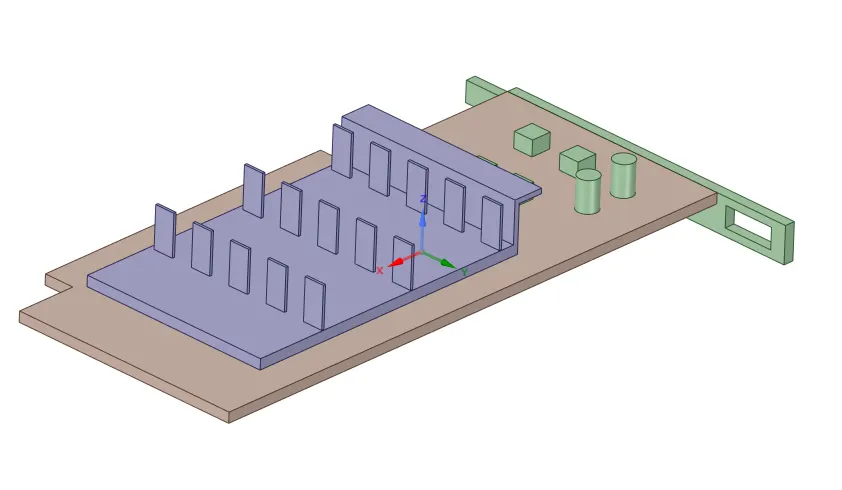
Fig1. Graphics Card Geometry
Step 2: Meshing
The mesh which was created is depicted below:
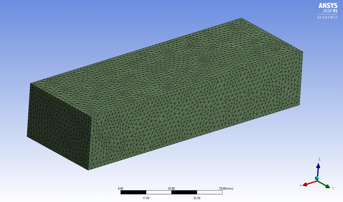
Fig2. Enclosure mesh
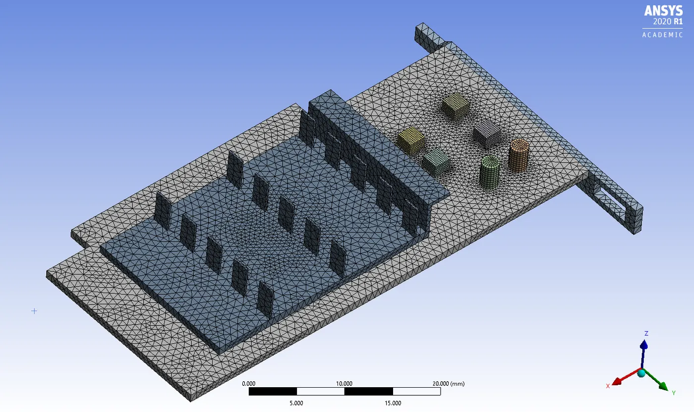
Fig3. Graphic Card mesh
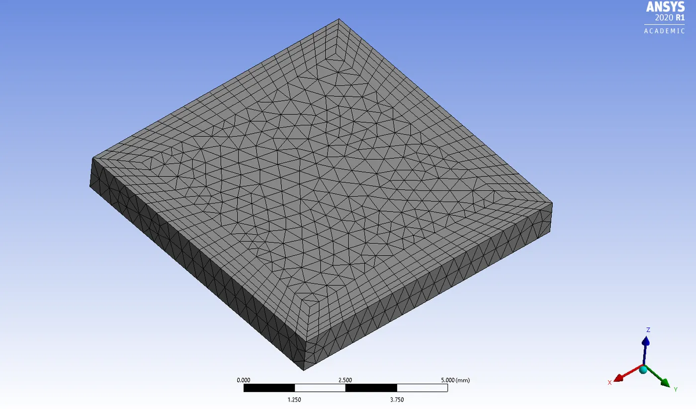
Fig4. Processor mesh
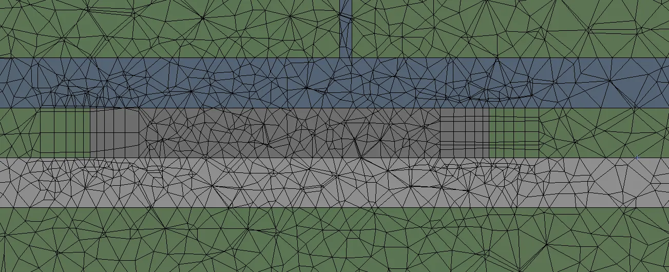
Fig5. Image depicting inflation layer around the processor into the fluid domain
Mesh Properties:
Global Element size: 3mm
Statistics:

Body sizing was applied to fins, processor and base.
Body sizing on fins : 0.8 mm
Body sizing on processor: 0.4 mm
Body sizing on base : 0.8 mm
Edge sizing was applied to the cylinders and cubes on the base : 10 divisions
Inflation layer was generated on the processor, with a total thickness of 1 mm , corresponding to a Y+ value of 0.6 which is necessary to be coupled with a K-omega SST model. This was done to properly capture the HTC(Heat Transfer Coefficient) values.
The above mesh setting was chosen because we have a limit on the cell count in academic license and we cant have refined mesh in all the regions. Therefore, regions of interest, such as the processor , fins and base were refined according to requirements.
Step 3: Solving using Fluent
Solver - Pressure based, steady-sate solver with Absolute velocity formulation
Viscous model - k-omega SST
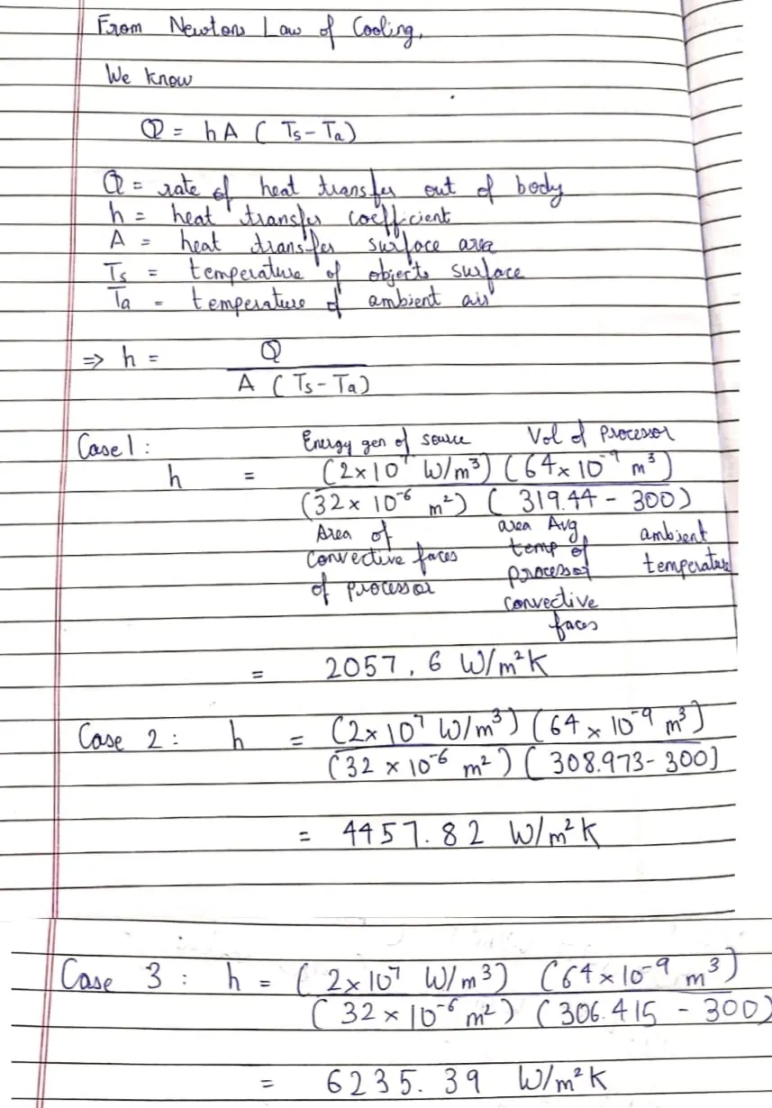
Energy source = 2*10^7 `W/m^3` given to processor
Material Properties:
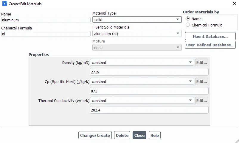
Material of base, processor and fins (Solid domain): Aluminium
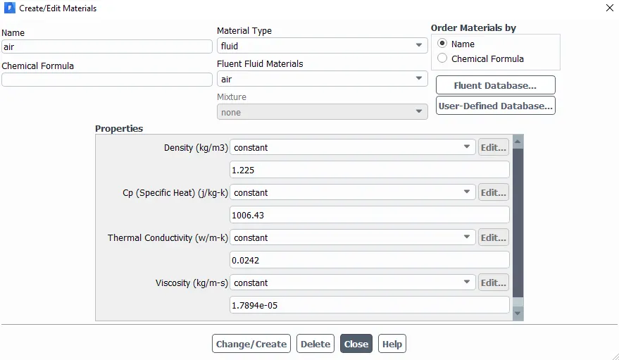
Material of enclosure (fluid domain) : Air
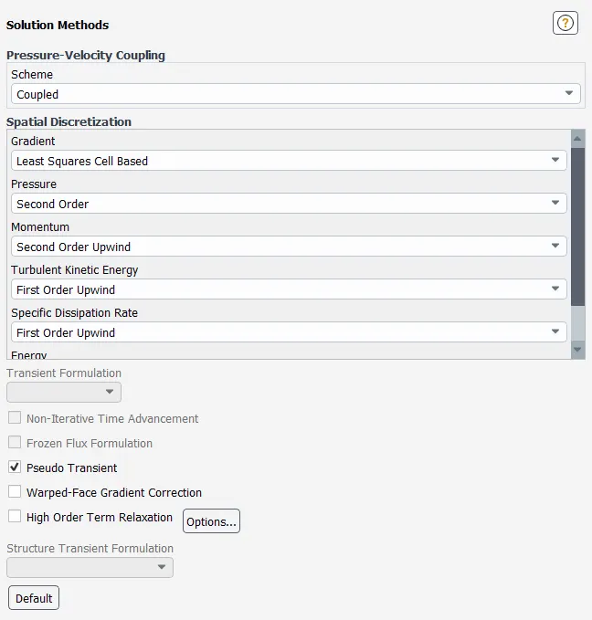
Solution method:
Residuals:
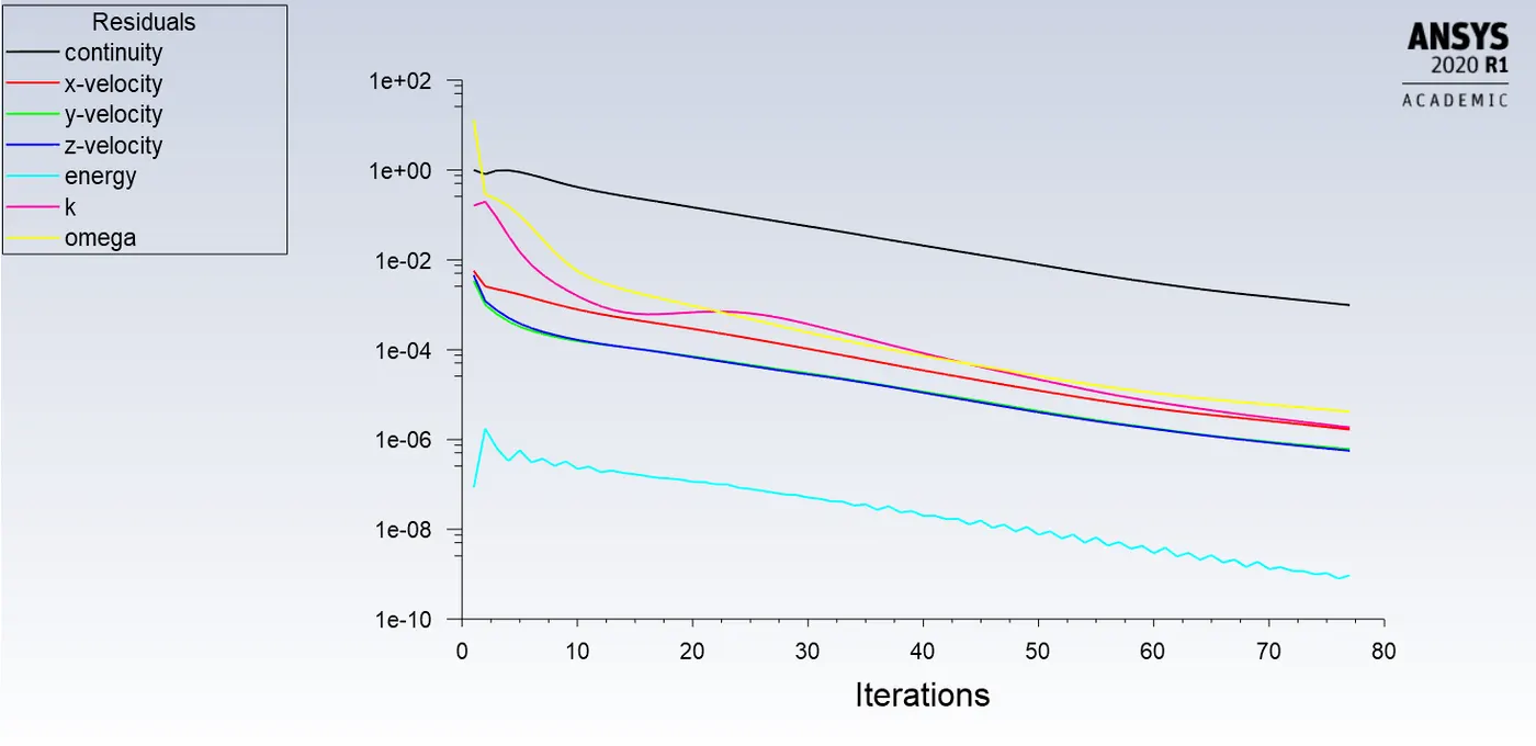
Case 1: Inlet Velocity = 1m/s
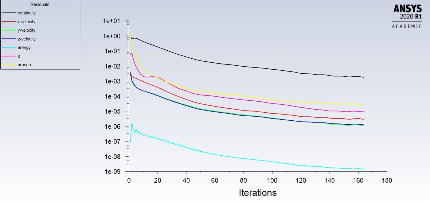
Case 2: Inlet Velocity = 3m/s
Case 3: Inlet Velocity = 5m/s
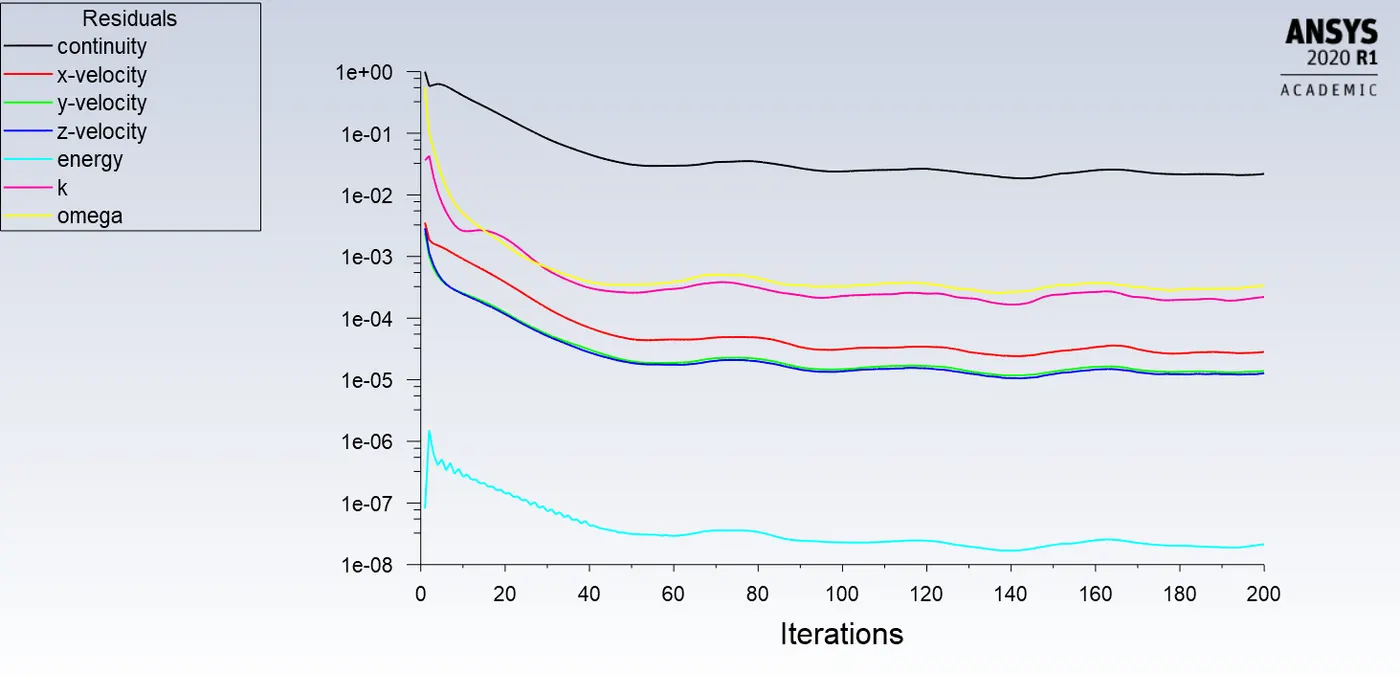
Since the residuals are continously falling we can conclude that the solution has converged.
Results:
Case 1:
1. Max Temperature attained by processor
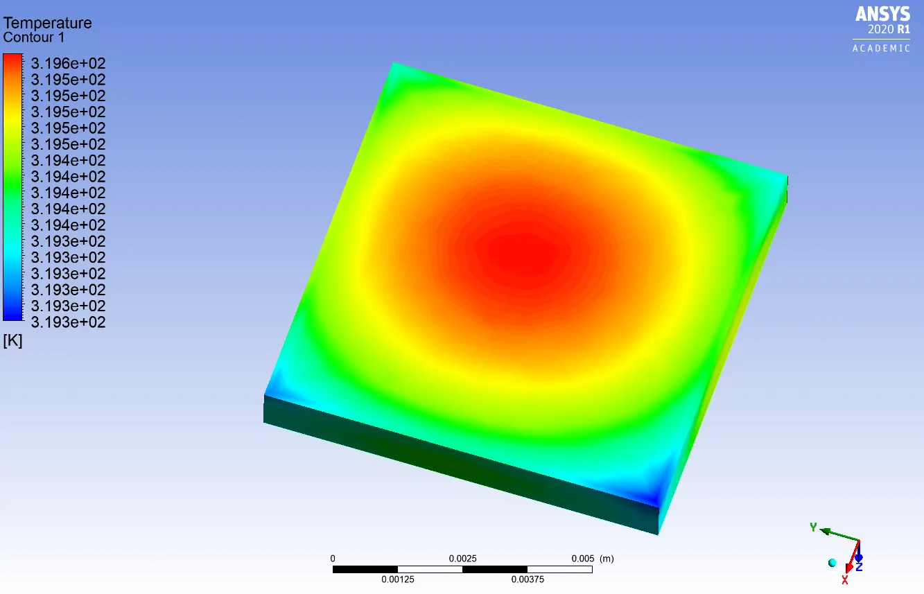
Max temperature attained by the processor is 319.6 K
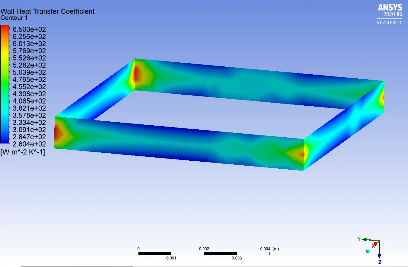
2. Max HTC attained by processor
3. Potential Hotspots
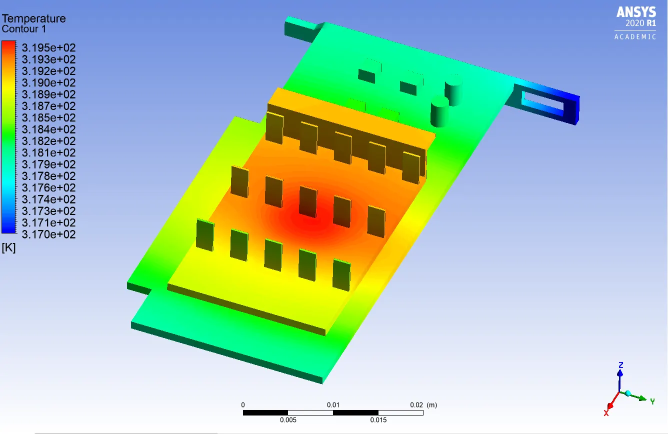
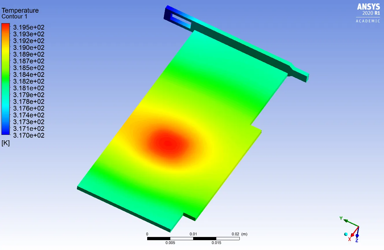
Case 2:
1. Max Temperature attained by processor
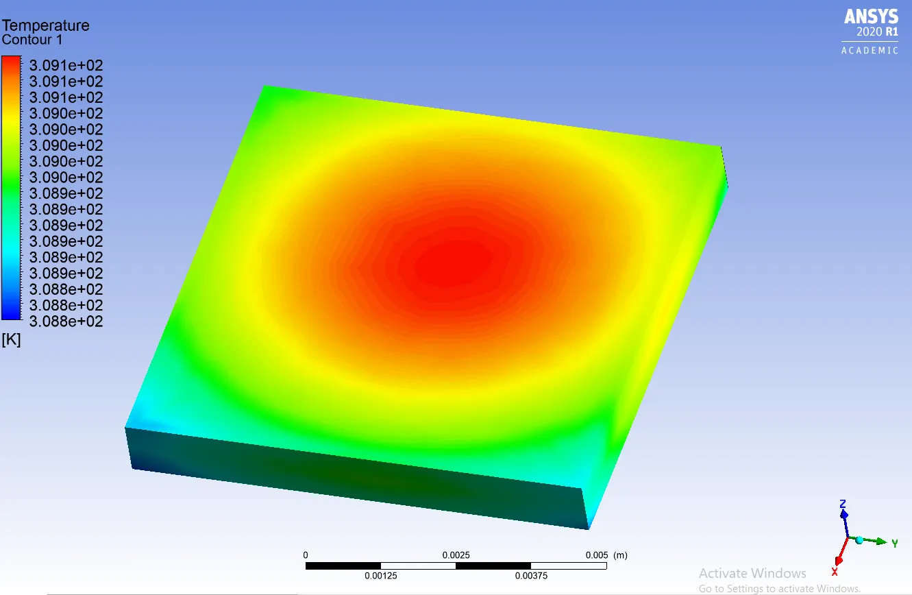
Max temperature attained by the processor is 309.1 K
2. Max HTC attained by processor
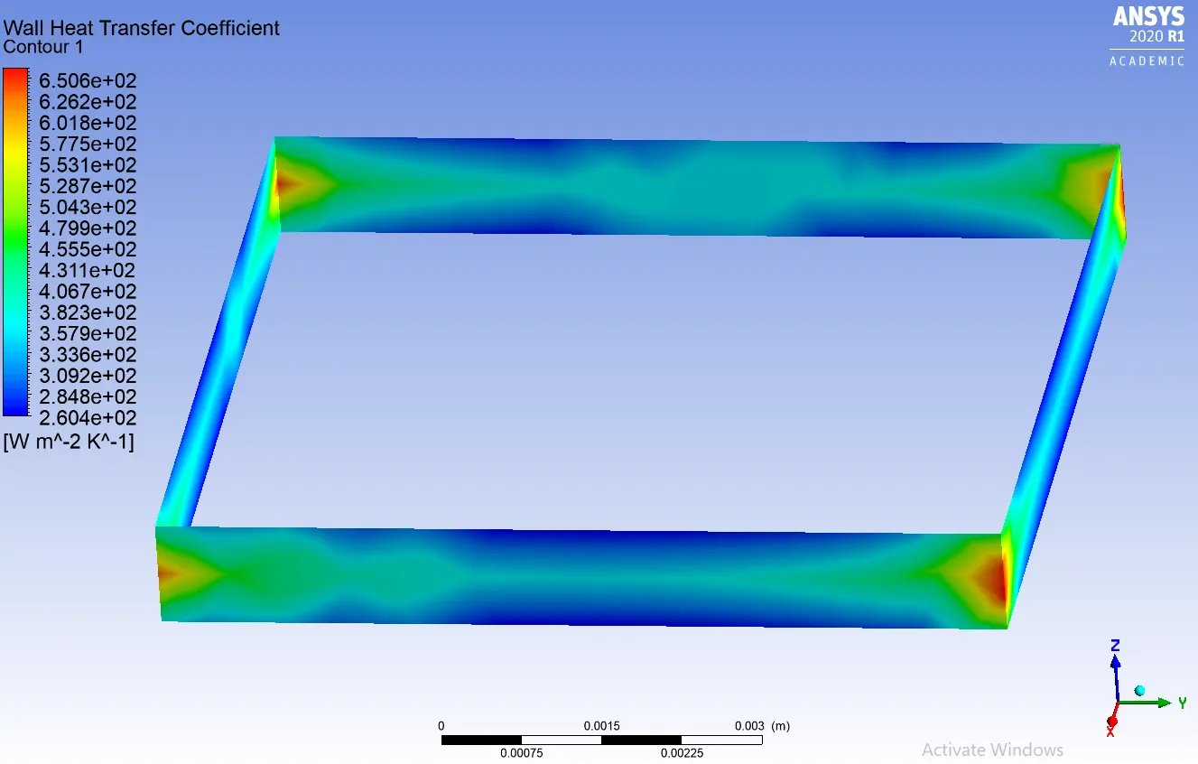
3. Potential Hotspots
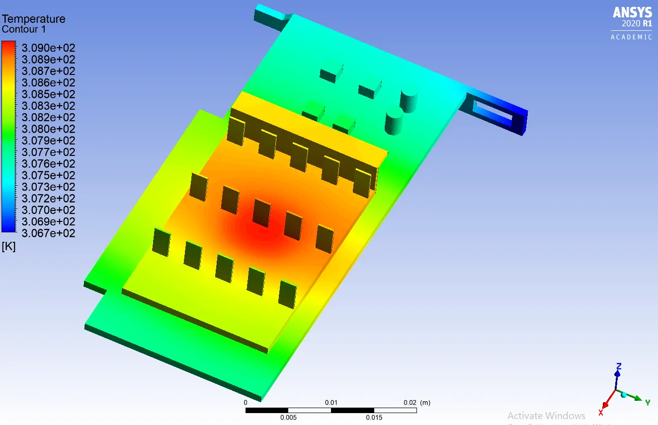
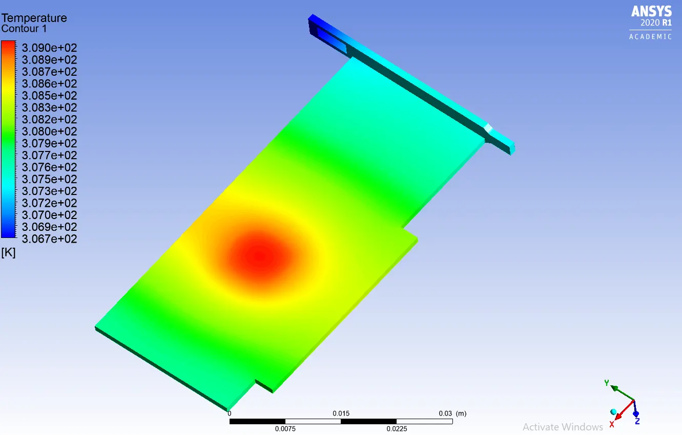
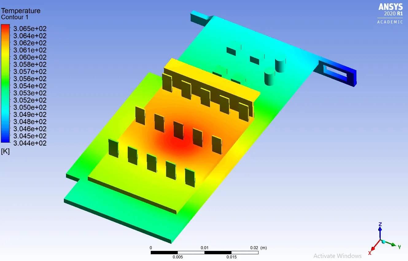
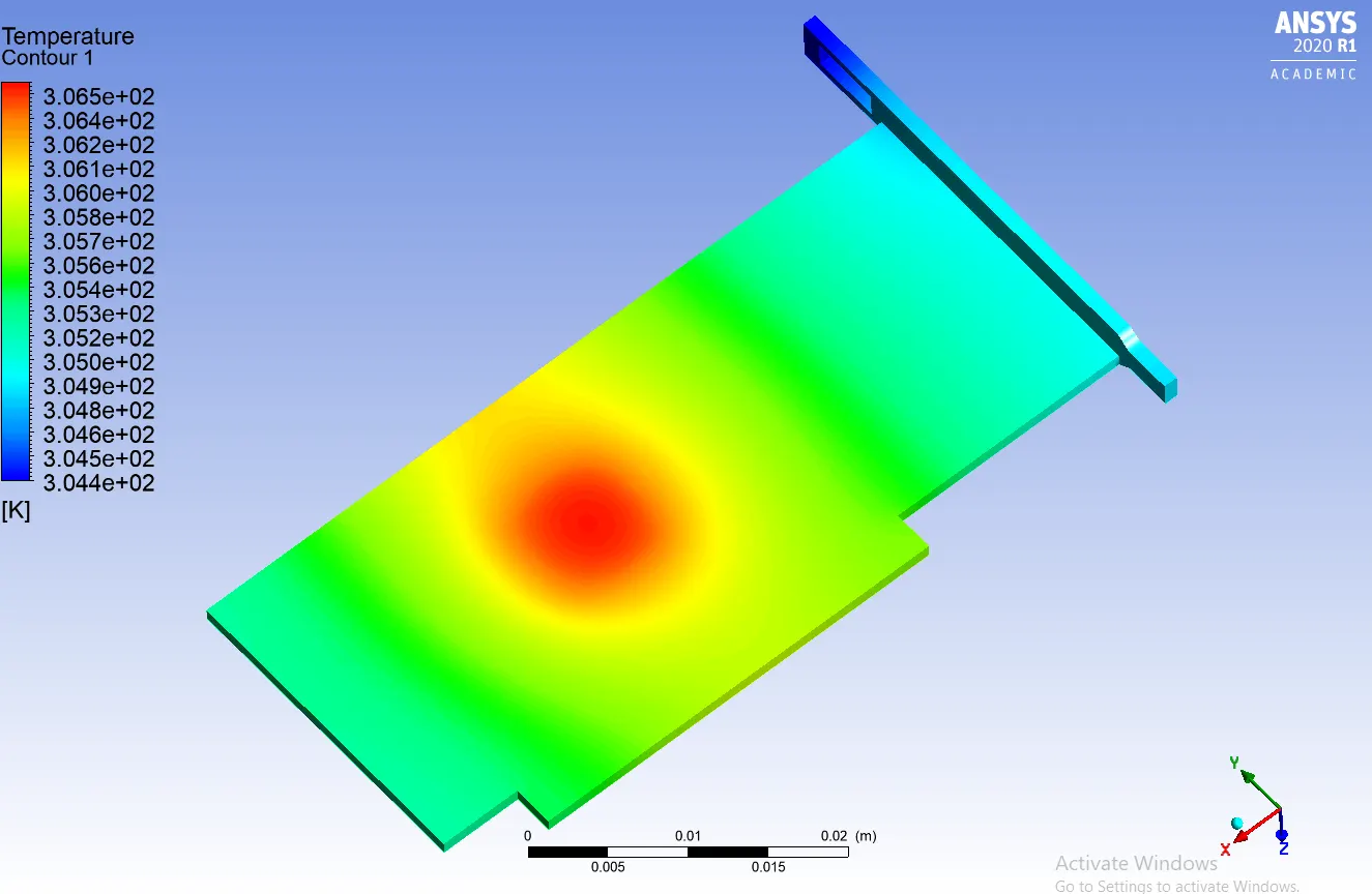
Case 3:
1. Max Temperature attained by processor
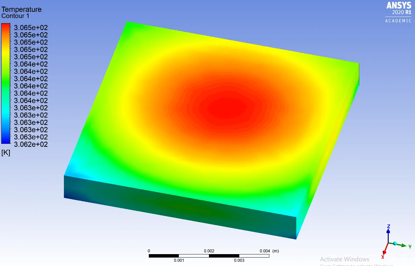
Max temperature attained by the processor is 306.5 K
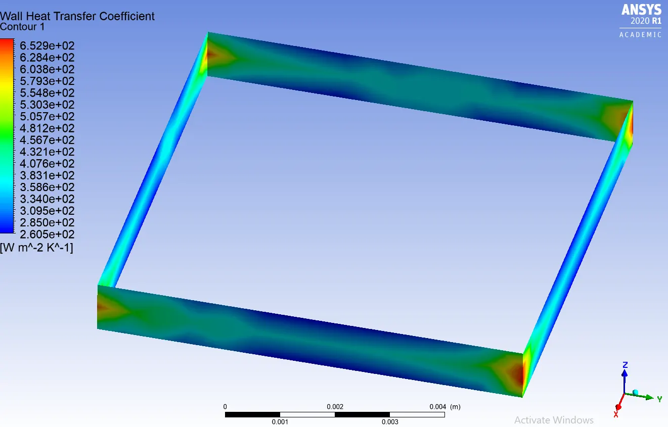
2. Max HTC attained by processor
3. Potential Hotspots
Manual Calculation of HTC values:
Conclusion:
1. The maximum temperature at the processor keeps falling as we increase the velocity. However, the rate at which temperature reduces is reduced at higher air velocities.
2. The HTC values also increase with increasing air velocity.
3.The potential hotspot can be seen in the processor-fins and processor-base interface. Since they are carrying heat away from the processor.
Thus this simulation can help us get an insight into designing the graphics card processor heat transfer requirements in a system, thus helping us to decide fan speed, fins effectiveness in transferring heat away from the processor, and placement of the components in such a way to get maximum heat transfer.