Conceptual design of a building with columns and shear walls
Question 1:
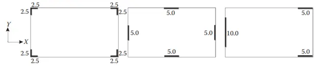
The building shown, 20 × 35 m in plan, has columns on a 5 × 5 m grid and shear walls (with dimensions shown in m, 250 mm in thickness) in three alternative arrangements, (a), (b), (c), all with the same total cross-sectional area of the shear walls. Compare the three alternatives, taking into account the restraint of floor shrinkage, the lateral stiffness and the torsional one with respect to the vertical axis, the vertical reinforcement required for the same total flexural capacity at the base, the static eccentricity, the system’s redundancy, foundation systems, architectural constraints etc.
Answer:
1. Floor Shrinkage Restraint
-
(a): Walls at corners → allow uniform shrinkage, minimal restraint.
-
(b): Walls at mid-spans of perimeter → more restraint on slab shrinkage and potential cracking.
-
(c): Asymmetrical wall distribution → significant restraint on one side, can lead to differential shrinkage cracks.
Best: (a) (minimal shrinkage restraint).
2. Lateral Stiffness
-
(a): Shear walls are located far apart, giving maximum stiffness in both X and Y directions due to large lever arms.
-
(b): Walls in center → moderate stiffness.
-
(c): Concentrated walls on one side → high stiffness in Y, but low in X; torsion is a major concern.
Best for lateral stiffness: (a)
3. Torsional Resistance (about vertical axis)
-
(a): Symmetrical wall layout → minimal torsional effects.
-
(b): Still fairly symmetrical.
-
(c): Highly unsymmetrical → severe torsional rotation under lateral seismic loads.
Best: (a)
Worst: (c)
4. Flexural Reinforcement Requirement
-
Assumption: Total wall area is constant in all 3 cases.
-
Flexural capacity , where d = distance from compression to tension face.
-
(a): Largest moment arm due to far placement → least reinforcement needed.
-
(b): Moderate arm → more steel.
-
(c): Smallest lever arm → highest steel demand for the same capacity.
Most efficient: (a)
5. Static Eccentricity
-
(a): Symmetrical wall layout → negligible eccentricity.
-
(b): Nearly symmetrical.
-
(c): Asymmetrical → large static eccentricity, leads to twisting.
Best: (a)
Worst: (c)
6. System Redundancy
-
(a): Multiple walls, well distributed → good redundancy.
-
(b): Redundancy is moderate.
-
(c): Low redundancy due to localized concentration of walls.
Best: (a)
7. Foundation System Requirements
-
(a): Walls at corners → simple isolated footings or tied combined footings.
-
(b): Walls in middle → central footings may affect basements/utilities.
-
(c): High concentration on one side → large foundation moments, requires strong raft/mat footing or deep piles.
Most economical: (a)
Most complex: (c)
8. Architectural Constraints
-
(a): Corners used for walls → may interfere with façade, but typically manageable.
-
(b): Wall placement at mid-sides → greater interior space flexibility.
-
(c): Walls concentrated on one side → blocks usable space, limits design.
Best balance: (b)
Conclusion (Comparison Table)
| Criteria | (a) Corner Walls | (b) Mid Walls | (c) One Side Walls |
|---|---|---|---|
| Floor Shrinkage Restraint | ✅ Best | ❌ Moderate | ❌ Poor |
| Lateral Stiffness | ✅ High | ⚠️ Medium | ❌ Poor in X, torsion in Y |
| Torsional Resistance | ✅ Excellent | ✅ Good | ❌ Very Poor |
| Flexural Reinforcement | ✅ Least Needed | ⚠️ More | ❌ Most |
| Static Eccentricity | ✅ Minimal | ✅ Low | ❌ High |
| System Redundancy | ✅ High | ⚠️ Moderate | ❌ Low |
| Foundation Requirements | ✅ Simple | ⚠️ Medium Complexity | ❌ Complex |
| Architectural Impact | ⚠️ Slight | ✅ Flexible | ❌ Restrictive |
Best All-Round Choice: ✅ Option (a)
Question 2:
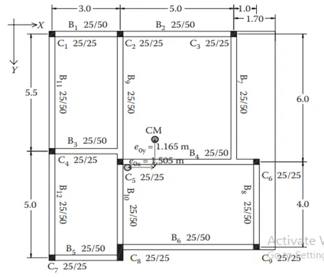
Discuss the suitability for earthquake resistance of the moment resisting framing plan of a three-storey building depicted here (cross-sectional dimensions in cm), the eccentricity of the centre of mass (as centroid of floor plan) to the centre of stiffness (from the moments of inertia of the columns) are shown. Suggest an alternative. Also, is there torsional flexibility? Are the two fundamental translational modes of vibration larger than the fundamental torsional mode of vibration. Discuss qualitatively.
Answer:
1. Suitability for Earthquake Resistance
Overview of the Framing Plan
The diagram shows a floor plan of a three-stored building with a moment resisting frame. The plan has:
· Dimensions: 5.0 m × 6.0 m (X and Y directions, respectively).
· Columns: Located at the corners and midpoints of the perimeter, labelled C₁ to C₈, each with a cross-section of 25 cm × 25 cm (0.25 m × 0.25 m).
· Beams: Labelled B₁ to B₈, with cross sections of 25 cm × 50 cm (0.25 m × 0.50 m).
· Centre of Mass (CM): At (1.65 m, 2.05 m) from the bottom left corner.
· Centre of Stiffness (CS): At (2.50 m, 3.00 m), which is the geometric centroid of the column layout (since columns are symmetrically placed and have identical cross sections).
· Eccentricity:
o ex =2.50−1.65=0.85m
o ey =3.00−2.05=0.95m
Earthquake Resistance Assessment
· Moment resisting frames (MRFs) are generally suitable for earthquake resistance because they provide ductility and can dissipate energy through plastic hinge formation in beams and columns. However, the given plan has some concerns:
· Eccentricity between CM and CS: The significant eccentricity (0.85 m in X, 0.95 m in Y) indicates that the centre of mass (where seismic forces act) is offset from the center of stiffness (where resistance is provided). This leads to torsional effects during an earthquake, causing uneven distribution of forces among the columns. Columns farther from the CM (e.g., C₁, C₄) will experience higher forces, potentially leading to failure.
· Symmetry and Column Distribution: The columns are symmetrically placed, which is good for stiffness distribution, but the eccentricity suggests an uneven mass distribution (possibly due to heavier equipment, walls, or asymmetric loading on one side). This asymmetry exacerbates torsional effects.
· Column and Beam Sizes: The columns (25 cm × 25 cm) are relatively small for a three-story building under seismic loading, especially if the building is in a high seismic zone. The beams (25 cm × 50 cm) are deeper, which is good for moment resistance, but their capacity to handle shear and moment demands needs to be checked. Small column sizes may lead to inadequate stiffness and strength, increasing the risk of buckling or failure under lateral loads.
· Active C25 Setting: The note “Active C25 Setting” likely refers to the concrete grade (C25, with a characteristic compressive strength of 25 MPa). This is a moderate strength concrete, suitable for low to moderate seismic zones, but may be insufficient for high seismic zones where higher ductility and strength (e.g., C30 or C40) are preferred.
Conclusion on Suitability
The moment resisting frame has potential for earthquake resistance due to its inherent ductility, but the significant eccentricity and relatively small column sizes make it less suitable, especially in a high seismic zone. The eccentricity will induce torsional vibrations, increasing the risk of damage to columns on one side of the building. Additionally, the concrete grade and column sizes may not provide sufficient strength and ductility for severe seismic events.
2. Torsional Flexibility
· Torsional flexibility arises when the center of mass and center of stiffness do not coincide, leading to a twisting motion during seismic excitation.
· Eccentricity and Torsion: The given eccentricities (𝑒𝑥 = 0.85m e x =0.85m, 𝑒𝑦 = 0.95m e y =0.95m)
· confirm that the building will experience torsional effects. The magnitude of these eccentricities is significant relative to the building dimensions (5.0 m × 6.0 m), indicating high torsional flexibility.
· Column Layout: The columns are placed only on the perimeter, with no interior columns. This layout provides less torsional stiffness compared to a layout with interior columns, as the perimeter only arrangement has a lower polar moment of inertia about the vertical axis. The building is more prone to twisting, especially given the eccentric mass distribution.
· Conclusion: Yes, the structure exhibits torsional flexibility due to the eccentricity and perimeter only column layout. This flexibility will amplify torsional vibrations during an earthquake, potentially leading to uneven force distribution and increased damage risk.
3. Comparison of Fundamental Modes of Vibration
To qualitatively compare the fundamental translational modes (in X and Y directions) with the fundamental torsional mode, we need to consider the building’s stiffness and mass distribution.
Fundamental Translational Modes
·
X-Direction Translation: Stiffness in the
X-direction depends on the columns’ resistance to bending in the XZ plane.
There are 5 columns along each X-direction edge (e.g., C₁, C₂, C₃ on the top
edge), each with a moment of inertia  The total
stiffness is proportional to the sum of the column stiffnesses, and the period
of vibration is inversely proportional to the square root of stiffness.
The total
stiffness is proportional to the sum of the column stiffnesses, and the period
of vibration is inversely proportional to the square root of stiffness.
· Y-Direction Translation: Similarly, in the Y direction, there are 4 columns per edge (e.g., C₁, C₄ on the left edge), with the same moment of inertia. The Y direction stiffness is slightly lower due to fewer columns resisting in that direction.
· The mass is the same for both directions (assuming uniform floor mass, despite the CM offset). The translational periods Tx and 𝑇𝑦 are typically close, but Ty may be slightly larger due to lower stiffness in the Y-direction.
Fundamental Torsional Mode
· The torsional stiffness depends on the polar moment of inertia of the column layout about the vertical axis through the CS. Since the columns are on the perimeter, their contribution to torsional stiffness is higher than if they were closer to the center, but the lack of interior columns reduces overall torsional rigidity.
· The mass moment of inertia about the vertical axis is influenced by the eccentric mass distribution. The eccentricity increases the effective mass moment of inertia for torsion, leading to a longer torsional period.
· The torsional period Tθ is typically larger than the translational periods in structures with significant eccentricity because torsional stiffness is often lower than translational stiffness, and the mass moment of inertia is amplified by the eccentricity.
Qualitative Comparison
· In a typical building, the translational periods (Tx, 𝑇𝑦) are shorter than the torsional period Tθ because translational stiffness is generally higher than torsional stiffness, especially in a perimeter frame system like this one.
· Given the large eccentricity (0.85 m, 0.95 m), the torsional period is further increased due to the higher mass moment of inertia. Therefore, it is likely that the two fundamental translational modes (Tx, 𝑇𝑦) have periods smaller than the fundamental torsional mode Tθ.
Conclusion: Qualitatively, the fundamental translational modes of vibration are likely to have shorter periods (i.e., higher frequencies) than the fundamental torsional mode, due to the lower torsional stiffness and the effect of eccentricity on the torsional mass moment of inertia.
4. Suggested Alternative Design
To improve earthquake resistance and reduce torsional effects, consider the following alternative:
Reduce Eccentricity:
Relocate heavy equipment, partitions, or loads to bring the center of mass closer to the center of stiffness (2.50 m, 3.00 m). This may involve redesigning the floor plan to ensure a more uniform mass distribution.
Alternatively, adjust the stiffness by adding columns or shear walls strategically to shift the CS closer to the CM.
Add Interior Columns or Shear Walls:
Introduce interior columns (e.g., at the center of the plan) to increase overall stiffness and reduce torsional flexibility. This would also help distribute seismic forces more evenly.
Alternatively, add shear walls along the X and Y directions (e.g., between C₁C₄ and C₂C₅). Shear walls provide high lateral stiffness and strength, significantly improving earthquake resistance and reducing torsional effects.
Increase Column Sizes:
Increase the column cross sections (e.g., to 30 cm × 30 cm or larger) to provide greater stiffness and strength, especially for a three-story building in a seismic zone.
Use Higher Grade Concrete:
Upgrade to a higher strength concrete (e.g., C30 or C40) to improve the structure’s ductility and capacity to resist seismic forces.
Alternative System: Consider a dual system combining a moment resisting frame with shear walls or braced frames. This hybrid approach provides both ductility (from the MRF) and high stiffness (from shear walls or braces), making it more suitable for seismic zones.
Example Alternative Layout:
· Add a shear wall along the left edge (C₁-C₄) and top edge (C₁-C₃) to increase stiffness in both directions.
· Add one interior column at the center (2.50 m, 3.00 m) with a larger cross section (e.g., 30 cm × 30 cm).
· Redistribute mass to minimize eccentricity, aiming for ex and ey to be less than 0.3 m.
This design would reduce torsional effects, increase overall stiffness, and improve the building’s ability to resist seismic forces.
Final Summary
· Earthquake Resistance: The moment resisting frame is moderately suitable but compromised by significant eccentricity (0.85 m, 0.95 m) and small column sizes, leading to torsional issues and potential column overloading.
· Torsional Flexibility: The structure is torsionally flexible due to the eccentricity and perimeter only column layout, increasing the risk of twisting during an earthquake.
· Modes of Vibration: The fundamental translational modes likely have shorter periods than the torsional mode, due to lower torsional stiffness and the effect of eccentricity.
· Alternative: Reduce eccentricity by redistributing mass or stiffness, add interior columns or shear walls, increase column sizes, and use higher grade concrete. A dual system with shear walls is recommended for better seismic performance.
Question 3:
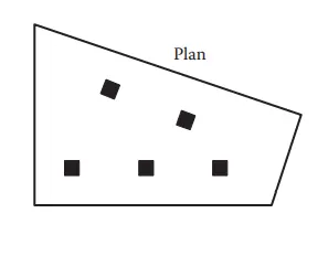
A multi-storey building with basement, with a quadrilateral (non symmetrical floor plan) plan as, has interior columns in an irregular (not in a grid) pattern in plan that serves architectural and functional considerations. Partition walls and interior beams supporting the slab have different layout in different stories. However, there is no constraint to the type, location and size of the lateral force resisting components and sub-systems on the perimeter. Proposals are to be made and justified for the choice of the lateral-load-resisting system and its foundation.
Answer:
Overview:
The given multi-storey building has:
-
A non-symmetrical quadrilateral plan.
-
Interior columns placed irregularly, not on a grid.
-
Partition walls and beams differ by floor.
-
Perimeter locations are available for lateral-force-resisting systems.
Thus, the key challenges involve:
-
Plan irregularity,
-
Non-uniform vertical stiffness and mass distribution,
-
Potential for torsional irregularities, and
-
Need for a robust seismic load path.
Proposed Lateral Load Resisting System:
1. Dual System – RC Shear Walls + Moment-Resisting Frames
A combination of:
-
RC Shear Walls along the perimeter, and
-
Moment-Resisting Frames integrated into the layout.
This hybrid system enhances both lateral stiffness and ductility.
2. Perimeter Shear Walls
-
Place continuous vertical RC shear walls along all four sides of the building.
-
Orient walls to resist both X and Y direction seismic forces.
-
Use C-shaped or L-shaped shear walls at corners if possible for torsional resistance.
Shear walls at the perimeter help reduce torsional rotation and control inter-storey drift.
3. Moment-Resisting Frames
-
Use moment frames along internal lines, especially where architectural openings exist.
-
Provide continuity between floors for energy dissipation.
-
Frames help resist secondary moments, and enhance ductility and redundancy.
Vertical Irregularities (Due to Partitions and Beams):
-
Maintain vertical alignment of structural elements.
-
Use coupling beams between shear walls where wall segments are discontinuous.
Avoid soft-storey behavior by ensuring uniform stiffness floor-to-floor.
Foundation Proposal:
Given that the structure is a basement + multi-storey, foundation must handle:
-
High vertical + lateral loads,
-
Torsional moments,
-
Basement lateral earth pressure.
Recommended Foundation:
-
Raft Foundation with Thickened Zones under Shear Walls and Core Walls, OR
-
Pile-Raft Foundation for poor soil conditions.
Raft ensures uniform load distribution and helps counter torsional moments from irregular load paths.
Justification for Proposal:
| Design Challenge | Mitigation Strategy |
|---|---|
| Irregular plan | Shear walls at perimeter reduce torsion |
| Non-grid interior columns | Perimeter-based system avoids irregular frame spacing |
| Vertical irregularities | Continuity via shear walls and coupling beams |
| Asymmetric mass distribution | Torsional stiffness via symmetric wall layout |
| Basement lateral loads | Raft or pile-raft handles seismic + soil pressure |
Conclusion:
The proposed Dual System (Shear Walls + Moment Frames) with a Raft or Pile-Raft Foundation:
-
Meets architectural constraints,
-
Provides high seismic performance,
-
Controls torsion and drift, and
-
Allows for design flexibility.