Conceptual design of a building with columns and shear walls
Question 1 :
The building shown, 20 × 35 m in plan, has columns on a 5 × 5 m grid and shear walls (with dimensions shown in m, 250 mm in thickness) in three alternative arrangements, (a), (b), (c), all with the same total cross-sectional area of the shear walls. Compare the three alternatives, taking into account the restraint of floor shrinkage, the lateral stiffness and the torsional one with respect to the vertical axis, the vertical reinforcement required for the same total flexural capacity at the base, the static eccentricity, the system’s redundancy, foundation systems, architectural constraints etc.
Answer :
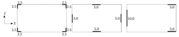
Type 1 Type 2 Type 3
Criteria for type 1 :
1.Restraint of Floor shrinkage:
Since all four corners of floor is restricted to experience shortening, this RC wall system possess good control of shrinkage.
2.Lateral Stiffness:
During earthquake excitation, the principle directions will be exposed to lateral movements. At such incidents, since the given RC wall system is not across the principle planes but in diagonal location. So it will possess less stiffness.
3.Torsion with vertical axis:
Center of mass and center of stiffness will coincide. So less prone to Torsion.
4.Vertical rebar at Base:
As they will experience lesser lateral forces, the amount of reinforcement may be lesser than other systems.
5.Static eccentricity:
The system is centric with respect to mass-stiffness comparison.
6.System’s redundancy:
Since the RC wall is less effective to collect lateral forces, the frame structures will need to take part in lateral load resisting system.
7.Foundation system:
Isolated footing with tie beam arrangement is suitable for this system.
8.Architectural constraints:
Architecturally very effective, since only corners are obstructed.
Criteria for Type 2:
Restraint of floor shrinkage :
The edges of Floor are restricted to floor shortening. Whereas the corners are prone to shortening/shrinkage with frame system.
Lateral stiffness:
The RC walls are right across the lateral force direction. They possess better stiffness compared to other systems.
Torsion with vertical axis:
Center of mass and center of stiffness will coincide. So less prone to Torsion.
Vertical rebar at base:
This system will take all lateral loads in either principle directions. So the amount of vertical rebar will be heavier than the previous system.
Static ecentricity:
The system is centric with respect to mass-stiffness comparison.
Systems redundancy:
RC wall system is effective in this case and mirror with right angle. They possess good redundancy.
Foundation system:
Box type foundation is suitable for this system.
Architectural constraints :
Architecturally may not be recommended since all four side entrances are partially obstructed. This RC wall arrangement may disturb open space requirement.
Criteria for type 3:
Restraint of floor shrinkage:
In both the principle directions, the floor is not enclosed with RC wall system at two sides. So this floor will have more shrinkage effect.
Lateral stiffness:
The RC wall system is effective and stiffer in X-direction. But not stiffer in Y-direction due to concentration of RC wall at only one side.
Torsion with vertical axis:
Center of mass and center of stiffness will not coincide in both the principle directions. So this system will experience more torsion during earthquake.
Vertical rebar at Base:
The RC wall arrangement is so eccentric that these walls will experience extreme lateral and torsional moments. This system will have the highest amount of vertical rebar.
Static ecentricity:
The system is more eccentric with respect to mass-stiffness comparison.
Systems redundancy:
The system is worst in terms of redundancy because of concentration of load at one sides.
Foundation system:
Strip footing for Y-direction RC wall and isolated footing for X-direction RC wall is suitable.
Architectural Constarints:
Left side is completely arrested. All other sides are okay with respect to architectural point of view.
Question 2:
Discuss the suitability for earthquake resistance of the moment resisting framing plan of a three-storey building depicted here (cross-sectional dimensions in cm), the eccentricity of the centre of mass (as centroid of floor plan) to the centre of stiffness (from the moments of inertia of the columns) are shown. Suggest an alternative. Also, is there torsional flexibility? Are the two fundamental translational modes of vibration larger than the fundamental torsional mode of vibration. Discuss qualitatively.
Answer:
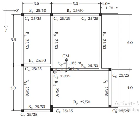
There is a two way eccentricity in the frame along X direction and Y direction also with stiffness the eccentricity in X direction is larger when compared to Y direction.
There is only two continuous frames in the structure that is B1 and B2 in the X direction and B9, B10 and B11,B12 in the Y direction and all other beams are broken at the midway in the frame.
There will be Torsional flexibility in the structure.To avoid torsional restraints it is better to make the room dimensions even in both X and Y direction and placing the columns at the junction of two wall if it is feasible better to provide shear wall at appropriate location.
The fundamental translation mode of vibration is larger than the fundamental torsional mode of vibration.
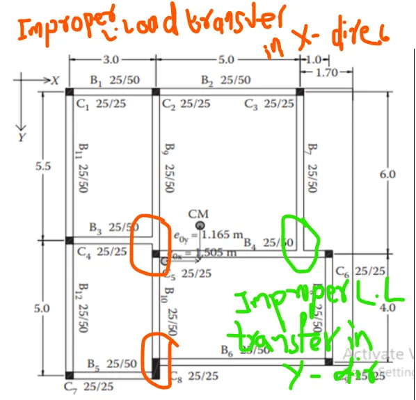
Torsional Flexibility:
A building is said to be Torsionally Irregular if
Natural Period of vibration corresponding to the Fundamental Torsional mode of Oscillation >
Those of the first two Translational modes of oscillation along each Principal plan Directions.
Yes,The frame plan may be considered as Torsionally Flexible or Torsionaly Irregular because of the following reasons:
Given,
There is huge eccentricity of the Framing plan
where ex > ey (1.505 > 1.165)
Therefore the Translational mode of Vibration in both Orthogonal horizontal directions >
Torsional mode of Vibration
It is observed that the centre of mass and Centre of stiffness doesn't coincide.
The Deviation from the ideal frame (Conceptual design of Moment resistant frames for Earthquake) are noticed here:
The single plane frame doesn't run continuously from onside of the Building plan to the other.
The Beam doesn't continue straight from span to span.
The Beam axis has offsets to the column between them,which causing the no proper flow of Beam Internal forces through Beam-column joint.
There is no continuity of the Beam longitudinal Bars across the column from one span to the next span,so this bars are terminated at the joint and anchoring is to be done.
There are some Irregularities with the Framing plan:
Re-entrant Corners:
A Building is said to have a Re-entrant corner in any plan direction when;
The structural configuration in plan has a Projection of size >
15% of its overall dimension in that direction
That is A/L > 0.15
here the right side of the Plan is take into consideration 1.7m/9.7m = 0.175
1.7m projection causes the Irregularity
Hampering of Archiectural Constraints:
The Irreguarities which are considered may cause constraints for Architectural designers.
The design is limited for them in making an attractive outlook of the Building.
Strong column Weak Beam mechanism:
The Strong column weak beam mechanism cannot be followed here due to the Irregularities in the Structural configuration.
The lateral stiffness is hampered due to the offsetting of the column positions which causes a soft storey along the height of the Building.
The Alternatives to be considered for this Building are:
Repositioning of columns in the same line by cuuting down the offsets.
Ensuring the eccentricity of the Centre of mass and the Centre of stiffness to coincide.
To design for shear walls without creating more restrictions for architectural constraints.
Question 3:
A multi-storey building with basement, with a quadrilateral (non symmetrical floor plan) plan as, has interior columns in an irregular (not in a grid) pattern in plan that serves architectural and functional considerations. Partition walls and interior beams supporting the slab have different layout in different stories. However, there is no constraint to the type, location and size of the lateral force resisting components and sub-systems on the perimeter. Proposals are to be made and justified for the choice of the lateral-load-resisting system and its foundation.
Answer:
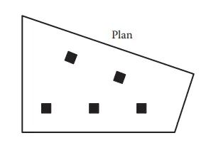
The following given considerations are need to be followed for the Design of appropriate Lateral load system:
A quadrilateral (non symmetrical floor plan) plan:
For this type of system it is observed that there is no symmetry; therefore it has Symmetrical Irregularity.
It has interior columns in an irregular (not in a grid) pattern in plan to serve architectural and functional considerations:
This creates disturbances in the Symmetry as well as it creates Translational and Torsional effects in the Building.
Partition walls and interior beams supporting the slab have different layout in different stories:
This causes huge eccentricity for each storey; which means the centre of mass and centre of stiffness are not near to each other.
In order to neutralize all the above considerations and given that
there is no constraint to the type, location and size of the lateral force resisting components and sub-systems on the perimeter
The Best lateral loading system applicable is the WALL SYSTEM or DUCTILE WALL SYSTEM.
The wall system acts as a Vertical cantilever,not prone to Soft storey mechanism and overshadows all the constraints in the proposal.
Foundation for multi-storey building
The suitable foundation for this type of building is RAFT or MAT foundation only if the Total area of the construction of the footing exceeds 50% of the Total area of the construction site and if the soil has low bearing capacity.
If not, Combined footing is to be provided to make the Centre of gravity and centre of mass coincide.