Conceptual design of a building with columns and shear walls
Question 1:
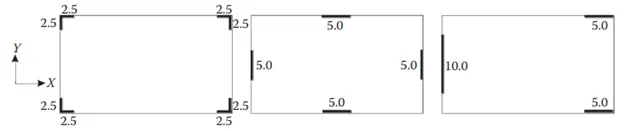
The building shown, 20 × 35 m in plan, has columns on a 5 × 5 m grid and shear walls (with dimensions shown in m, 250 mm in thickness) in three alternative arrangements, (a), (b), (c), all with the same total cross-sectional area of the shear walls. Compare the three alternatives, taking into account the restraint of floor shrinkage, the lateral stiffness and the torsional one with respect to the vertical axis, the vertical reinforcement required for the same total flexural capacity at the base, the static eccentricity, the system’s redundancy, foundation systems, architectural constraints etc.
Answer:
STRCTURE (a)
For this structure is considered as it is asymmetric in nature.
Here cannot to be considered as a horizontal irregularities and the shear wall shape like L.
There is some uncertainty concerning certain features of the seismic response of non-rectangular walls.
It occurs lack of tensile capacity and force configuration.
These walls have high stiffness and strength in both direction, hence are subjected biaxial bending and bi-directional shears during earthquakes.
STRUCTURE (b)
For this structure frame can be considered as symmetric in placed the shear walls.
The walls of a wall system of this frame could be arranged in two horizontal directions with as much two-way symmetric as possible.
The shear walls are arranged in similar and symmetric, so it can be considered at every storey to fairly uniform resistant in seismic forces and deformation demands, minimizing the uncertainty about the seismic response.
STRUCTURE (c)
For this structure can be considered as asymmetric in nature, because of the shear wall are provided are not arranged in a two orthogonal horizontal directons.
The center of mass and center of gravity of such structure will not lie far away from each other enabling transitional modes in the first two principles modes.
The foundation , shear wall and columns are arranged different arrangements, so here take up huge amount moments in case of during earthquakes,
This type of shear wall system will not carry the load equally in either directions. So this structure have lack of redundancy.
On left hand side the wall provide more eccentricity, lateral stiffness is more. Therefore it occurs then the damage or failure will be less.
Design codes define a wall as a vertical element with an elongated cross-section. A lower limit of 4 for aspect ratio (long to short dimension) of a rectangular cross-section is used for a vertical element to be considered as a well.
If the cross-section consists of rectangular parts, one of which has an aspect ratio greater than 4, the element is also classified as a wall.
With this definition on the basis of the cross-sectional shape alone, a wall differs from a column in that it resists lateral forces mainly in one direction (parallel to the long side of the section) and can be designed for such a unidirectional resistance by assigning the flexural resistance to the two edges of the section ('flanges', or 'tension and compression chords') and the shear resistance to the 'web' between them, as in a beam.
In the first figure the L shape walls are given, these walls have high stiffness and strength in both horizontal directions, hence are subjected to biaxial bending and bi-directional sheaars during the earthquake.
They are most cost-effective than the combination of their constituent parts as individual rectangular walls. However, present-day knowledge of their behaviour under cyclic biaxial bending and shear is very limited, and the rules used for their dimensioning and detailing still lack a sound basis.
For this reason, it recommended to make limited use of such walls in practical design. If non-rectangular walls are chosen, they should have a fairy simple section.
The large openings should be avoided in ductile walls, especially near the base, where the plastic hinge forms. If they are necessary for functional reasons (doors and windows), they should not be staggered vertically, but should be arranged at every floor in a regular pattern, creating a coupled wall, with the lintels between the openings serving as coupling beams and designed as such.
The high lateral stiffness of walls reduces inter-storey drifts and structural or non-structural damage.
It also overshadow the contribution of masonry infills to the lateral stiffness of the building and reduces its adverse effects due to their potential irregularity in plan (essentric placement) or elevation (open storey).
Soft storey mechanisms are precluded by the absence of wall counter-flexure within a storey. This way it helps reduce irregularity in elevation.
It is difficult to place several walls around the periphery without compromising the architectural function of the building.
When most of the walls are placed around the staircase and lift core area, it produces large eccentricities in plan, or creates a torsionally sensitive building (one with more lateral stiffness closer to the centre in plan than in the periphery).
It is not cost-effective to support the buildings gravity loads with walls alone, certain beams and columns are needed anyway for that and may efficiently serve for earthquake resistance as well, resulting in dual systems.
It is hard to provide an effective foundation to a wall, especially with isolated footings. Because of the large bending moment and the relatively low vertical load of walls, the development of tensile forces in the foundation is often inevitable.
Question 2:
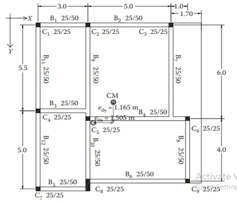
Discuss the suitability for earthquake resistance of the moment resisting framing plan of a three-storey building depicted here (cross-sectional dimensions in cm), the eccentricity of the centre of mass (as centroid of floor plan) to the centre of stiffness (from the moments of inertia of the columns) are shown. Suggest an alternative. Also, is there torsional flexibility? Are the two fundamental translational modes of vibration larger than the fundamental torsional mode of vibration. Discuss qualitatively.
Answer:
In this structural frame , there is a two-way eccentricity of the center of mass in accordance with the center of stiffness , which is eccentricity of x-direction is larger than y-direction.
In this structure beams are provided at stronger than column, so it can consider as Weak column strong beam design in nature.
Therefore this structure need some shear wall to resist the column failure, when the lateral forces acting about the structure.
Combination of shear wall and column tends to prevent the failure about the structure during the seismic forces occur.
As the frame plan, we can see about the alignment of beam is uniformly continuous of B1 and B2 at X- direction, and B11 & B12, B9 & B10 at Y-direction.
But another all beams are provided at discontinuous of structural frame, so here cause to difficult of transmission of load evenly at entire structure due to action of lateral forces.
Beams with long span may have their top reinforcement at the supports governed by factored gravity load, rather than by the seismic design situations.
Therefore,this structure will alternate to better portal of better offset at symmetric in nature.
The column beams connections should be in proper cross section area, then it achieve lateral stiffness, mass regularity, moment resisting factor.
As we consider beam-sway mechanism in strong column/ weak beam design frames is better, because of its achieve a uniformly spread, global inelastic displacement demand at roof level, to all storeys.
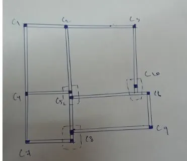
For here, we changed the column of C5 & C8 to considered as a combined footing, because of their need to avoid the loss of center of stiffness due to occur lateral forces about the structure.
And more we add one more column of C10 is covered that boundary of plan, should maintain the center of mass as well as the center of stiffness about the structure during ateral horizontal force action.
Any single plane frame should run continuously from one side of the building plan to the other, without offsets, interruptions (missing beams between adjecent columns in a floor), or indirect supports of beams on other beams.
If a beam does not continue straight from span to span, but its axis is offset at the column between them, there is no smooth flow of beam internal forces througn a proper beam-column joint, neither continuity of the beam longitudinal bars across the column from one span to the next: these bars have to terminate there and be separately anchored at the joint.
Even when the beam axis is not offset from span to span, the smooth flow of internal forces from the beams to the column is impaired by a large eccentricity between the axis of the beam and the supporting column.
If a beam terminates at an (indirect) support on another beam, there is large uncertainity concerning its rotational restraint by the supporting beam via torsion in the latter. In approximation, an indirect support may be considered as a simple support; the indirectly supported beam is less effective in frame action than one connected to columns at both ends.
Beams with long span may have their top reinforcement at the supports governed by factored gravity loads, rather than by the 'seismic design situation'.
This will result in beam overstrength, relative to the moment demand in the 'seismic design situation'.
The overstrength is carried over to the capacity design shears of beams and columns, penalizing them and creating some uncertainity whether plastic hinges will form in the beams or the columns. There is possibility of plastic hinge occuring away from face of column.
Beams with low span-to-depth ratio (less than 4) have to be dimensioned for high shear forces, from the seismic analysis or from capacity design in shear. Unless diagonally reinforced, short beams have low deformation capacity and poor ductility.
For the reasons detailed above, short beam spans should be avoided, while spans of 4 to 6m should be preferred over longer ones, at least for the storey heights and gravity loads commonly encountered in buildings.
Question 3:
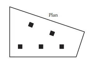
A multi-storey building with basement, with a quadrilateral (non symmetrical floor plan) plan as, has interior columns in an irregular (not in a grid) pattern in plan that serves architectural and functional considerations. Partition walls and interior beams supporting the slab have different layout in different stories. However, there is no constraint to the type, location and size of the lateral force resisting components and sub-systems on the perimeter. Proposals are to be made and justified for the choice of the lateral-load-resisting system and its foundation.
Answer:
This plan totally unsuitable for heavy seismic zone areas.
In this plan, the interior columns are in unsymmetric.
The partition wall are provided through the base of beam, should support the lateral deformation due to the structure.
The interiors beams will supports the slab, then the lateral load resisting the failure due to earthquakes.
For this irregular columns in plan, there we provided the flat slabs, because its directly stay in a column centroidal axis.
For here, the beams at different locations is irregular in plan and are continuous and is disallowed to resist the seismic load in the region.
In this plan, the flat sab is more appropriate than a regular beam column junctions, because of as its provide support to the columns without any provision of the beam, which reduces the weight of the building and also helps in the ductility of the structure by indirectly.
for the solution of this structure, we provide the shear wall from the foundation of structure through vertical components, it should minimize the loss of sudden failure occur due to lateral force acting on structure.
The general layout and certain details of the geometry (shape, size and typology) of an individual plane frame have a major impact on its seismic behaviour. Very important also is the overall layout of the frames in a structural system.
The location of frames in plan and their span lengths are normally governed by architectural and functional considerations, while beam depths may be controlled by design for factored gravity/seismic loads.
Nevertheless, the structural designer is essentially free to choose the all important geometric details of individual plane frames and has certain freedom concerning their overall geometry and location in plan.
Frames place few constraints on a building's architectural design, including the facade and parking space in ground floor.
Frames may be cost-effective for earthquake resistance, because beams and columns are placed anyway for gravity loads; so, they may also provide earthquake resistance in both directions, if their columns are large.
Frames with concentric connections and regular geometry have well-known and understood seismic performance.
It is easier to design an earthquake-resistant foundation element for a smaller vertical member than for a larger one.
Frames are inherently flexible; the cross-section of their members may be governed by the inter-storey drift limitations under the moderate earthquake for which limitation of damage to structural and non-structural elements is desired.
Column counter-flexiure in the same storey allows soft storey mechanisms, which lead to collapse.
Earthquake-resistance requirements on frames lead to large columns, interfering with architectural functions.
The reinforcement detailing of frames for ductility requires workmanship of high level for its execution and good supervision on site.
The walls and frame systems each have their advantages and disadvantages as lateral load resisting systems.
Walls seem to have a better balance of advantages against drawbacks; nevertheless, a concrete building always has beams and columns to support the gravity loads; it is a waste not to use them for earthquake resistance.
Therefore frames and walls may well be cost-effectively combined in a single lateral-load-resisting system.