Concept on positioning of Columns
Question 1:
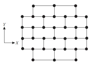
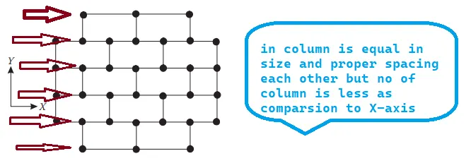
Comment on the layout of the framing plan concerning earthquake resistance in the two horizontal directions X or Y (dots are columns, lines depict beams). Look into aspects of symmetry, redundancy and bi-directional stiffness and ductility.
Answer:
1. Symmetry:
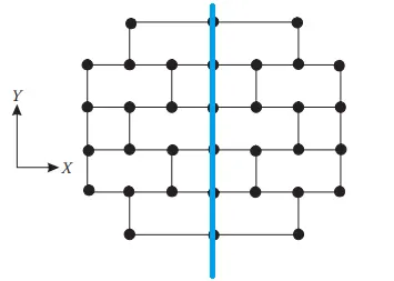
- The layout is generally symmetrical in both X and Y directions, meaning the centre of mass and centre of rigidity are likely to be close.
- Symmetry is highly favorable for earthquake resistance because it minimizes torsional irregularities (uneven twisting during seismic motion).
2. Redundancy:
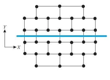
- The frame has multiple load paths due to the dense grid of columns and beams.
- This redundancy improves performance during an earthquake because if one member fails, loads can be redistributed through alternate paths.
- High redundancy enhances the structural robustness and resilience.
3. Bi-Directional Stiffness & Ductility:
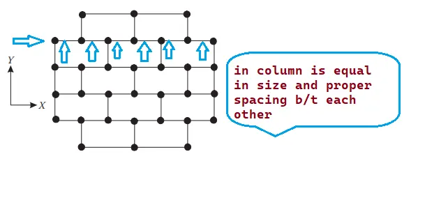
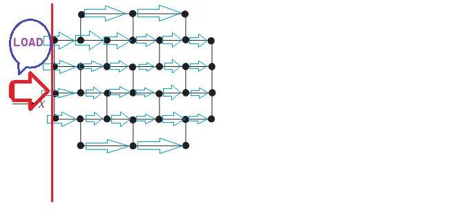
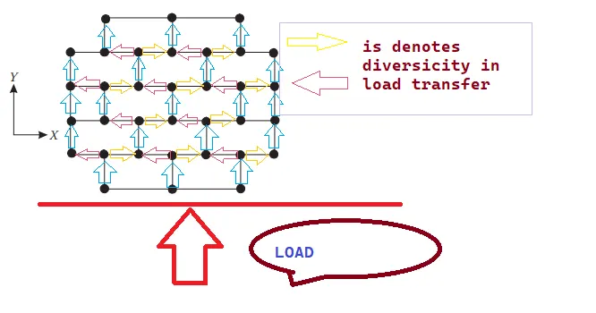
- The stiffness appears fairly uniform in both X and Y directions because:
- Beams and columns are consistently spaced.
- There are nearly equal numbers of frames in both directions.
- This bi-directional stiffness ensures the structure can resist seismic forces from any horizontal direction.
- The use of moment-resisting frames (as implied by the connectivity) offers good ductility, essential for energy dissipation during an earthquake.
Potential Concerns:
- If beam or column sizes vary (not shown in the schematic), stiffness might be unbalanced in one direction.
- The openings (if any exist for doors/windows in reality) or non-uniform column heights could lead to weak/soft-storey mechanisms – this needs verification with architectural plans.
Conclusion:
The framing layout demonstrates good earthquake-resistant characteristics:
- Symmetrical in plan → minimal torsion
- Redundant system → multiple load paths
- Balanced stiffness in X and Y → equal seismic performance
- Likely ductile detailing → suitable for seismic zones
Question 2:
What are the possible sources of irregularity in the building shown here? Explain how, as an engineer, each of these irregularities should be dealt with.

Answer:
Aim
To identify and analyze possible structural irregularities in the given building and propose appropriate engineering solutions to enhance its earthquake resistance.
Introduction
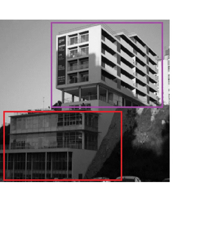
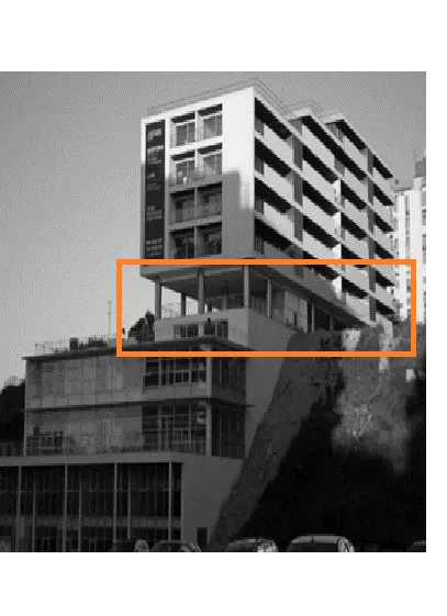
Buildings located in seismically active regions must be designed with consideration for structural irregularities. Irregularities can lead to stress concentrations, unbalanced load distribution, and structural failure during an earthquake. The image shows a multistorey building with varying floor levels, geometries, and column arrangements, all of which may result in significant seismic vulnerabilities if not addressed properly.
Procedure for Assessment and Rectification
1. Visual Assessment
Analyze the image for signs of irregularities using seismic design principles and IS 1893 code provisions.
2. Identification of Irregularities
The following are the main observed irregularities:
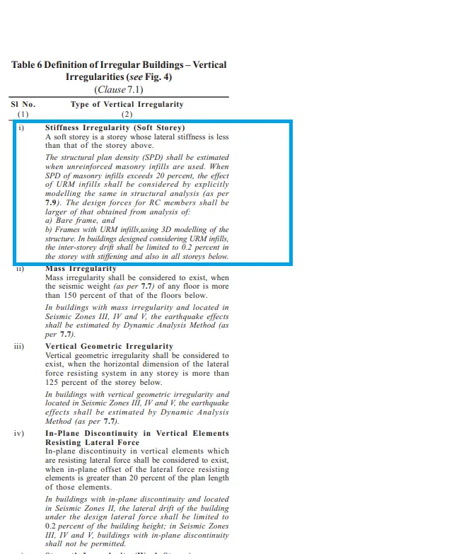
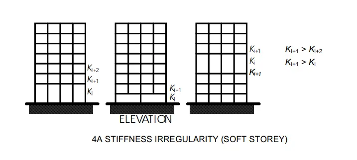
Vertical (Soft Storey) Irregularity:
- Observation: The upper massing is supported by slender, widely spaced columns at the podium.
- Impact: Reduced lateral stiffness and strength at the base — highly vulnerable during earthquakes.
Solution:
- Introduce shear walls, bracings, or closely spaced RC columns at the soft storey level.
- Design soft storey to handle larger drift demands using ductile detailing.
Mass Irregularity:
- Observation: A sudden increase in mass (residential tower) above lighter floors.
- Impact: High seismic inertia loads transferred to lower stories.
Solution:
- Minimize mass variation between floors.
- Use base isolation techniques or design lower stories for increased lateral load capacity.
Plan Irregularity / Overhangs:
- Observation: The upper structure cantilevers significantly beyond the footprint of lower floors.
- Impact: Torsional irregularities and localized moments at support locations.
Solution:
- Minimize cantilevers, or reinforce support zones with additional columns or deep beams.
- Introduce torsional resistance through a balanced layout of structural walls or frames.
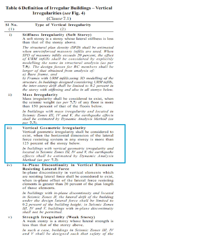
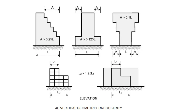
Vertical Geometric Irregularity:
- Observation: Abrupt change in geometry at podium and tower interface.
- Impact: Disruption in load paths and weak transition points.
Solution:
- Ensure continuous vertical load paths.
- Provide diaphragms or transfer girders to distribute loads smoothly between differing geometries.
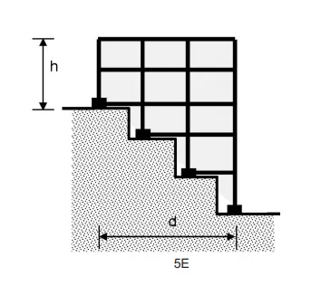
Foundation on Slope:
- Observation: The structure is partly supported on a steep slope.
- Impact: Uneven settlement, soil failure, or sliding during earthquakes.
Solution:
- Conduct detailed geotechnical investigation.
- Use retaining walls, deep pile foundations, and slope stabilization techniques (e.g., soil nailing, geogrids).
Conclusion
The building presents several structural irregularities that could adversely affect its seismic performance. As an engineer, it is critical to:
- Identify these irregularities during design and retrofitting stages.
- Use code-compliant detailing, material selection, and seismic load analysis.
- Ensure that irregularities are treated with appropriate ductility, redundancy, and load path continuity.
RESULT:
Question 3:
A 4-storey hotel building has an open ground floor for the restaurant. Story 2 to 4 have one row of rooms along each long side in plan, separated by a corridor. The two short sides of the perimeter are fully in-filled in all storeys, except for certain openings at the ends of the corridor at storeys 2 to 4 and along the right-hand side of the ground floor. There is a staircase near the upper left-hand corner, with straight flights between landings at floor levels and in-between floors. Cross-section dimensions are written next to the member no. in meters.
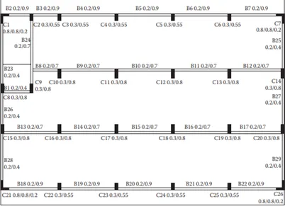
Comment on the features of the structural design and of the layout of infills which are important for earthquake resistance and seismic performance. How do they relate to the almost full collapse of this building (the extreme left-hand bay with the staircase survived, as well as one long-side façade in the rear end, and the frame along the right-hand side in plan).

Answer:
Aim:
To evaluate the features in the structural design and layout of infill walls of a 4-storey hotel building and their implications on seismic performance, explaining the partial survival and near-total collapse observed after an earthquake.
Introduction:
In earthquake-prone zones, the layout of structural and non-structural elements—especially infill walls, column-beam framing, and staircase cores—greatly influences the performance of buildings. The specific building in question has an open ground floor (soft storey), in-filled upper stories, and asymmetric infill distribution. These factors need to be assessed to understand the collapse pattern and survival of isolated portions.
- Open Ground Floor (Soft Story)
- Rooms along two bays separated by an open corridor (mass irregularity)
- Two short sides covered with infill walls (Stiffness irregularity)
- Staircase position at left top corner
- No framing connection along Y-direction (diversity in transferring load)
- Beams connected along column minor axes (ductility irregularity along Y-axis is less)
- Variations in column sizes
1. Open Ground Floor (Soft Storey)
Explanation:
An open ground floor refers to a building configuration where the ground level has significantly fewer walls, infills, or structural elements compared to the upper floors—often to allow for open space like a lobby, restaurant, or parking. This leads to "soft storey" behavior, where the lateral stiffness of the ground floor is much lower than that of the storeys above.
Why It’s a Problem (Seismic Viewpoint):
-
During an earthquake, the soft storey undergoes larger lateral displacements than the upper floors.
-
The stiffness discontinuity causes stress concentration at the first-floor columns.
-
This often leads to plastic hinging, column failure, or even pancake-type collapse of the ground floor.
Real-life Cases:
Several building failures in past earthquakes (e.g., Bhuj, Gujarat 2001; Nepal 2015) were due to soft storey collapse.
Solutions as an Engineer:
-
Avoid open ground storey designs in seismic zones.
-
If unavoidable, provide shear walls, braced frames, or moment-resisting frames at the ground level.
-
Use pushover analysis or nonlinear dynamic analysis to assess performance and retrofit accordingly.
2. Rooms Along Two Bays Separated by an Open Corridor (Mass Irregularity)
Explanation:
Mass irregularity occurs when there is a significant variation in mass (i.e., dead load and live load) between adjacent floors or within parts of the same floor. In the given case, the rooms are located along the two outer bays, while the central corridor is open, meaning that the mass is concentrated along the building’s edges, and the center is relatively light.
Why It’s a Problem (Seismic Viewpoint):
-
Uneven mass distribution leads to unequal inertial forces during an earthquake.
-
The building’s center of mass and center of stiffness do not coincide, causing torsional effects (twisting motion).
-
This twisting can severely damage columns, walls, and beams near the corners or edges.
Resulting Risk:
The building becomes vulnerable to torsional vibrations, which are often more damaging than translational (side-to-side) shaking.
Engineering Solutions:
-
Try to achieve uniform mass distribution by balancing the layout or adding mass to the lighter zone.
-
Add lateral load resisting elements (LLREs) like shear walls near the core.
-
Use torsional-resistant framing systems or design using 3D dynamic analysis to account for torsion.
3. Two Short Sides Covered with Infill Walls (Stiffness Irregularity)
Explanation:
Stiffness irregularity arises when some parts of a building are significantly stiffer (resist deformation) than others. In the given building, only the two short sides have full infill walls, while the long sides are largely open. This leads to a high stiffness concentration on just two faces of the structure.
Why It’s a Problem (Seismic Viewpoint):
-
During an earthquake, stiffer parts of the building attract more seismic force, while flexible areas undergo larger displacements.
-
This uneven lateral stiffness distribution causes stress concentrations and uneven load transfer, especially at junctions between stiff and flexible zones.
-
It can result in shear cracks, failure of beam-column joints, or pounding effects between stiff and flexible sections.
Consequences:
-
Reduced overall seismic performance.
-
Potential for asymmetric drift, leading to twisting and localized collapse.
-
Damage to the infilled walls (brittle failure) or surrounding frame.
Engineering Solutions:
-
Ensure uniform distribution of infill walls or provide structural bracing/shear walls on all sides.
-
Consider moment-resisting frames or dual systems that combine frames and shear walls.
-
Perform dynamic analysis to assess how stiffness affects response and design accordingly.
4. Staircase Position at Left Top Corner
Explanation:
In the given building, the staircase is located at the top left corner, which creates an eccentric (asymmetrical) stiffness and mass distribution in the building plan.
Why It’s a Problem (Seismic Perspective):
-
Eccentric Mass and Stiffness: Staircases, especially if enclosed with shear walls or masonry, act as stiff elements. Placing them asymmetrically (in the corner) causes an uneven distribution of stiffness and mass, which leads to torsional (twisting) behavior of the building during an earthquake.
-
Torsional Irregularity: When earthquake forces act, the building tends to rotate about its center of mass, leading to higher stresses and drifts in certain columns or frames. This can cause premature failures in those structural elements.
-
Lack of Redundancy: If the stair core is damaged or isolated, evacuation routes and vertical stability may be compromised.
Consequences:
-
Excessive torsion and unequal displacement in floors.
-
Concentration of damage near the staircase or diagonally opposite corners.
-
Reduced safety of evacuation paths.
Engineering Solutions:
-
Centralize the stair core or distribute stairwells symmetrically to avoid torsion.
-
If unavoidable, provide additional lateral load-resisting elements (like shear walls or bracings) in opposite corners to balance stiffness.
-
Carry out torsional analysis and design structural elements to accommodate expected rotational displacements.
5. No Framing Connection Along Y-Direction (Diversity in Transferring Load)
Explanation:
In the given building, the structural framing appears to be discontinuous or insufficient along the Y-direction (shorter direction in plan), meaning that there are fewer or no continuous beams or columns connecting frames in that direction.
Why It’s a Problem (Seismic Perspective):
-
Weak Direction: Without a proper load path in the Y-direction, the structure lacks lateral stiffness and strength to resist seismic forces from that direction.
-
Unbalanced Load Distribution: Earthquake forces act in all horizontal directions. If framing is missing in one direction, loads cannot be effectively transferred to the ground, leading to concentration of stress in other elements.
-
Higher Displacement: Insufficient connections result in greater lateral drift, increasing the risk of non-structural damage and instability.
-
Out-of-Plane Failure Risk: If infill walls or façade elements are present without proper support, they may collapse out-of-plane due to lack of lateral restraint.
Consequences:
-
Potential for partial or full structural collapse under seismic loading in Y-direction.
-
Pounding effects with adjacent structures if displacement is excessive.
-
Increased vulnerability at beam-column joints, particularly at discontinuities.
Engineering Solutions:
-
Ensure continuous moment-resisting frames or shear walls are provided in both X and Y directions.
-
Add braced frames or structural walls strategically to restore bidirectional stiffness.
-
Conduct a 3D structural analysis to verify that lateral load resistance is adequate in all directions.
-
Improve connectivity between structural members to ensure reliable force transfer.
6. Beams Connected Along Column Minor Axes (Ductility Irregularity Along Y-Axis Is Less)
Explanation:
Columns are designed with stronger (major) and weaker (minor) axes, based on their cross-sectional orientation (e.g., rectangular or I-shaped columns). If beams are predominantly connected along the minor axis of columns (narrower face), the structural system becomes less effective in resisting lateral loads in that direction (here, the Y-axis).
Why It’s a Problem (Seismic Context):
-
Lower Bending Resistance: The column’s minor axis has a smaller moment of inertia, offering less resistance to bending and shear forces.
-
Reduced Ductility: Ductility is a structure’s ability to deform without failure. A system relying on the minor axis for load transfer may fail early during seismic events due to less energy dissipation capacity.
-
Torsional Effects: Irregularity in stiffness and strength across axes can cause the building to twist or rotate, increasing the complexity and risk of failure.
Consequences:
-
Early yielding of columns along Y-direction during earthquakes.
-
Increased inter-storey drift in the Y-axis, leading to damage in non-structural components.
-
Potential for soft-storey formation if the minor axis is overstressed and fails.
Engineering Solutions:
-
Orient columns properly so that beams align with their strong axes in both X and Y directions.
-
Use symmetric cross-sections (e.g., square columns) if space and design allow, for equal strength in both directions.
-
Provide lateral bracing or shear walls to support weaker axes and balance stiffness.
-
Ensure seismic detailing at joints to improve ductile performance.
7. Variations in Column Sizes
Explanation:
When a building has inconsistent column sizes (different cross-sectional dimensions or reinforcement details) across storeys or within the same storey, it leads to irregular load paths, uneven stiffness, and unpredictable seismic behavior.
Why It’s a Problem (Seismic Context):
-
Weak Storey Formation: Smaller columns may yield or fail earlier under lateral seismic forces, especially if placed under larger, stiffer columns above.
-
Stiffness Irregularity: Unequal column sizes result in non-uniform stiffness distribution, making some parts of the structure take more force than others.
-
Load Path Disruption: Earthquake loads might not transfer efficiently from superstructure to foundation if column sizes change abruptly, leading to local failures.
-
Construction Complexity: It increases execution difficulty, poor quality control, and potential errors in reinforcement detailing.
Consequences:
-
Increased risk of progressive collapse due to failure in weaker columns.
-
Non-uniform deformation of the building during earthquakes.
-
Stress concentration in connections and slabs near transition points.
Engineering Solutions:
-
Maintain uniform column sizes vertically and laterally, especially in seismic zones.
-
If unavoidable, ensure gradual transitions in size with proper detailing and checks.
-
Use advanced structural analysis to model force distribution and check performance.
-
Follow relevant IS Codes (e.g., IS 1893 & IS 13920) for seismic design provisions regarding irregularities.