Comparison of Bending in Beams
1. Objective:-
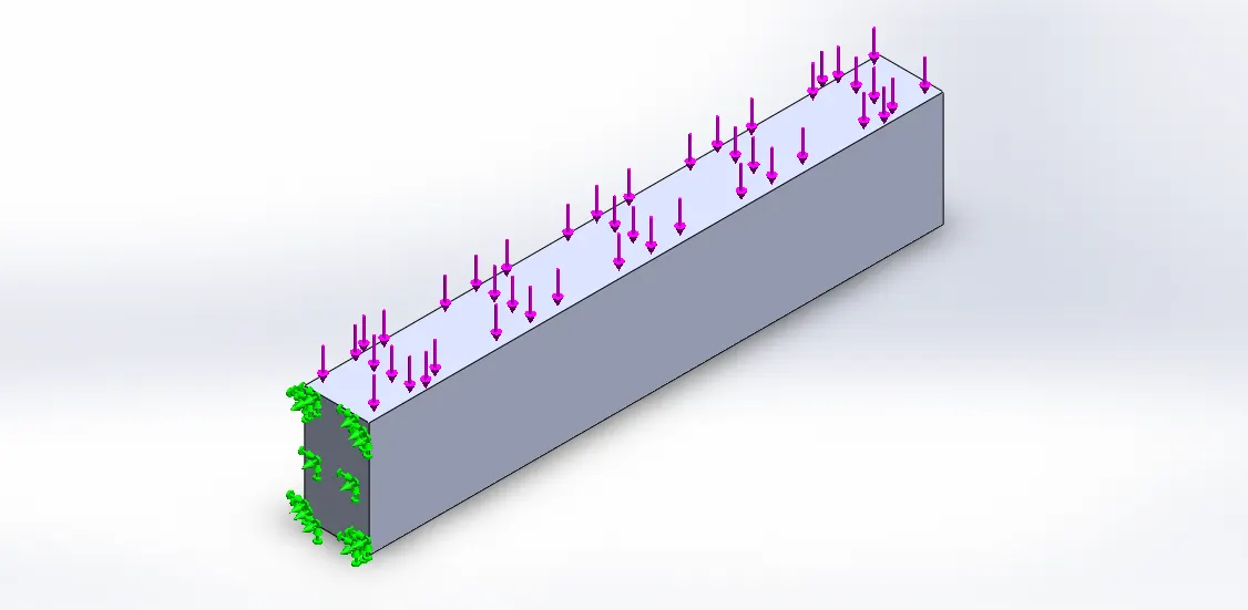
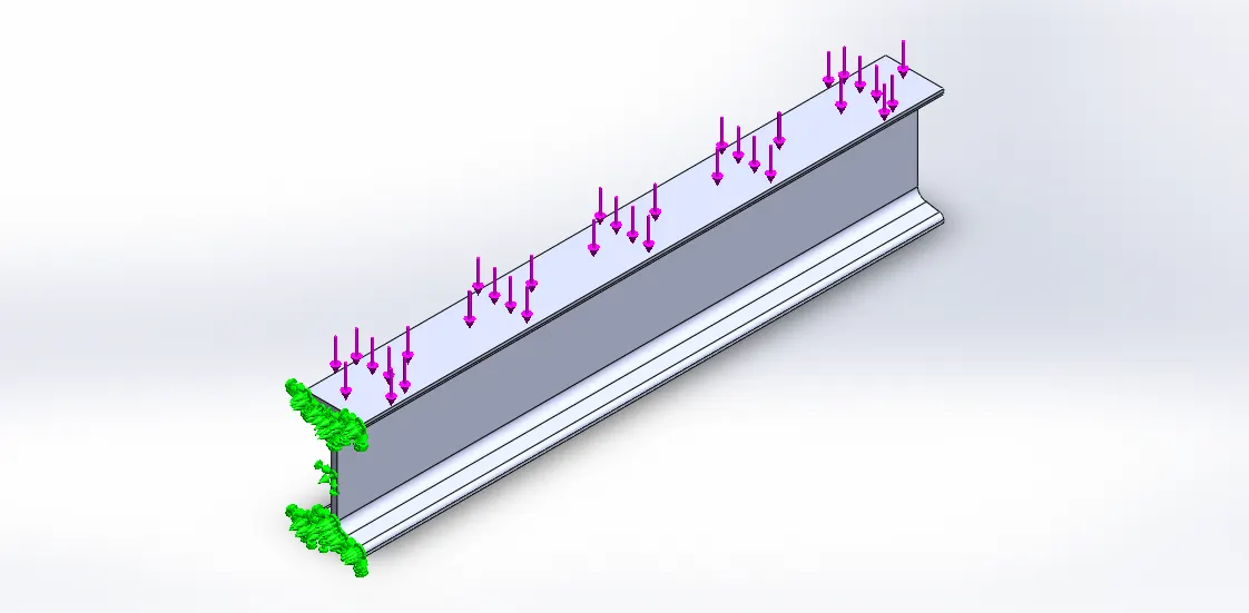
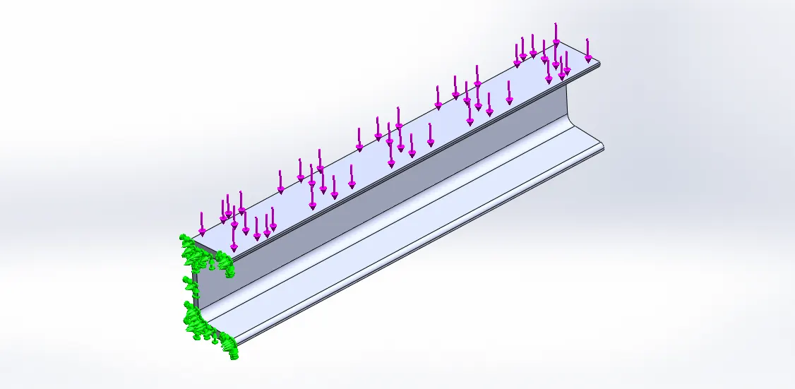
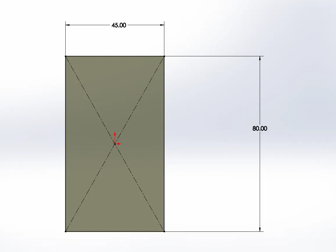
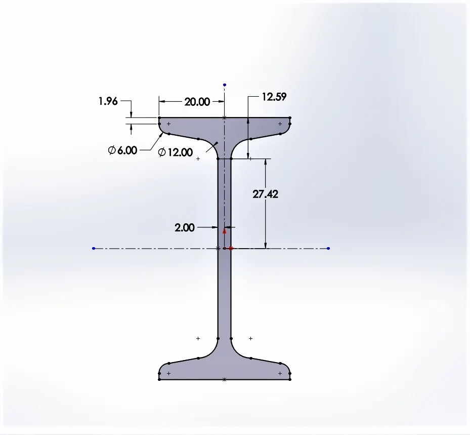
i. To create three types of the beam in Solidworks using the sketches shown below. (Extrude the sketches to a length of 400mm. Apply a load of 1500N on the smaller face (i.e. 45mm face for case 1, 40mm face for case 2 and 45 mm face for case 3).
ii. To compare the performance of three types of beams under a bending load such as the results of stress, displacement and strain for all the three cases and suggest the best out of the three.
2. Basics:-
2.1 Beams: A beam is a structural element that primarily resists loads applied laterally to the beam's axis. Its mode of deflection is primarily by bending. The loads applied to the beam result in reaction forces at the beam's support points. The total effect of all the forces acting on the beam is to produce shear forces and bending moments within the beam, that in turn induce internal stresses, strains and deflections of the beam. Beams are characterized by their manner of support, profile (shape of cross-section), equilibrium conditions, length, and material.
Beams are traditionally descriptions of a building or civil engineering structural elements, but any structures such as automotive automobile frames, aircraft components, machine frames, and other mechanical or structural systems contain beam structures that are designed to carry lateral loads are analyzed similarly.
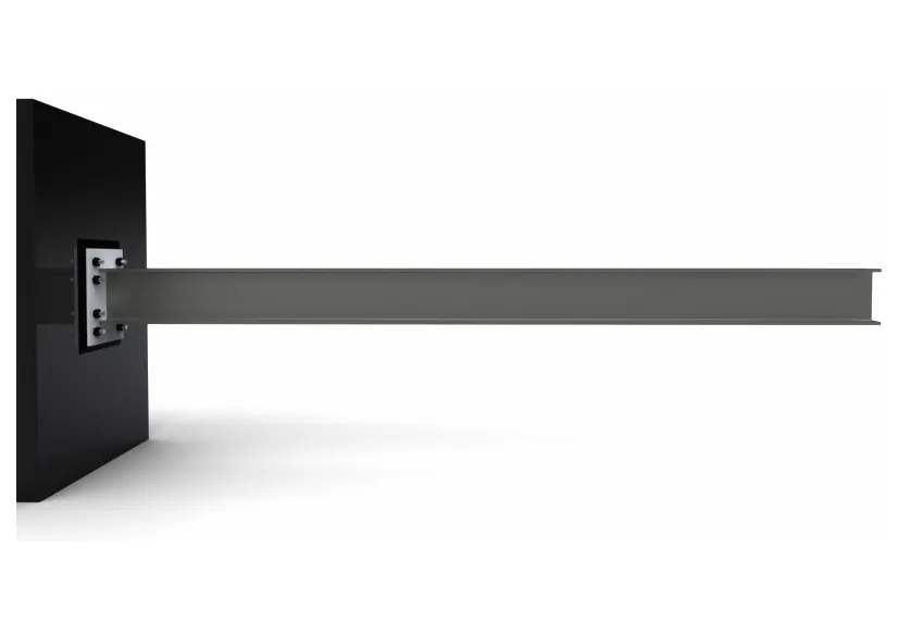
2.2 Cantilever Beam: In our Simulation, we are using the Cantilever beam of Different types.
If a beam is fixed at one end and set to be free at the other end, it is termed as a cantilever beam. The beam distributes the load back to the support where it is forced against a moment and shear stress. Cantilever beams allow the creation of a bay window, balconies, and some bridges.
2.3 Types of Cantilever Beam: There are many types of beams available but for our simulation, we need only cantilever beams of following types.
i. Rectangular Beam: It is also used to a great extent in the fabrication of enclosures, automobiles and many other structural applications if it is hollow but in our case, we are taken Rectangular Beam as solid to analyse the advantages of another beam over it.
ii. I-section Beam: Structural Beams are also known as I Beams or H Beams, and W Beams for the wider flanged versions. Some construction companies refer to them as Universal Beams or Rolled Steel Joists (RSJ). Typically they are used in the construction of buildings for structural support. The part of the Structural Beam that provides resistance to shear forces (breaking, tearing apart, or collapsing) is the web, while the flanges resist the bending movement of the section.
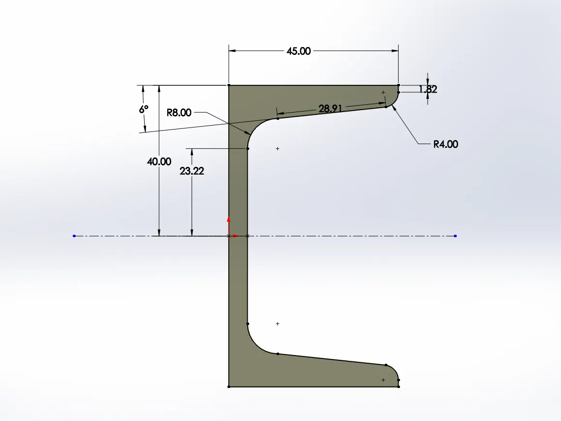
iii. C-shaped beam: When looking at a cross-section it has a vertical web with horizontal top and bottom flanges. It comes in a wide varying range of sizes and web thicknesses. The shape of this type of product provides a great amount of structural strength, making it an ideal product for making frames and bracing. Typically it is used in the manufacturing of machinery, enclosures and vehicles. It is also used in the construction of buildings for structural support.
3. Procedure:-
The Procedure for an analysis of the different types of Beams is as follows.
Step-1: Drawing Sketch of Rectangular, I-section and C-shaped beam in the Solidworks with the help of the sketch provided.
Step-2: Extruding all the sketch to a length of 400mm.
Step-3: Defining the New simulation for each beam as a static structural analysis.
Step-4: Fixing one end of the beam.
Step-5: Applying a load of 1500N on the smaller face of the beam i.e. 45mm face for Rectangular beam, 40mm face for I-section Beam and 45 mm face for C-shaped Beam as shown below.
Step-6: Defining fine Mesh to get better results.
Step-7: Run Simulation.
4. Simulation & Analysis:-
Material Used: default material (here material is not taken into consideration because our comparison is dependent on the different shape of the beam so we can choose any beam material such as aluminium alloy, Steel alloy (or) even plastic also.)
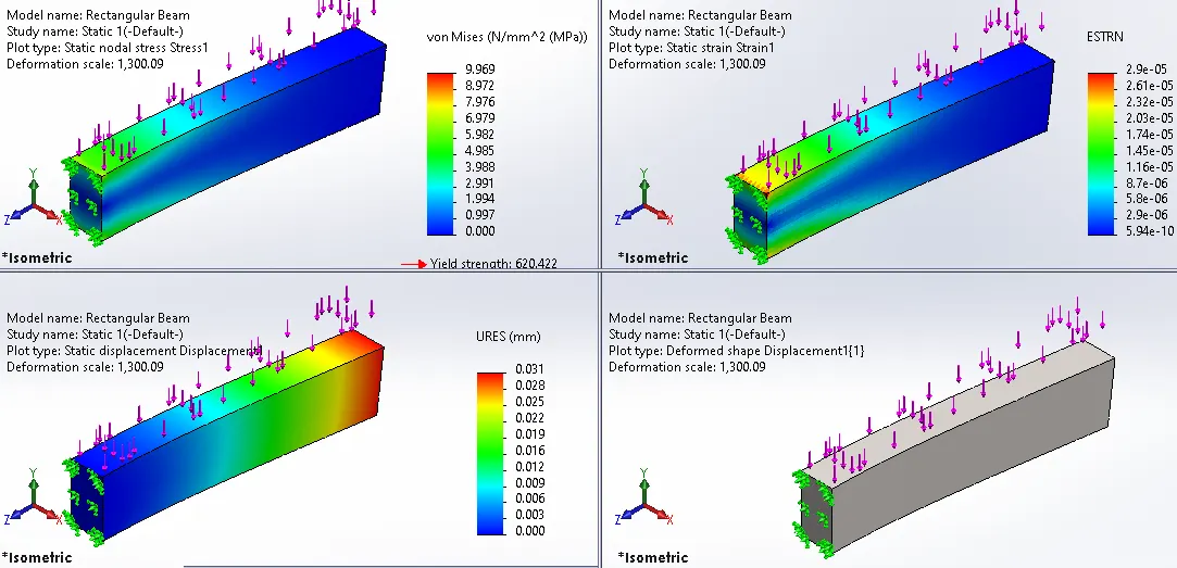
4.1 Rectangular Beam:-
i. 2D Sketch:
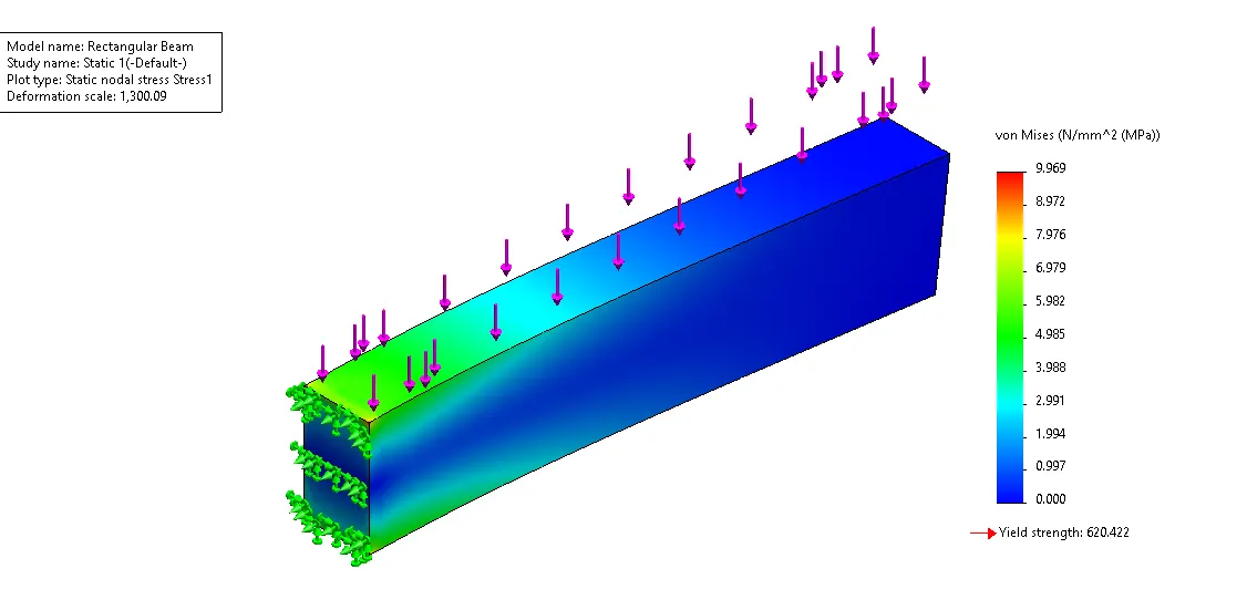
ii. Stress View:
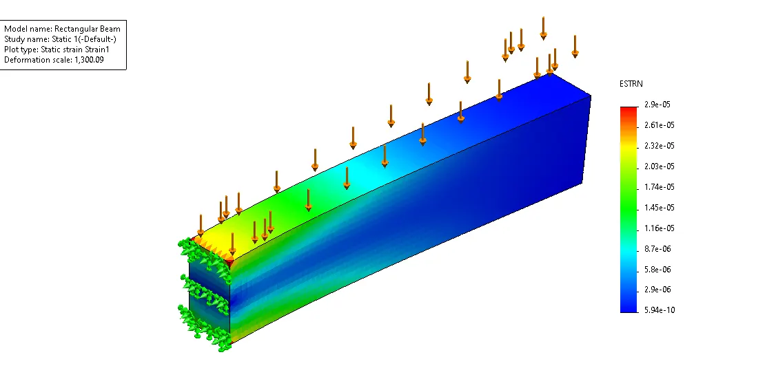
iii. Strain View:
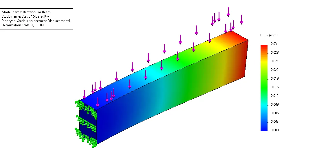
iv. Displacement View:
v. Combined View:
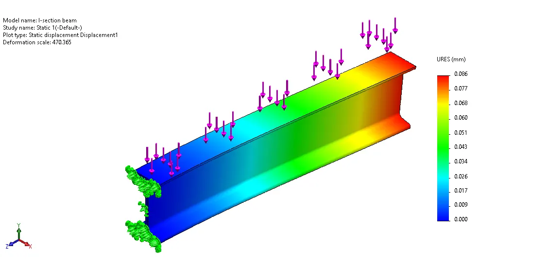
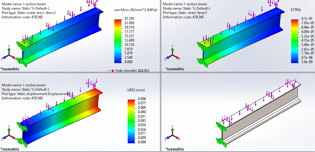
4.2 I-section Beam:
i. 2D Sketch:
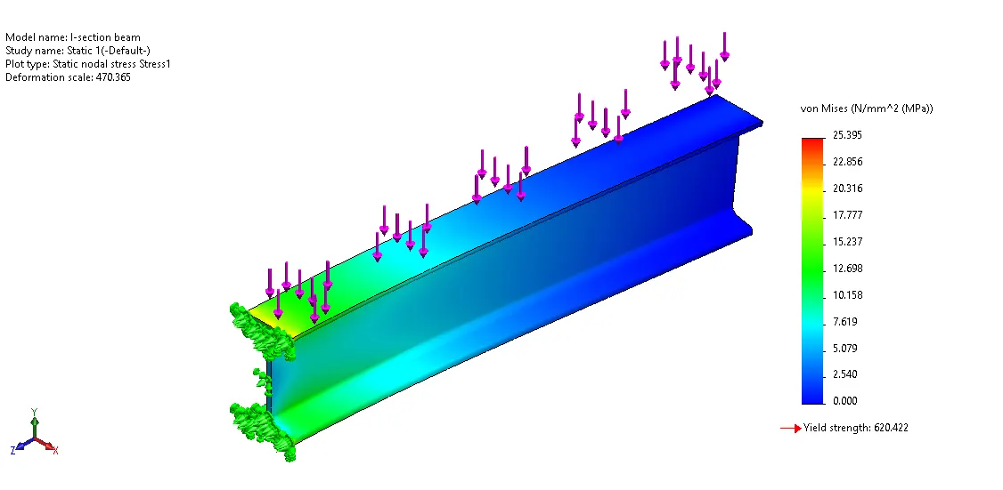
ii. Stress View:
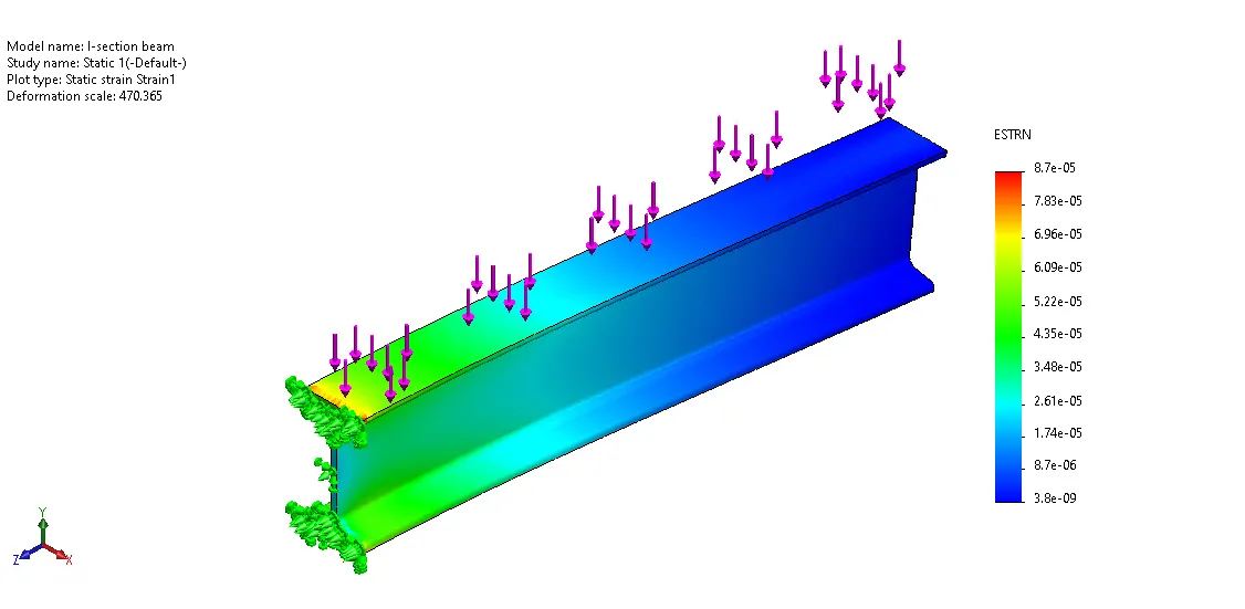
iii. Strain View:
iv. Displacement View:
v. Combined View:
4.3 C-shaped Beam:-
i. 2D Sketch:
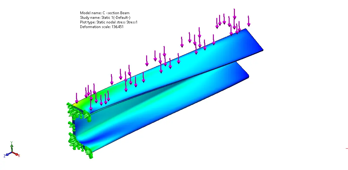
ii. Stress View:
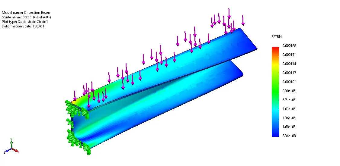
iii. Strain View:
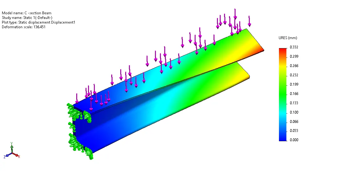
iv. Displacement View:
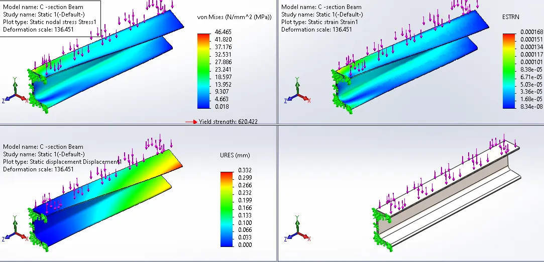
v. Combined View:
5. Result and Conclusion:-
Comparing Beams:
| Analysis Type | Rectangular Beam | I-Section Beam | C-Shaped Beam |
|
Max Stress (N/mm^2) |
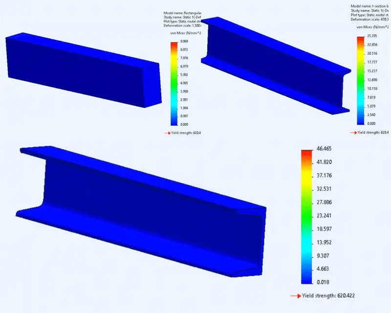
9.968 | 25.395 | 46.465 |
|
Max Strain |
2.9e-0.5 | 8.7e-05 | 0.000168 |
|
Max Displacement (mm) |
0.031 | 0.086 | 0.332 |
|
Min Factor of safety |
62 | 24 | 13 |
|
Mass (kg) |
11.08800 | 2.36712 | 3.12146 |
|
Volume (m^3) |
0.00144 | 0.00031 | 0.00041 |
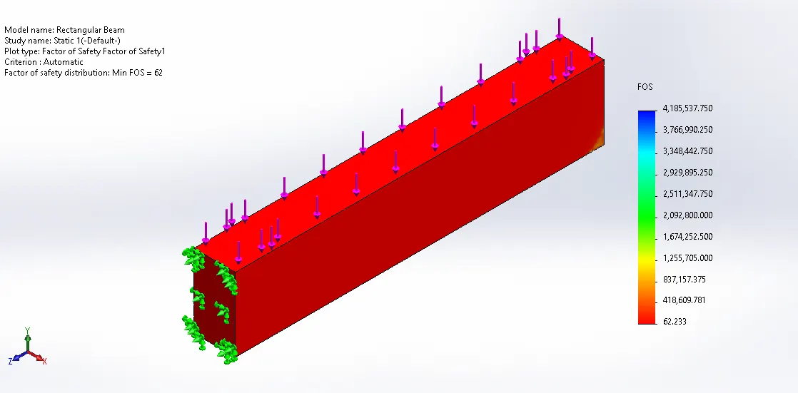
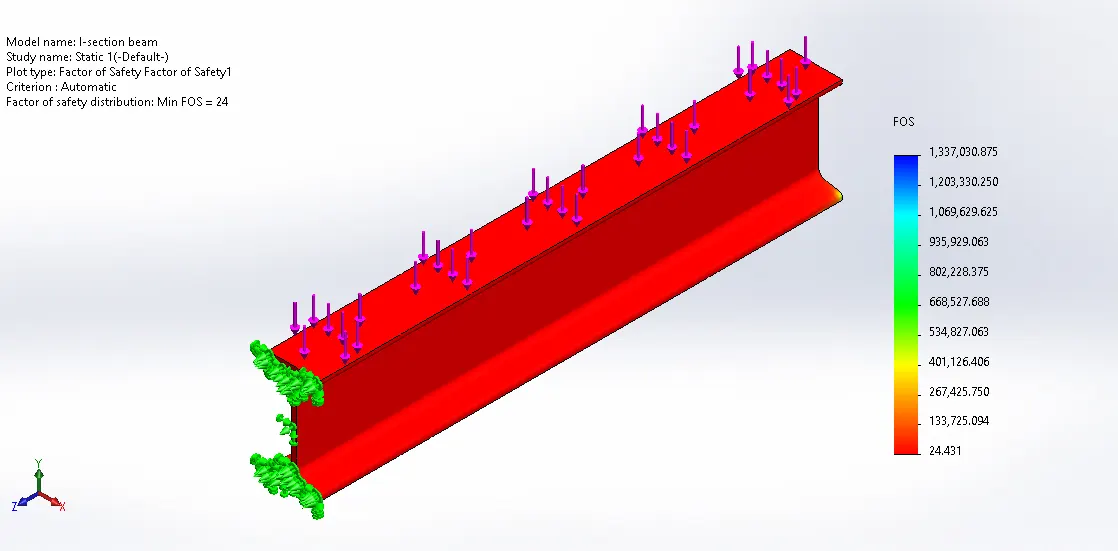
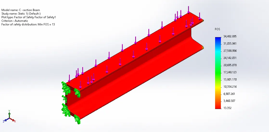
From All the Data of Table containing the stress, strain, Displacement and Factor of safety we can say that the I-section Beam have intermediate values between the Rectangular Beam and C-shaped Beam. the Observation related to the data is discussed as follows.
i. The Stress and stain are minimum in a rectangular beam, intermediate in the I section and high in C section because in a rectangular beam have more cross-sectional area and I section have comparatively a less cross-sectional area. we know that as Area increases, Stress decreases ( stress = normal force / cross-sectional area).
Also, stress and strain are related to each other. In case of C beam, the mass is higher as compared to I beam and the twisting is also occurred along with bending, that causes more stress and strain in this beam.
ii. The displacement is high at I section beam because in I section the less mass is away from neutral axis causes less MOI as compared to a rectangular beam. The Normal stress develops due to bending of a beam when force couple acts along the transverse direction and shear stress develops due to twisting of the beam when force couple acts along a longitudinal axis and it tries to rotate the beam around its axis. Therefore in the C beam, we can see both twisting and bending.
iii. In other terms, We can say that the Rectangular Beam Have maximum stress, strain, Displacement and Factor of safety, C-shaped Beam Have a minimum and the I-section Beam has an intermediate value of stress, strain, Displacement and Factor of safety. In Engineering Application, if we have a Factor of Safety from 2 to 3 is considerable. Though the I-section beam has less Factor of Safety than Rectangular Beam, it is considered as more economical. This is due to the I-section beam can handle the same load acting on the Rectangular beam with less use of material. hence it is economical in terms of cost and working condition.
iv. Also, as we know Flexural strength of beam depends upon moment of area of cross-section of the beam. This indicates that for the same cross-sectional area of beam moment of the area increases very much with the increase of depth and hence its flexural strength. But I- section beam is the most efficient shape only for one direction bending. If we turn that I beam 90degs (basically into an H beam), it would be less strong than a square beam. I beam will also be worse than the square tube (Hollow Beam) in torsional loading. So before picking I- section beam it is completely Depend on loading type.
v. The problem with I-section Beam is that we only have two parallel faces to mount. Mounting to a face parallel to the web means adding an angle to the flanges. C-section channel overcomes this by moving the web out to one edge of the flanges, changing the cross-section from an “I” to a “C” in the process. Also, we can make an I-section beam by combining two C-section Beams.
vi. C-section thus has three flat surfaces for mounting to. It’s still strong, although this geometry does give up a little of the rigidity of the I-beam. Against that though, it avoids the use of brackets or angle. That saves money, time and weight, perhaps making it worth moving up to a slightly heavier section.
Reference:-
https://www.metalsupermarkets.com/
https://www.wileymetal.com/why-you-might-consider-c-section-channel-for-a-metal-fabrication/
https://youtu.be/8Ob2tVP5miE
The Flow of Report:-
1. Objective.
2. Basics.
3. Procedure.
4. Simulation & Analysis.
5. Result and Conclusion.