CLEANUP THE GIVEN COMPONENTS AND EXTRACT THE MIDSURFACE FOR PLASTIC COMPONENT
AIM :
To Cleanup geometry of given components and extracting the midsurface if cross section thickness is below 6mm.
OBJECTIVE :
1) Cleanup the given components in manually for meshing .
2) Extracting the midsurface of a component if a thickness of cross section is below 6mm.
3) Cleanup the extracted midsurface for meshing.
CAD MODEL IMAGE :
Housing :
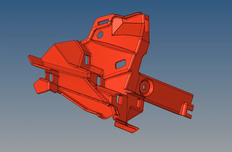
1) Open a hyperworks software, go to "Import geometry" option with select the file type which is "STEP", select the appropriate file and then import.
2) This is the CAD model after it importing into hyperworks, by default a "Auto Mode" had been enabled from where "Geometry color mode" option. If "Auto Mode" is enable, a component surface & color will always looks like extractly same as below snap Until a color has change in manually from where respective component under from which "Tab Area".
Plastic component :
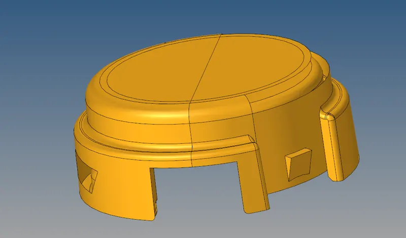
1) This is the another model it will perform separate file, open a hyperworks software go to " Import geometry" option with select the appropriate file type which is "STEP", select the respective file and then import.
2) Below snap is a CAD model, it will appearing into the graphical area after which import the file, by default " Geometry color mode" option has set to be "Auto mode". If "Auto mode" is selected, a component looks graphically same as below snap.
PRODURE FOR ATTAINING THE OBJECTIVES :
MODEL 1 :
Changing the Geometry color mode :
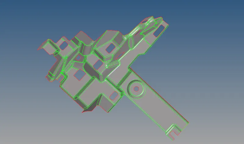
1) By default "Auto Mode" is enable in " Geometry Color Mode", if "Auto" Mode is enable couldn't see any "Free edges, sharped edges, T-Junction edge and Supressed edge" these are the important aspects for geometry cleanup.
2) Change into "By Topology" mode instead of "Auto" mode from "Geometry Color Mode". After changing into "By Topo", we have to view topology aspects on the component such as "Free edges, sharped edges, T-Junction edge and Supressed edge".
3) First snap is a "Auto mode", Second snap is a "By Topo" mode.
Finding the geometry errors :
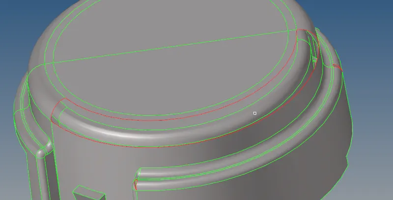
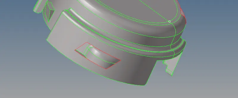
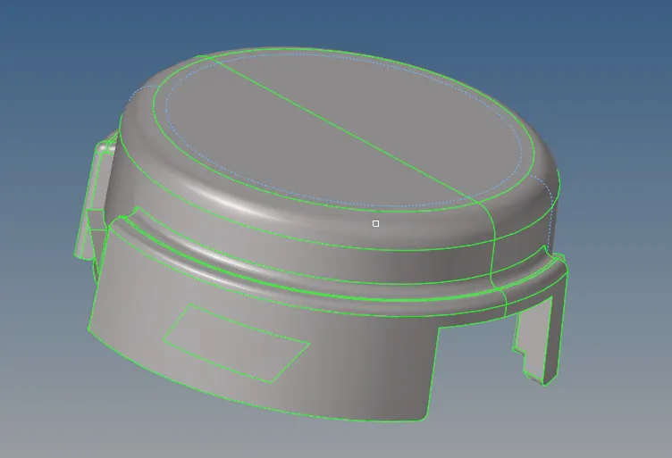
After converting into "By Topo" mode, we can easily view the geometry errors on a component. In this component, a fillet surface is missing and also some small surfaces are missing on a component. In below snap also some surface are missing in this component.
By resolving those issues, we have to use some useful option such as filler or spline and Ruled option to cleanup those errors.
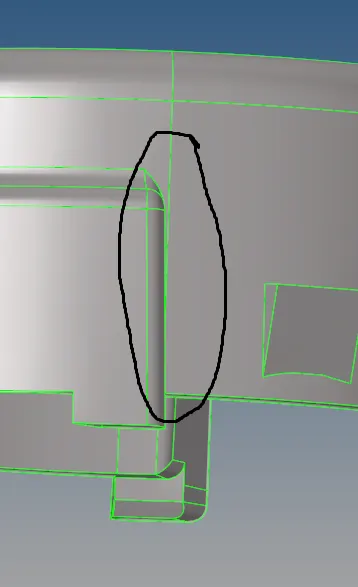
A Sharped edges are very close to each other at where place of annotate region in below snap. If it's happens when creating an mesh, it will affects the element quality.
Geometry Cleanup :
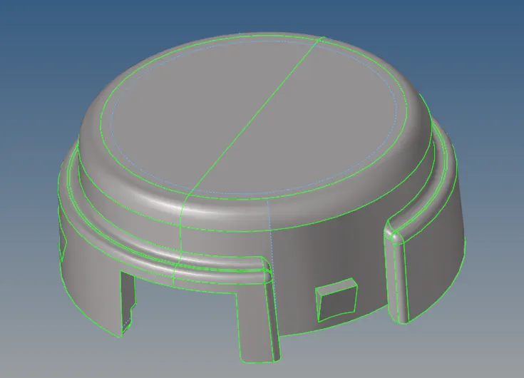
1) By using spline or filler option to create a fillet at where missing area and also some places a surface had missing, so by using filler option to fill the missing gaps.
2) In this case we shouldn't go to meshing, but we have to cleanup geometry for which creating an meshing. If the two line internal distance has been below 2mm, it will affects the element quality. So, we have to supressing manually by using "Toggle edge" option. After suppressing, it seems in blue color dotted line. Select the "toggle option" then right click on a mouse button, it will converts into suppressed edge.
3) Now this model is ready to meshing.
MODEL 2
Changing the Geometry color mode
1) By default "Auto Mode" is enable in " Geometry Color Mode", by enable "Auto" Mode option couldn't see any "Free edges, sharped edges, T-Junction edge and Supressed edge" these are the important aspects to cleanup the geometry.
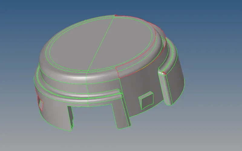
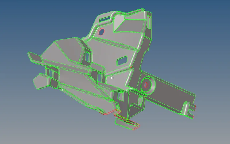
2) Change into "By Topology" mode instead of "Auto" mode from "Geometry Color Mode" GUI. After changing into "By Topo", we have to view topology aspects on the component such as "Free edges, sharped edges, T-Junction edge and Supressed edge".
3) First snap is a "Auto mode", Second snap is a "By Topo" mode.
Geometry Cleanup :
By viewing from "By topo" mode, it will shows us topology error or geometry error from that component. So, we need cleanup those error in manually.
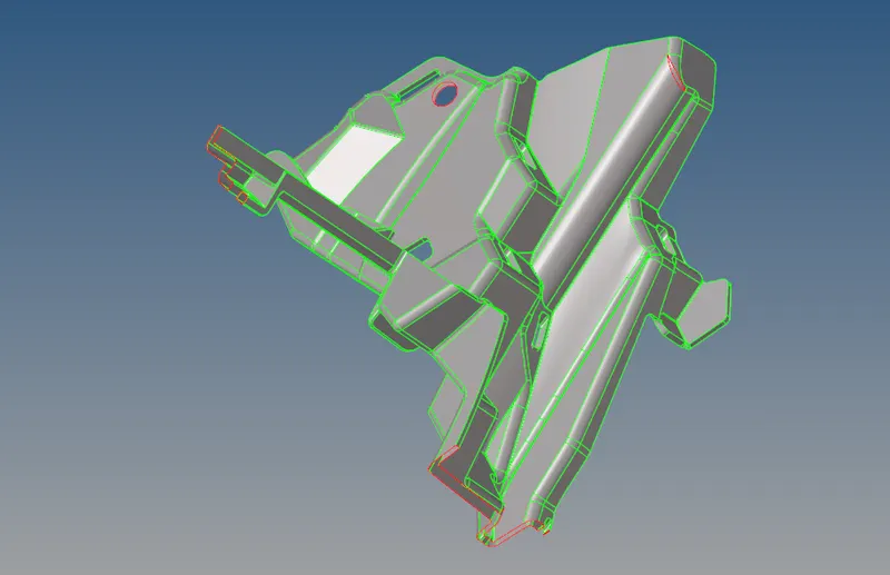
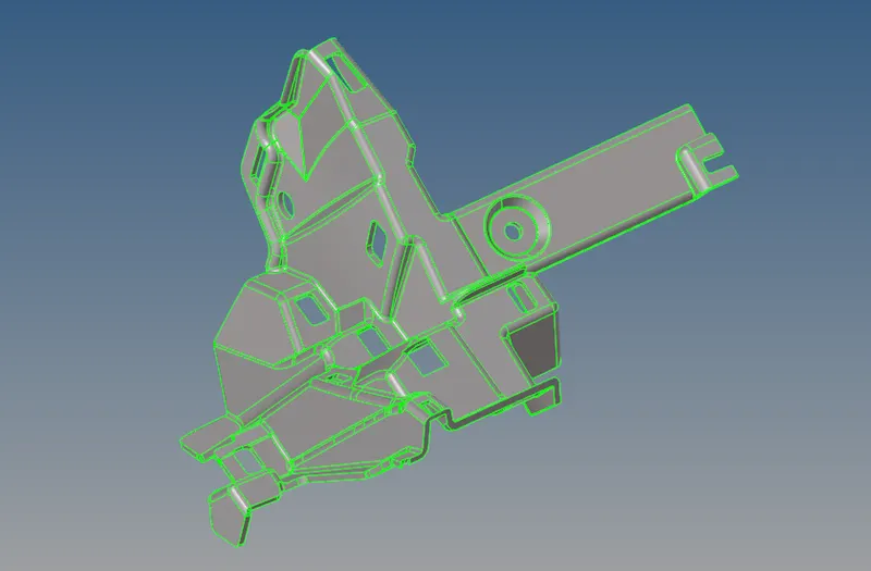
By using filler/spline or ruled options to cleanup the component without any geometry error like missing surfaces and some unclosed surfaces.
Creating a midsurface :
Generally, a midsurface creates between two surfaces, it helps to minimize the calculating time, storage space and gives better results. If the cross section of the component is same as throughout the model, we have perform by using "Auto Extraction" under "Auto Midsurface" option to which create a Midsurface. In this case cross section has seems same as throughout the component and also thickness satisfied below 6mm. For Extract the good midsurface, we have to perform different types of automatic extraction methods which are under "Extraction Options".
There is a types which are sort out below,
1) Offset + Planes + Sweeps
2) Offset + Planes
3) Offset
4) Skin Offset
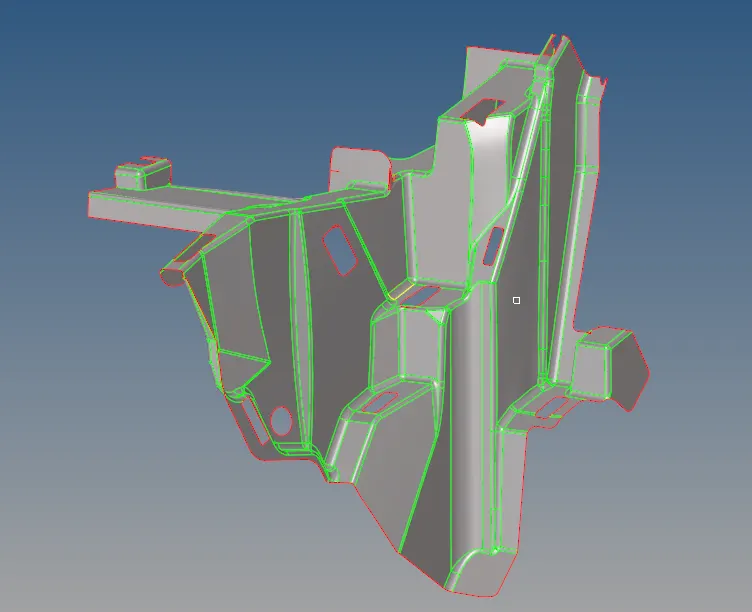
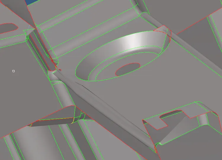
i) Offset + Planes + Sweeps :
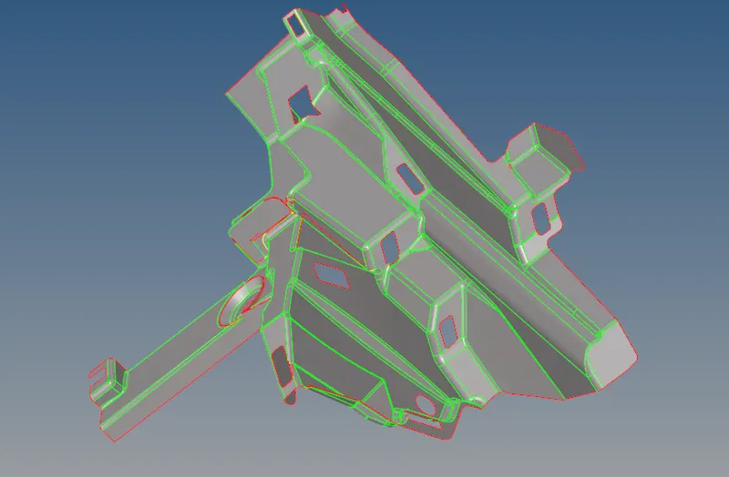
By using this method, actually a midsurface had created but it's couldn't creates properly. It misses some surface on a midsurface and also not possible to manually cleanup this geometry.
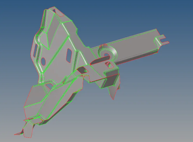
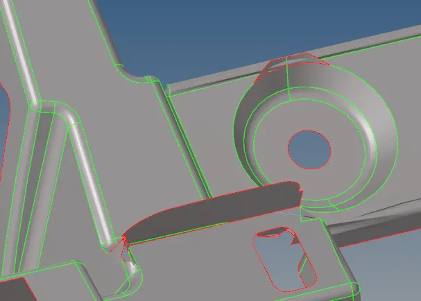
ii) Offset + Planes :
In this case also seems some missing surfaces on a midsurfaces. So, we need perform by using another extraction method.
iii) Offset :
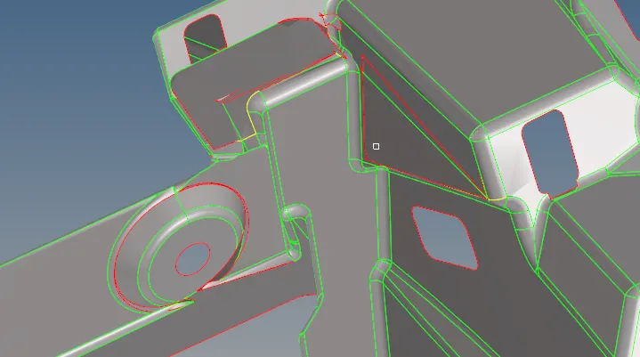
In this case also some more geometrical errors are seems on this midsurface. So, we need go to "Skin offset" method.
iv) Skin Offset :
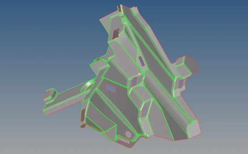
In this case almost gives us proper midsurface throughout the component except some few area, we need to cleanup the component in manually on those areas.
Geometry cleanup for Midsurface :
Before Geometry cleanup :
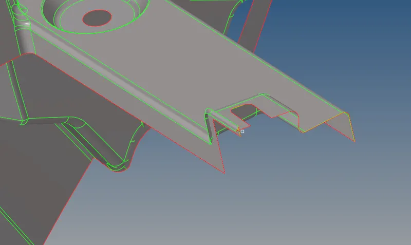
By using "Skin Offset" option to create a proper midsurface successfully, but we seems some geometrical errors on a surface. So, we have to perform manually cleanup those areas by using " Delete option, Trim with surfs option, filler option and Ruled option" in proper manner.
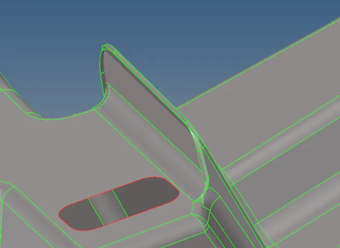
After Geometry Cleanup :
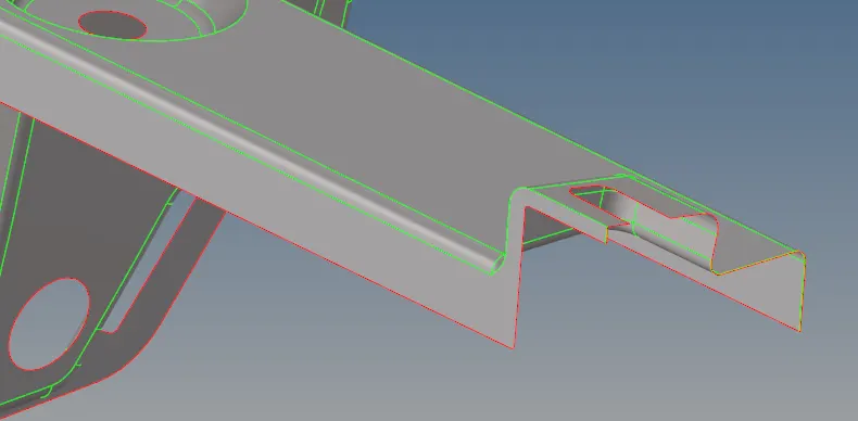
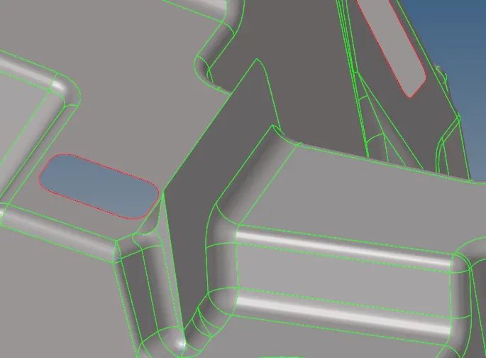
After completion of manual cleanup on those particular areas on extracted midsurface. Now it's looks proper flow thoughout the midsurface.
CONCLUSION :
Final Model Image :
Model 1 :
Successfully completed the geometry cleanup in manually of this housing component in proper manner.
Model 2:
1) In this model successfully cleanup the geometry in manually and also extract the midsurface by using "Skin Offset" extraction option.
2) Again manually cleanup the midsurface to remove unwanted surface on it.