Challenge on Combustion
1) To Perform a combustion simulation on the combustor model and plot the variation of the mass fraction of the different species’ in the simulation and also plot for CO2, H2O, CH4, N2, O2, NOx emissions & Soot formation.
2) To Observe the effect of adding the water content in the fuel.
Introduction:
Combustion: It is a chemical process in which a substance reacts rapidly with oxygen and gives off heat. The original substance is called the fuel, and the source of oxygen is called the oxidizer. The fuel can be a solid, liquid, or gas, although for airplane propulsion the fuel is usually a liquid.
Combustion is often hot enough that incandescent light in the form of either glowing or a flame is produced. A simple example can be seen in the combustion of hydrogen and oxygen into the water vapor, a reaction commonly used to fuel the rocket engines. This reaction releases 242 KJ/MOL of heat and reduces the enthalpy accordingly (at constant temperature and pressure):
`2H_2(g)+O_2(g) → 2H_2O(g)`
Combustion Models:
1) Based on Combustion
a) Non-Premixed: In NP-combustion fuel and oxidizer enter the reaction zone in separate streams and are not mixed before combustion. (ex: diesel internal combustion Engine)
b) Premixed Combustion: In P-combustion fuel and oxidizer mixed before burning. and mixing done at the molecular level. Here the flame front propagates into the unburnt reactions as the combustion takes place. (ex: Gas Leak combustion explosions, pre-mixed gas turbine combustors)
c) Partially premixed Combustions: It is a model combustion process intended to be used in internal combustion engines of motorized vehicles and other automobiles. Here fuel and oxidizer are primarily mixed before combustion. They are premixed flames with non-uniform fuel-oxidizer mixtures. Its high specific power, high fuel efficiency, and low exhaust pollutions made it a promising technology.
2) Based on Phases
a) Volumetric Phase/ Gas phase
b) Fluid Phase
Simulation:
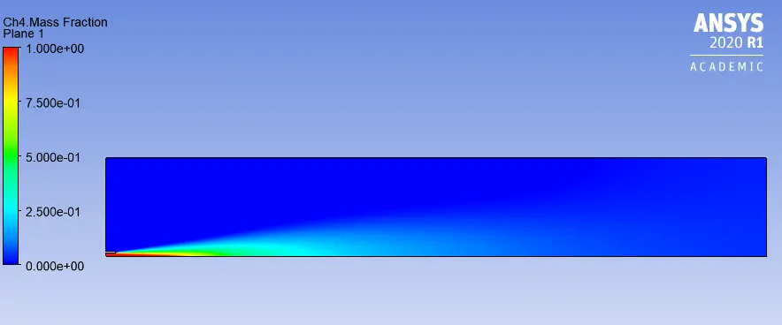
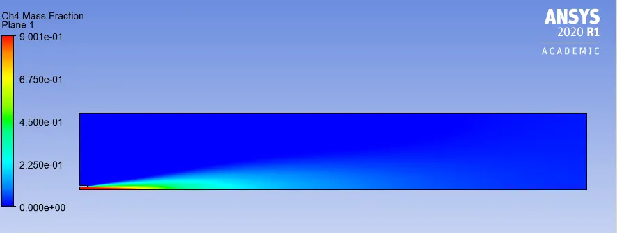
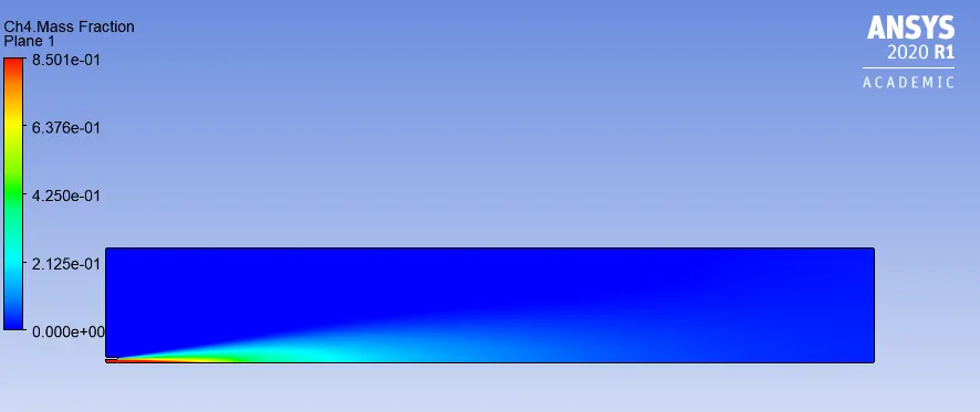
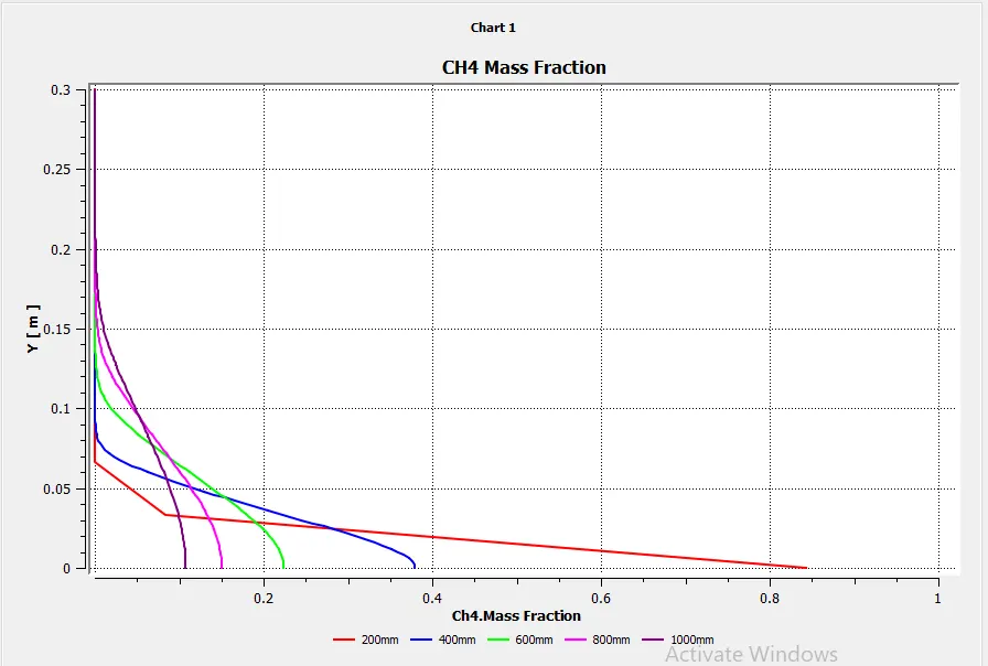
In the present system, Ch4 and Air produce from the fuel and air inlets. and there will be combustion present due to the mixing of CH4 and air. There is a small inlet of fuel as compared to the air inlet and when they mixed up, they produce different pollutants such as CH4, H2O, CO2, N2, O2, NOx emissions & soot formations at the outlet. We also use the water with the Ch4 at fuel inlet by mole fraction to observe its effect.
Modeling:
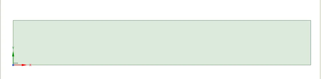
A 2D model was created using the ANSYS Spaceclaim. The fuel inlet was created for 10mm and the air inlet wsas created with 285mm. The length of the burner was set as 2000mm. The model for the burner can be seen below:
Mesh
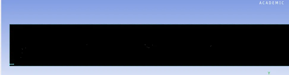
The model was then imported for meshing. Taking the simplicity of the model into consideration the quadilateral method of meshing is used because it gives more accurate results than that of the triangular meshing. Thus the meshing method of multizone was used. The total element size was considered to be 2mm. The total numver of elements are 150065 and the total number of nodes are 151237. The mesh can be seen below:
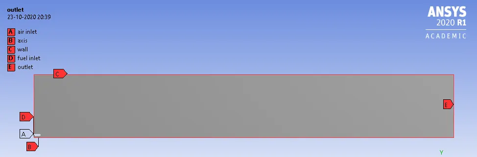
The different named selection were created and can be seen below:
Setup Physics and Simulation:
Solver: Steady State
Type: Pressure Based Solver
2D Space: Axisymmetric
Energy Equation: Enabled
Viscous Model: k-epsilon, standard wall function
Species Model: Species Transport
Reactions: Volumtric
Mixture Model: Methane Air
Turbulence Interaction: Eddy Dissipation
NOx Model: Thermal NOx
Soot Model: One Step
Species Defination: Fuel CH4
Oxidant O2
Boundary Condition: Fuel Inlet: 80m/s
Temperature: 300K
Species mass fraction at fuel inlet: CH4=1
Air Inlet:
Velocity : 0.5m/s
Thermal: 300K
Pecies Mass Fraction: O2- 0.23%
Initialisation: Hybrid
Here we used the Fuel as pure CO2.
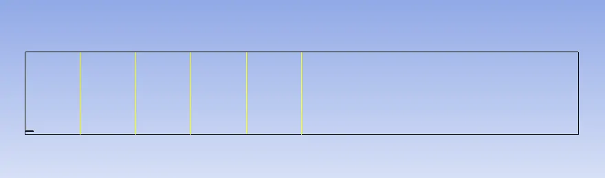
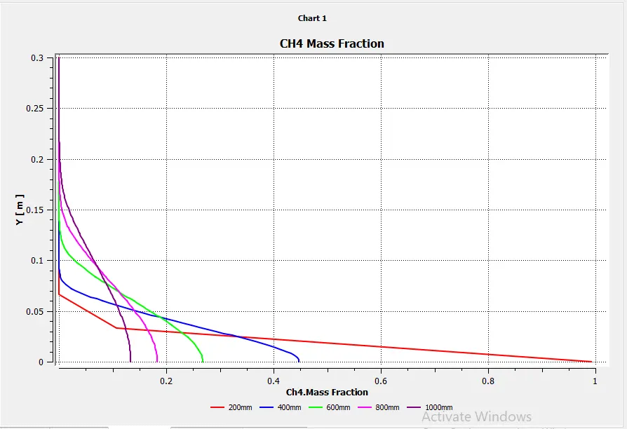
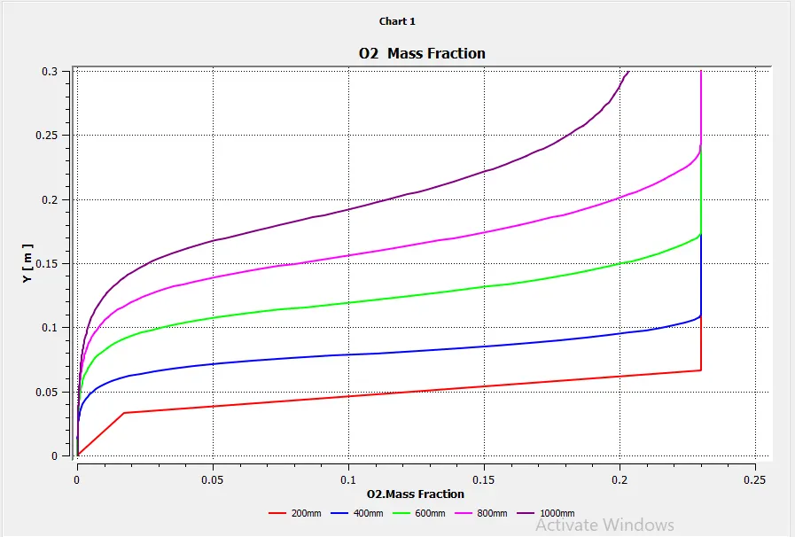
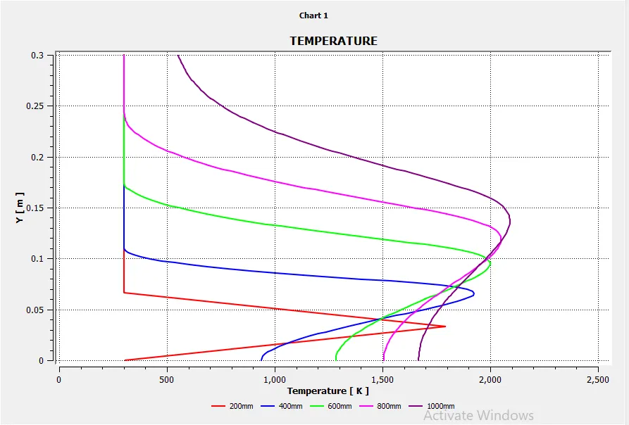
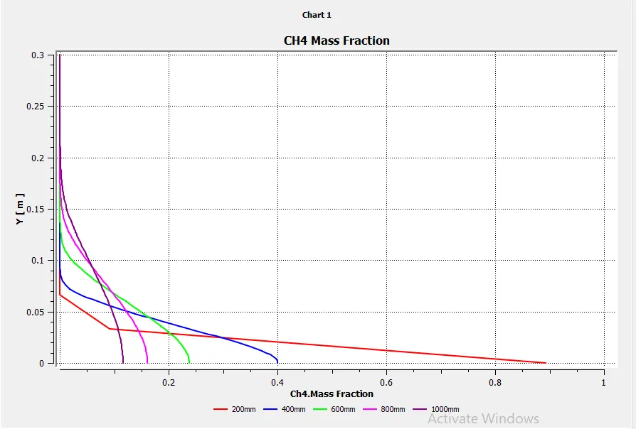
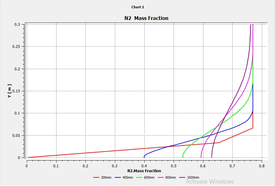
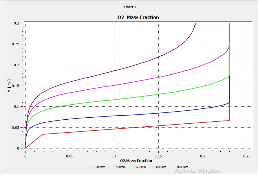
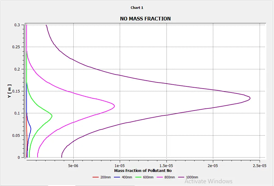
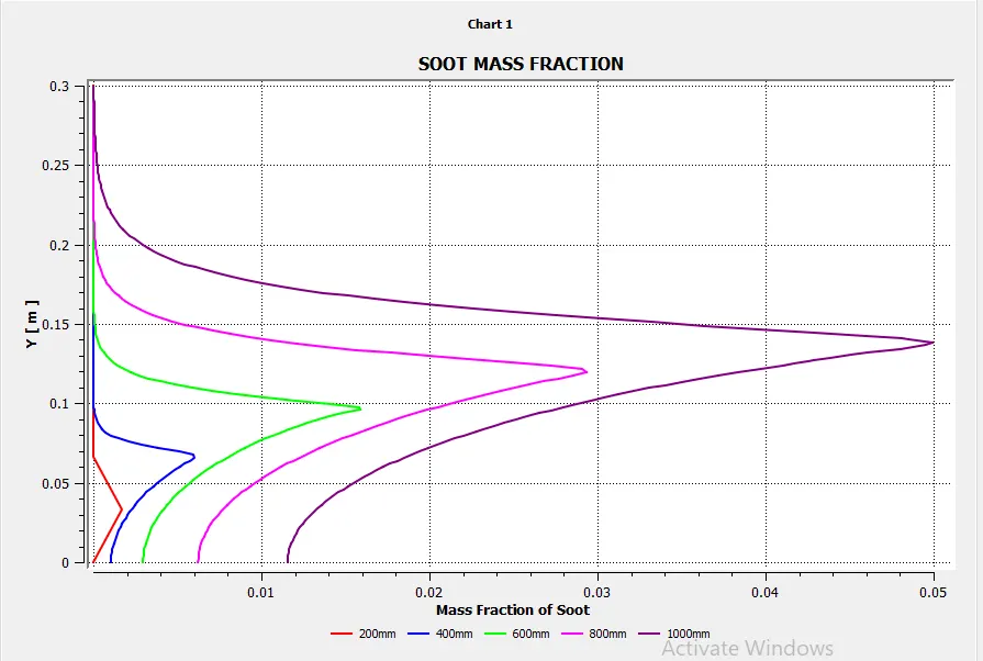
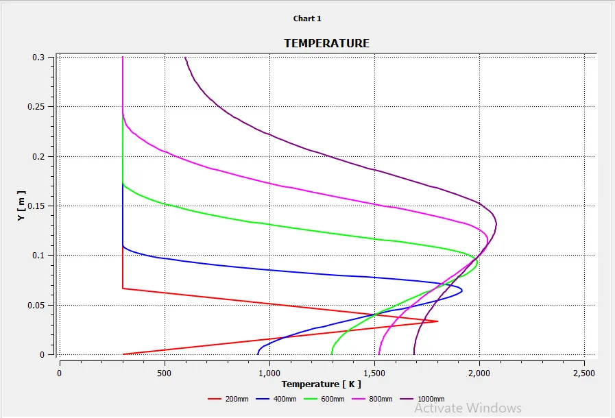
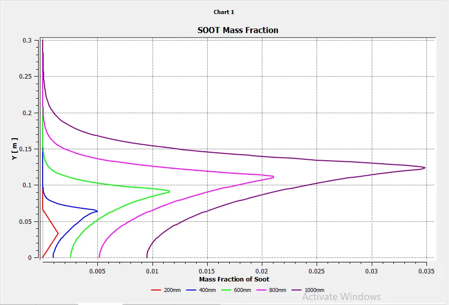
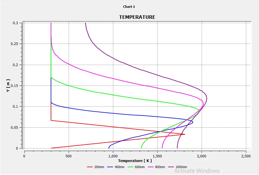
The plots can were plotted at different lines at distance of 200, 400, 600, 800 and 1000mm as shown below:
The results can be seen below:
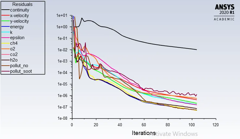
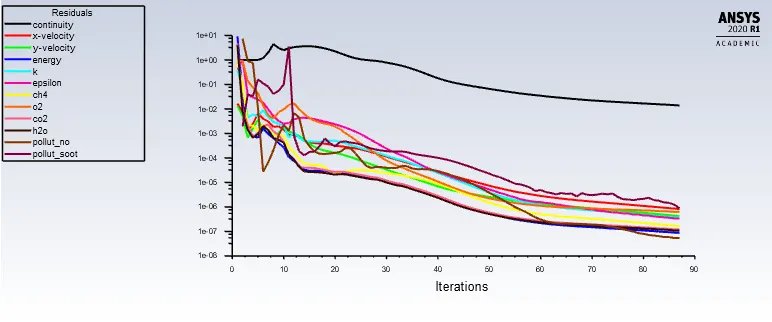
1. Residuals
2. CH4 mass fraction:
3. CH4 mass fraction plot
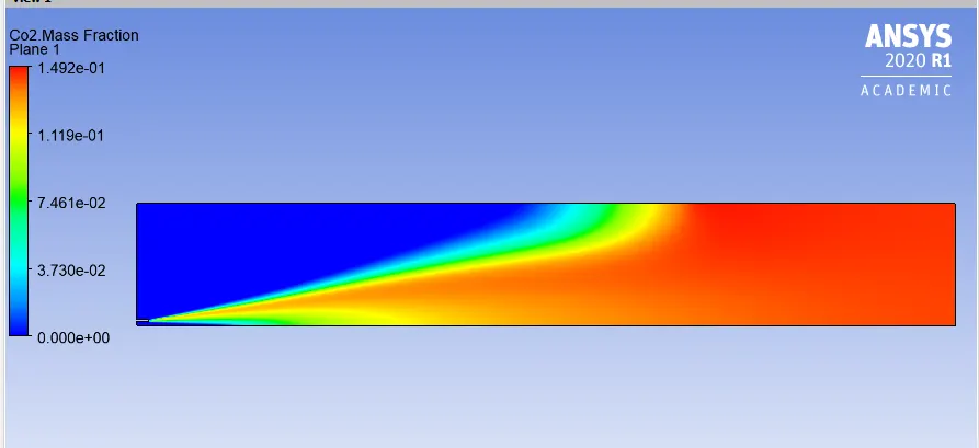
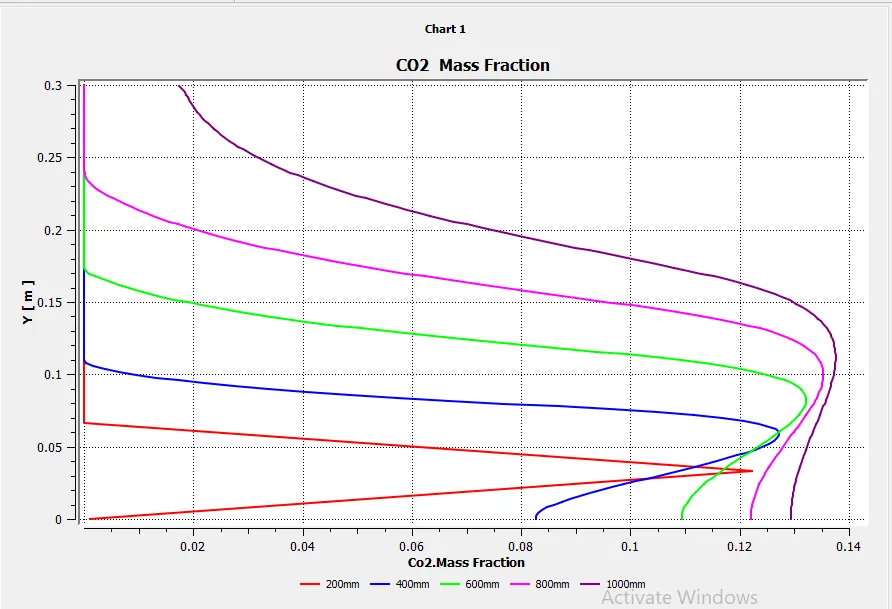
4.CO2 Mass Fraction
5. CO2 Mass Fraction Plot
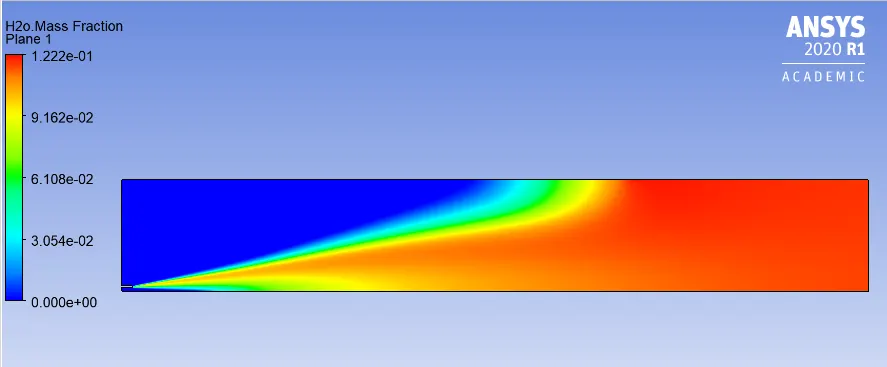
6.H2O Mass Fraction
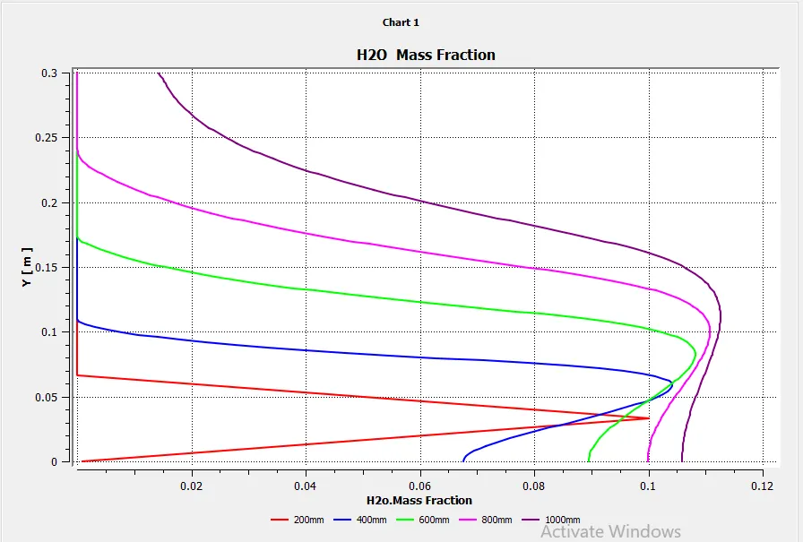
7. H2O Mass Fraction Plot
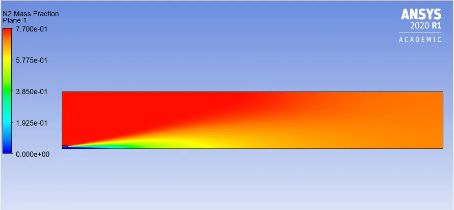
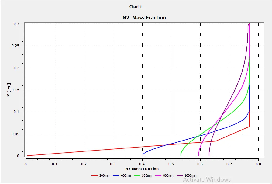
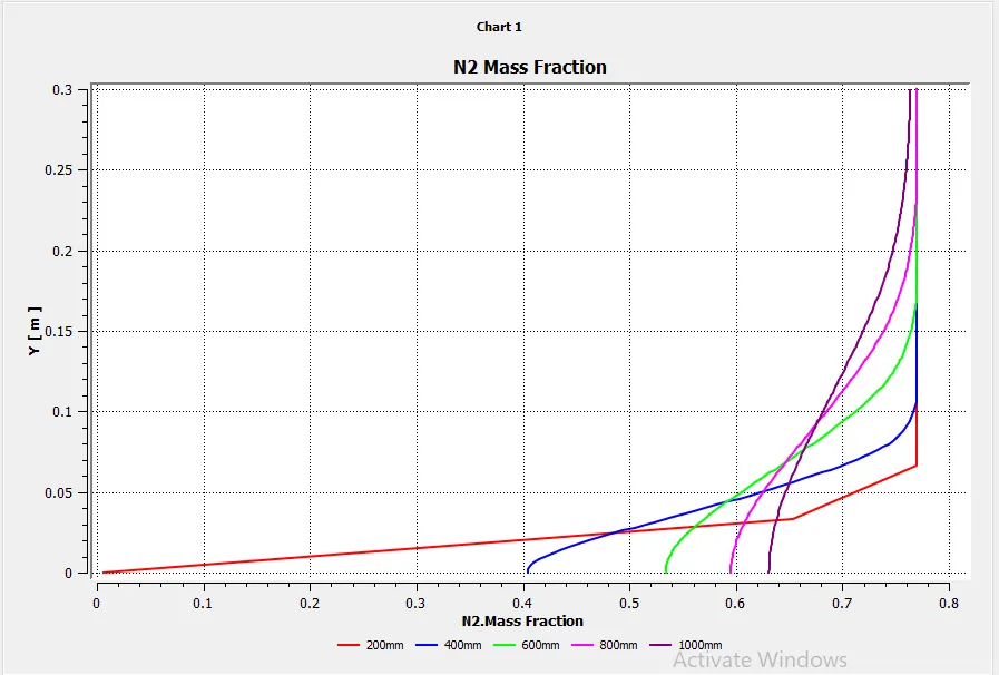
8. N2 mass fraction
9. N2 Mass fraction Plot
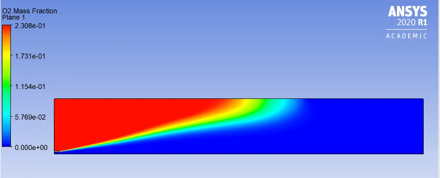
10. O2 Mass fraction
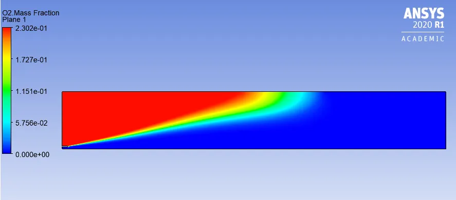
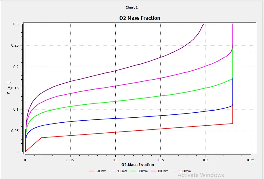
11. O2 Mass fraction Plot
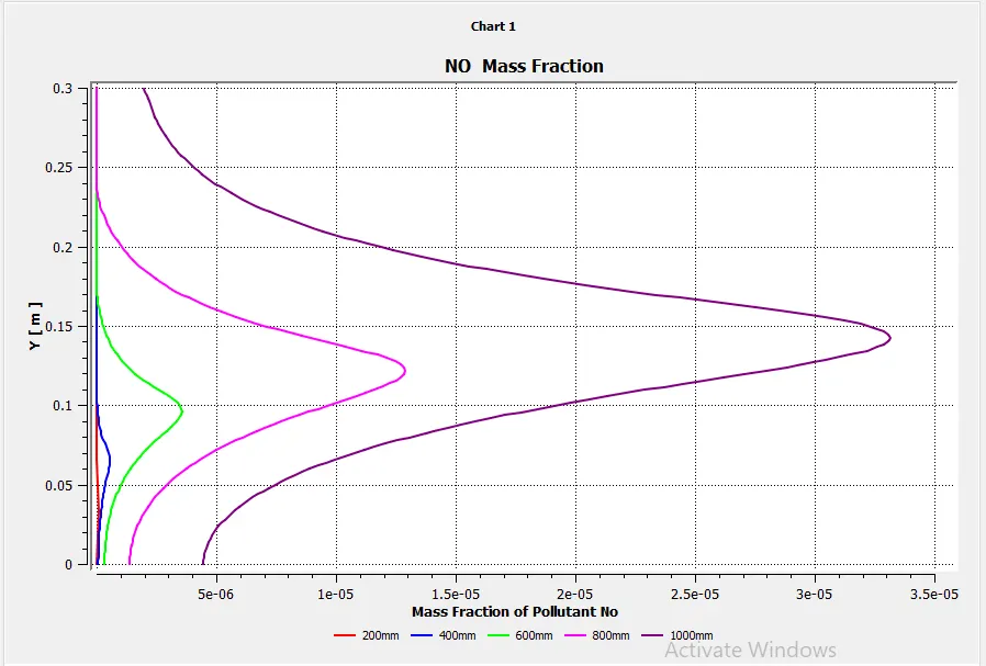
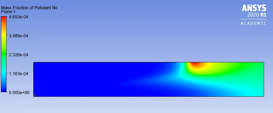
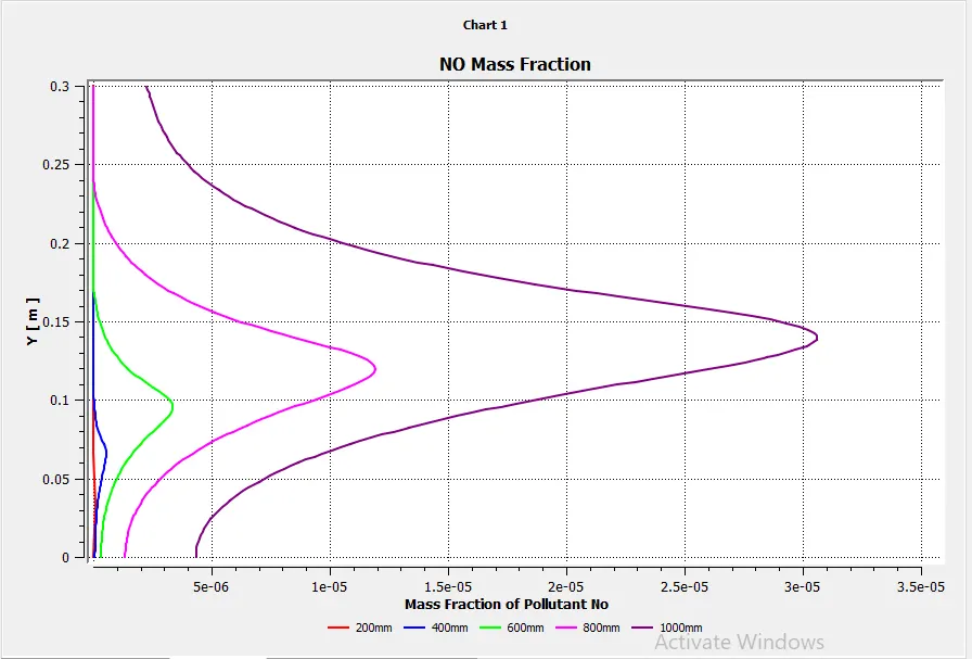
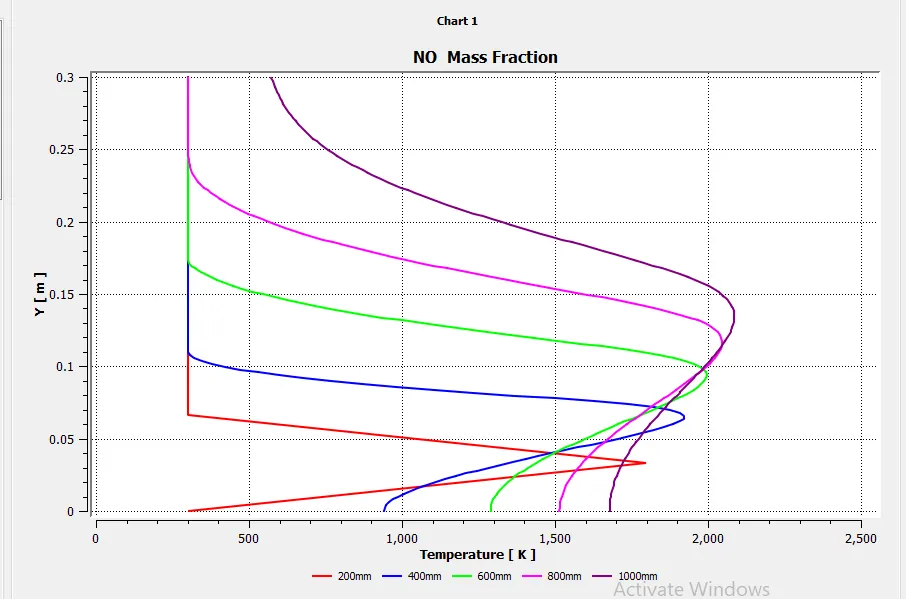
12. NO Pollutant mass Fraction
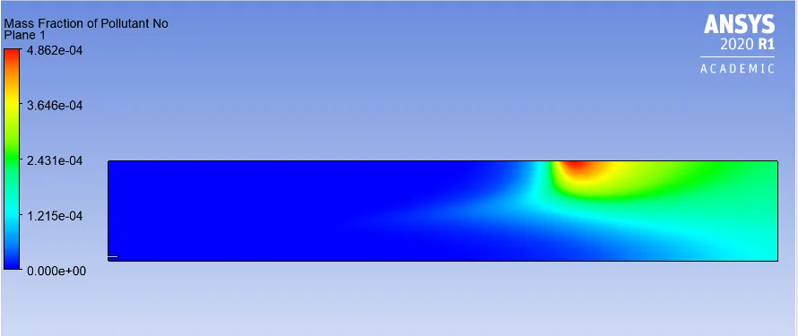
13.NO Pollutant mass Fraction Plot
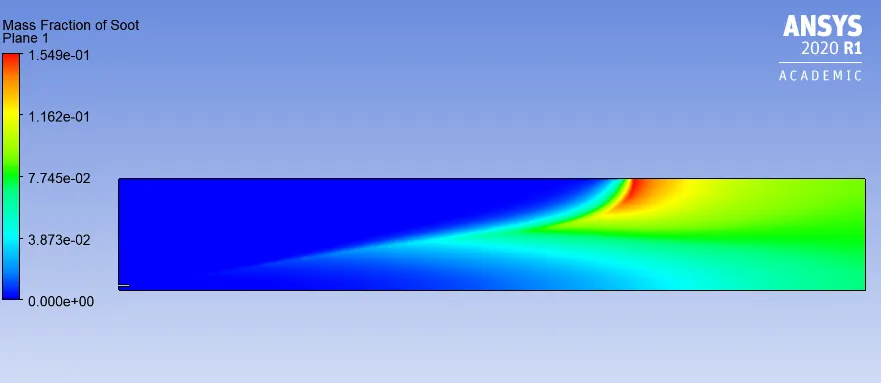
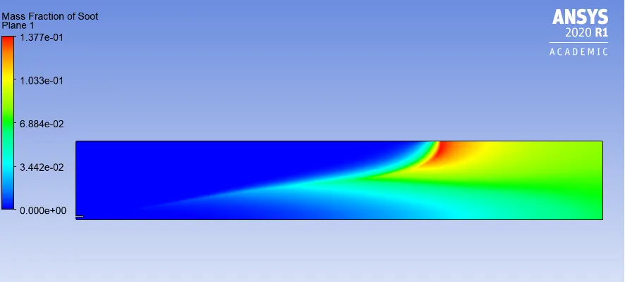
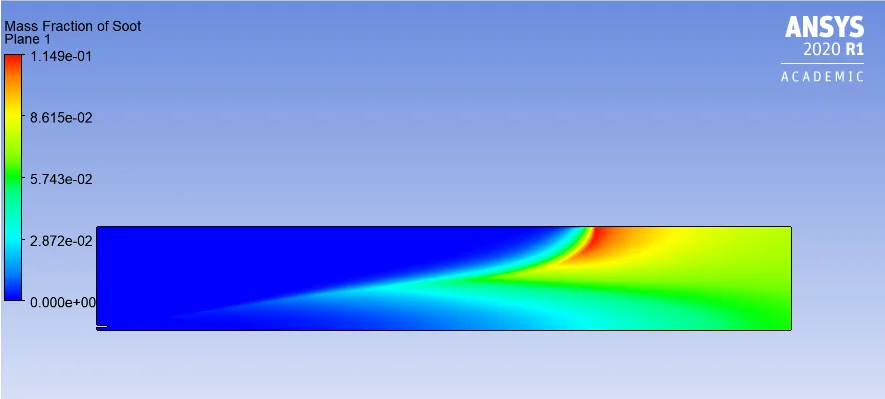
14. Soot Mass Fraction
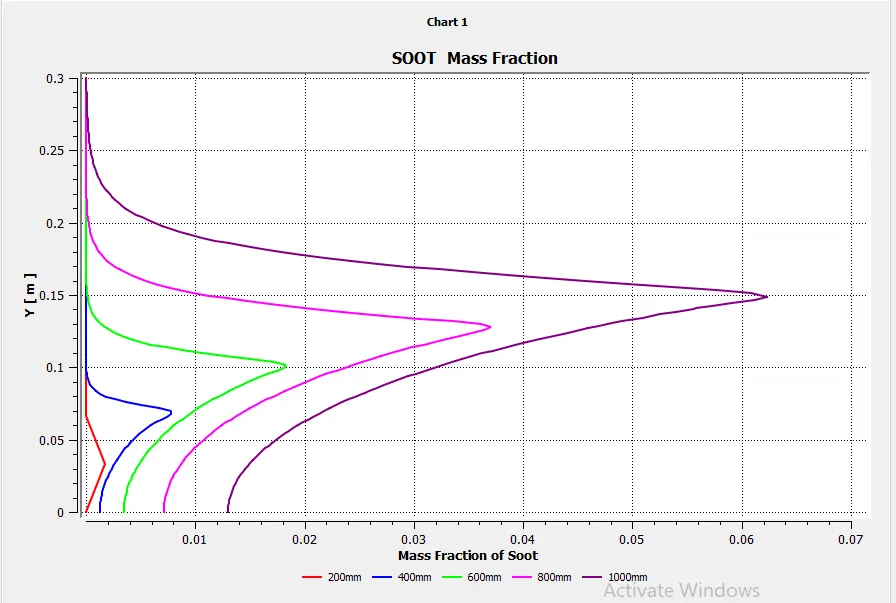
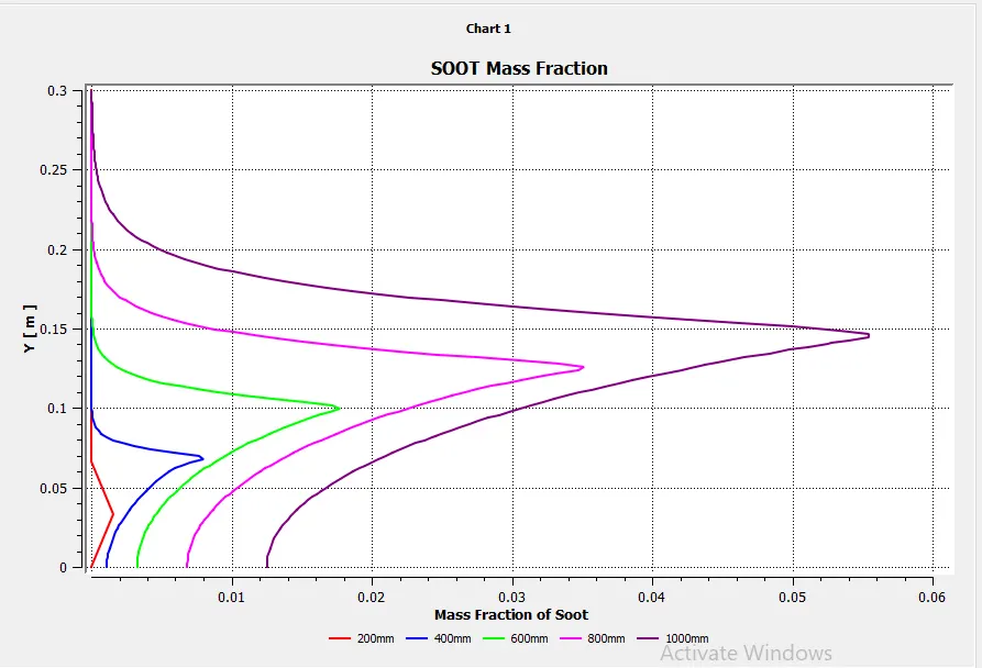
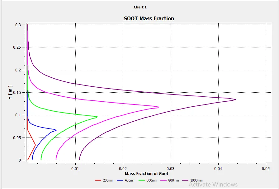
15.Soot Mass Fraction Plot
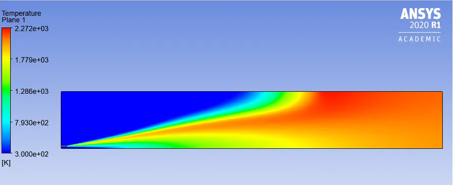
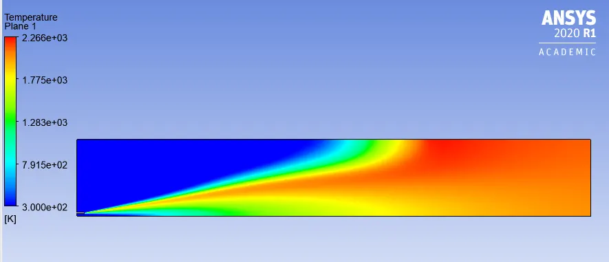
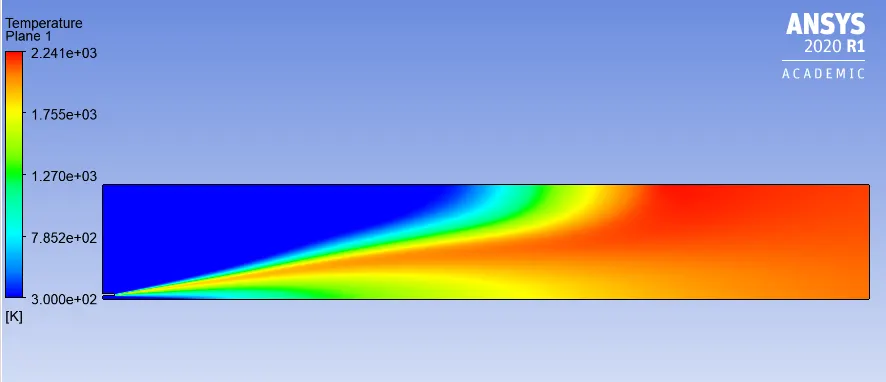
16. Temperature
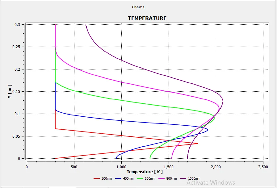
17. Temperature Plot
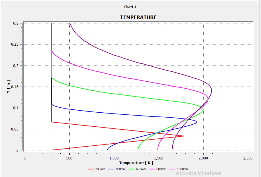
In second part of the challenge it is said that to study th eeffect of water mixture with inlet fuel.
Case I
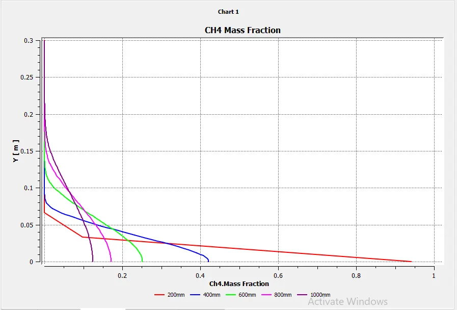
The inlet fuel is mixed with 5% v/v. Rest of the setup was kept same. The results can be seen below:
1. Residuals
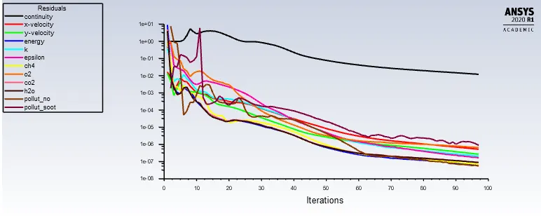
2. CH4 mass fraction:

3. CH4 mass fraction plot
4.CO2 Mass Fraction
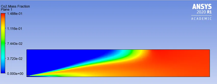
5. CO2 Mass Fraction Plot
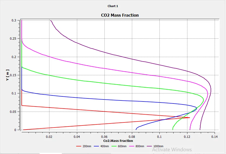
6.H2O Mass Fraction
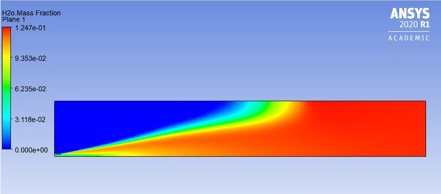
7. H2O Mass Fraction Plot
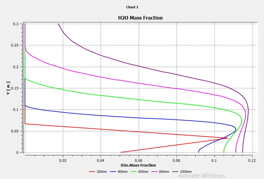
8. N2 mass fraction
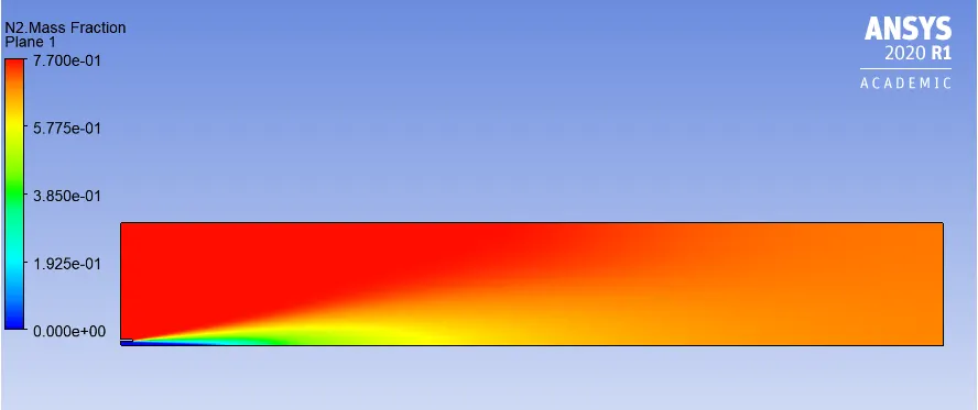
9. N2 Mass fraction Plot
10. O2 Mass fraction
11. O2 Mass fraction Plot
12. NO Pollutant mass Fraction
13.NO Pollutant mass Fraction Plot
14. Soot Mass Fraction
15.Soot Mass Fraction Plot
16. Temperature
17. Temperature Plot
Case II
The inlet fuel is mixed with 10% v/v. Rest of the setup was kept same. The results can be seen below:
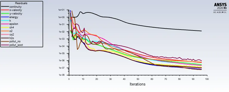
1. Residuals
2. CH4 mass fraction:
3. CH4 mass fraction plot
4.CO2 Mass Fraction
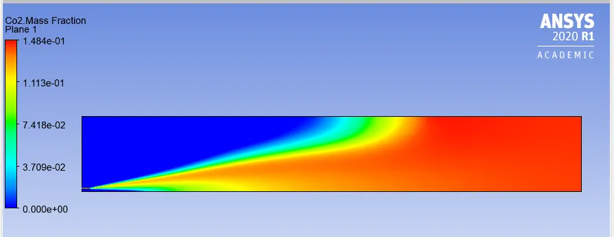
5. CO2 Mass Fraction Plot
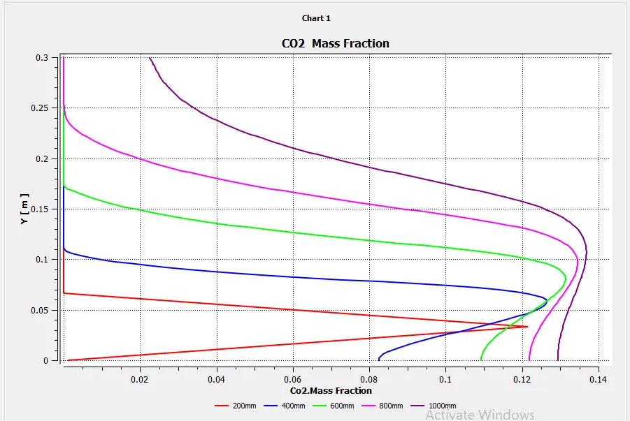
6.H2O Mass Fraction
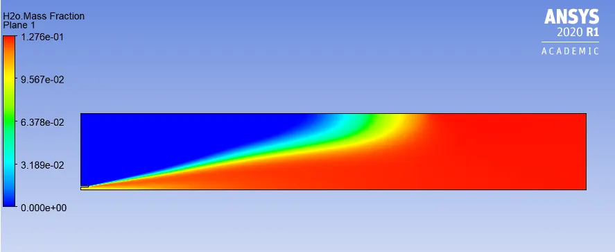
7. H2O Mass Fraction Plot
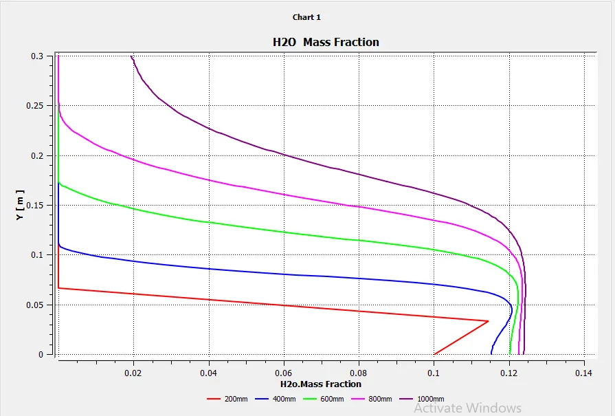
8. N2 mass fraction
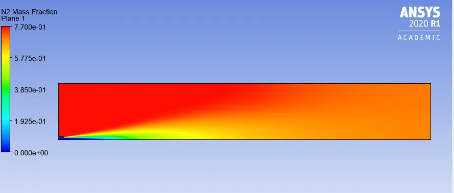
9. N2 Mass fraction Plot
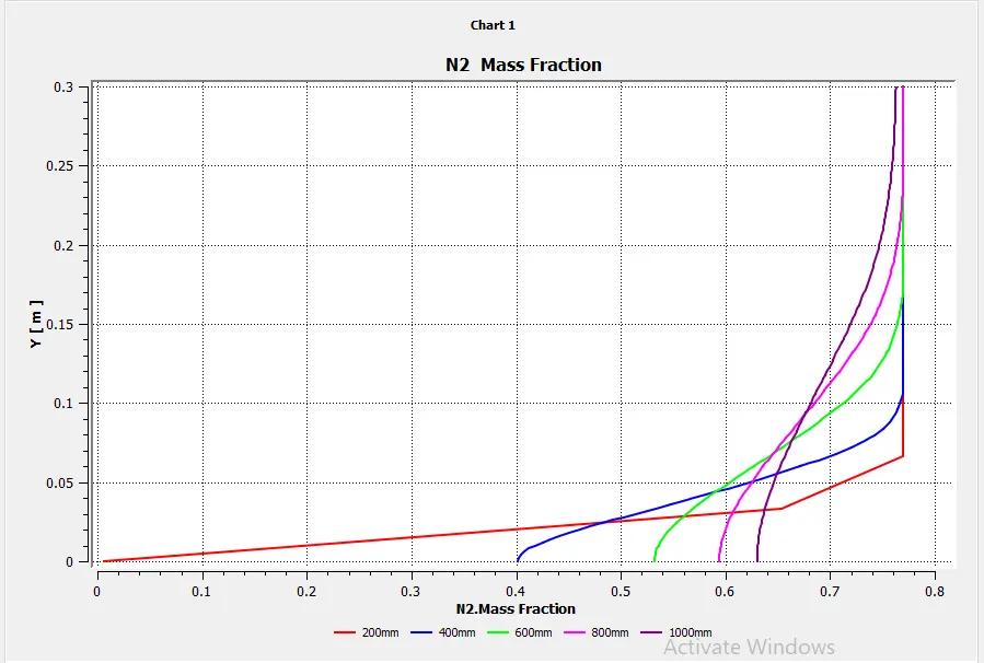
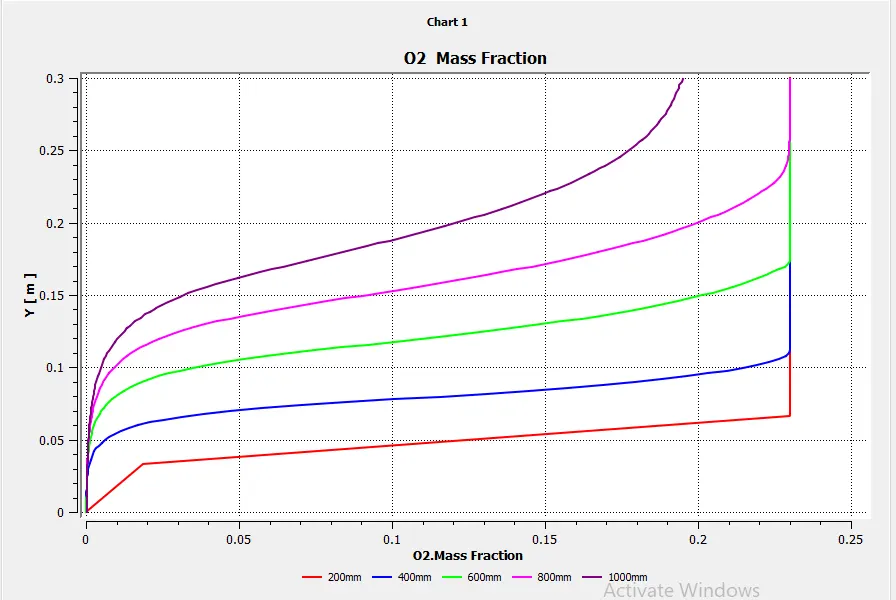
10. O2 Mass fraction

11. O2 Mass fraction Plot
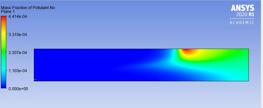
12. NO Pollutant mass Fraction
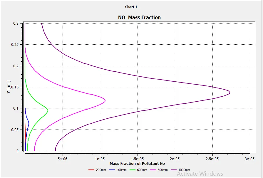
13.NO Pollutant mass Fraction Plot
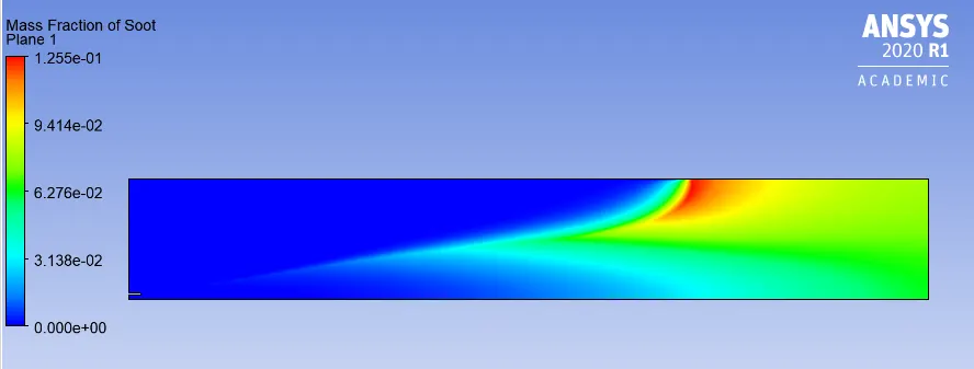
14. Soot Mass Fraction
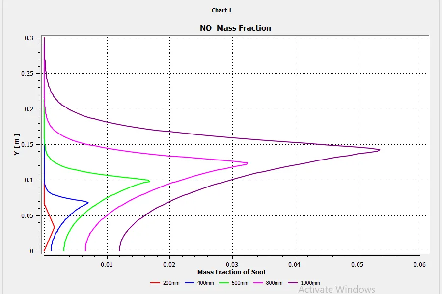
15.Soot Mass Fraction Plot
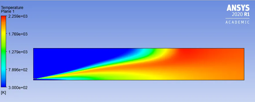
16. Temperature
17. Temperature Plot
Case III
The inlet fuel is mixed with 15% v/v. Rest of the setup was kept same. The results can be seen below:
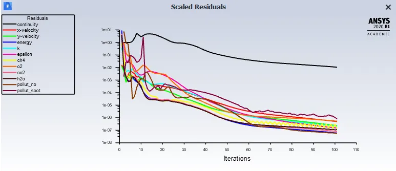
1. Residuals
2. CH4 mass fraction:
3. CH4 mass fraction plot
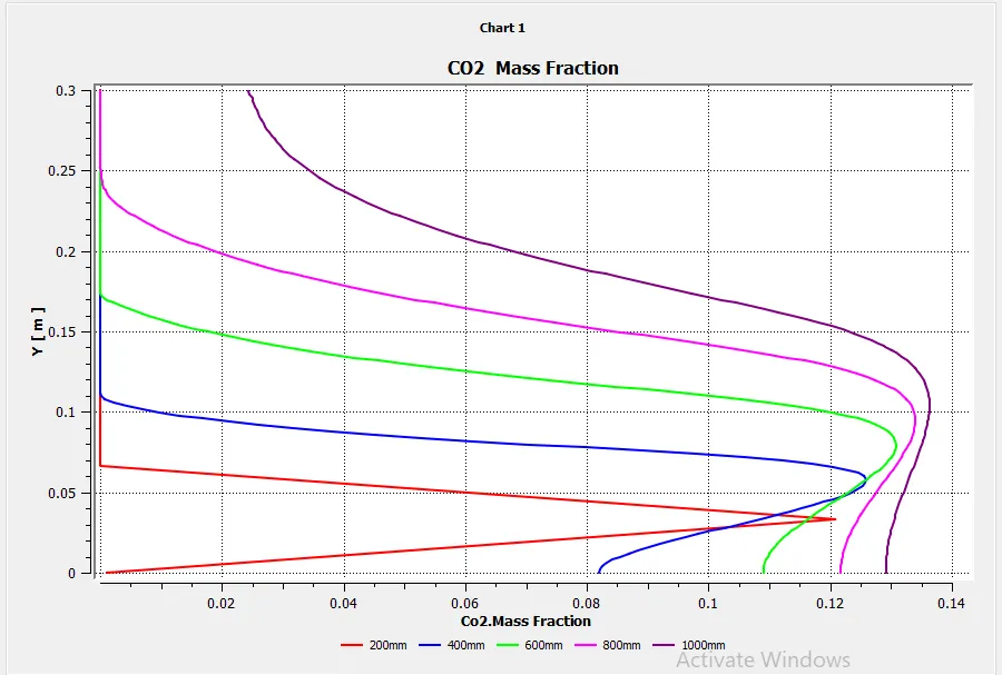
4.CO2 Mass Fraction
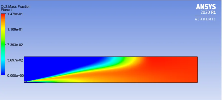
5. CO2 Mass Fraction Plot
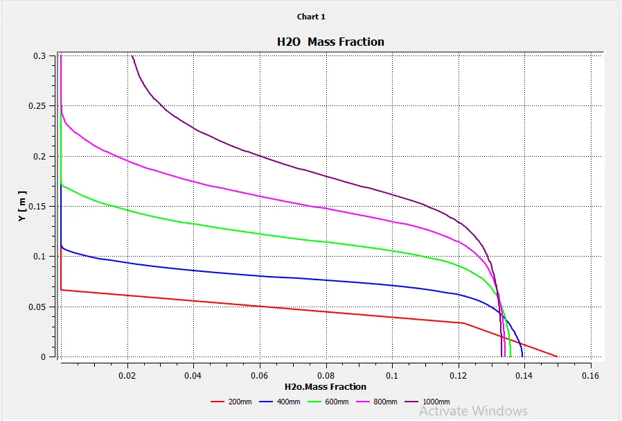
6.H2O Mass Fraction
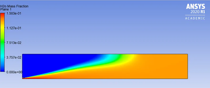
7. H2O Mass Fraction Plot
8. N2 mass fraction
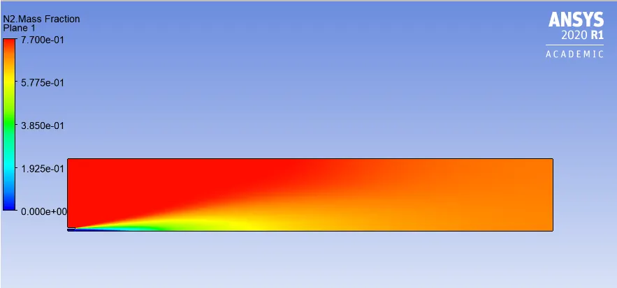
9. N2 Mass fraction Plot
10. O2 Mass fraction
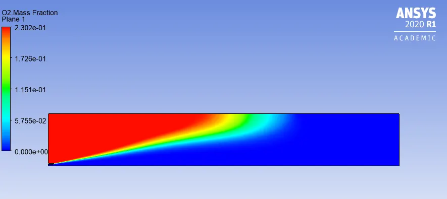
11. O2 Mass fraction Plot
12. NO Pollutant mass Fraction
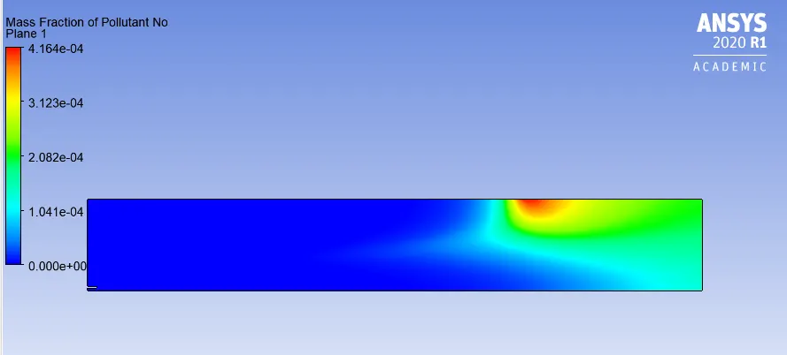
13.NO Pollutant mass Fraction Plot
14. Soot Mass Fraction
15.Soot Mass Fraction Plot
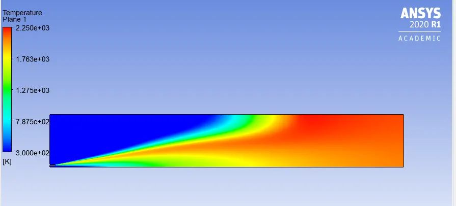
16. Temperature
17. Temperature Plot
Case IV
The inlet fuel is mixed with 20% v/v. Rest of the setup was kept same. The results can be seen below:
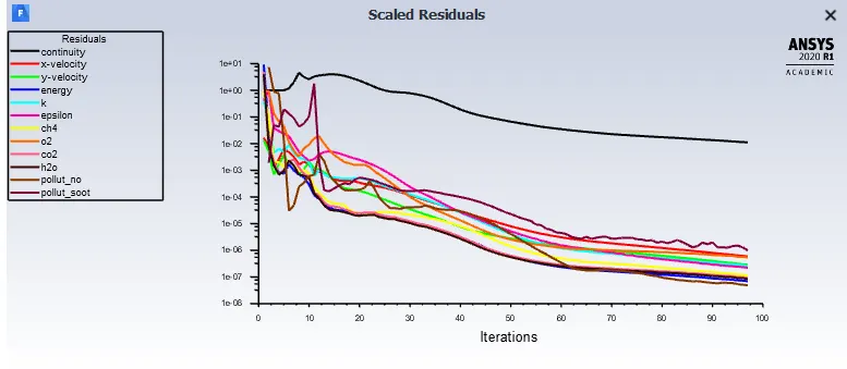
1. Residuals
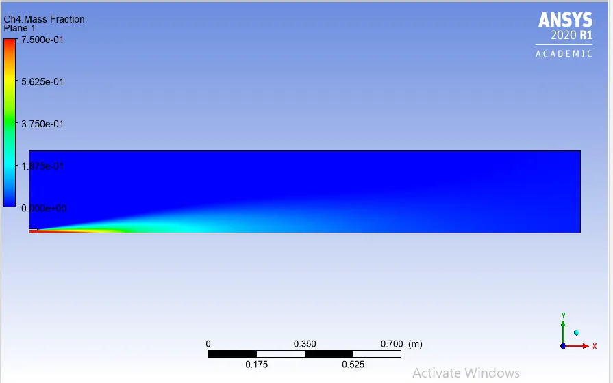
2. CH4 mass fraction:
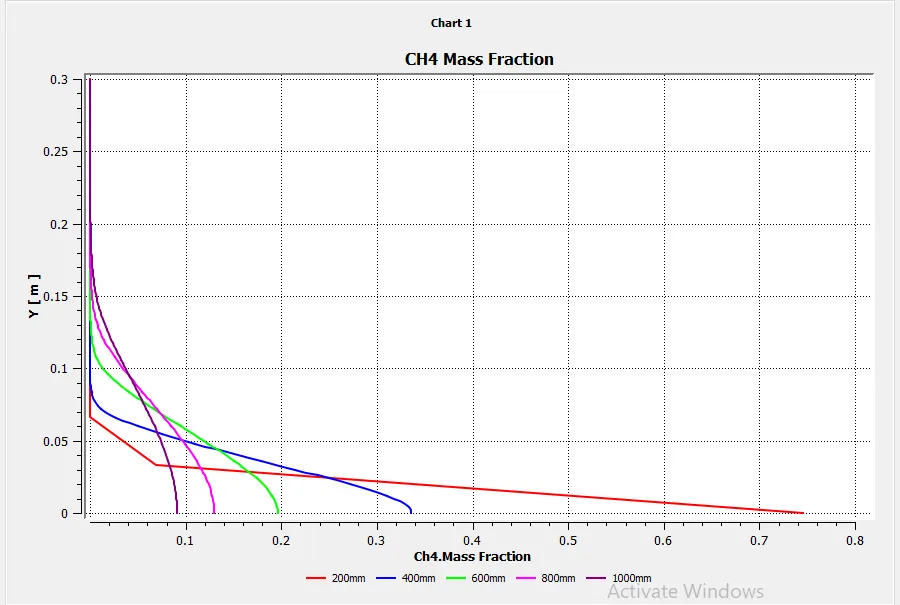
3. CH4 mass fraction plot
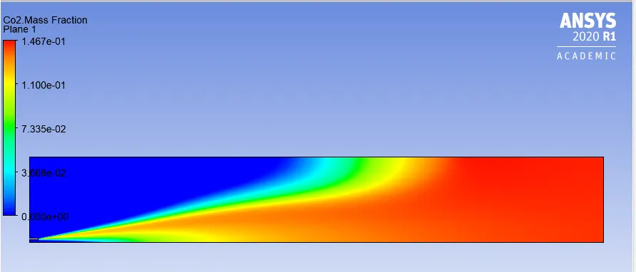
4.CO2 Mass Fraction
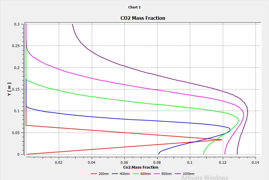
5. CO2 Mass Fraction Plot
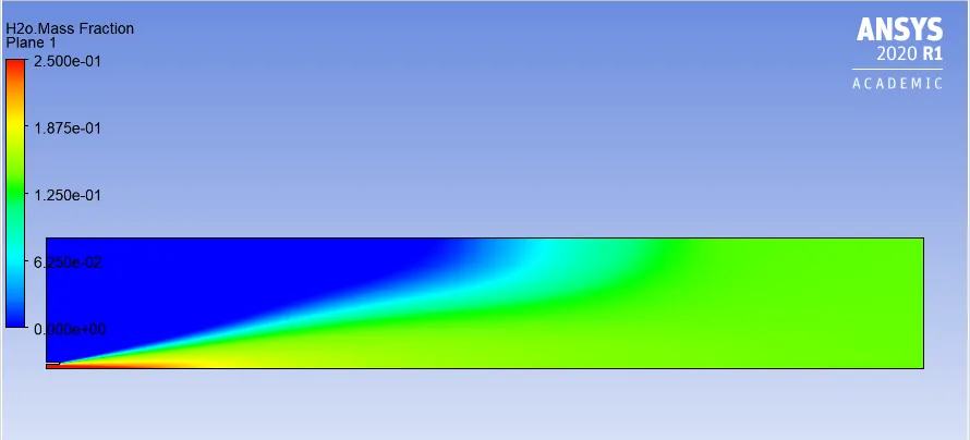
6.H2O Mass Fraction
7. H2O Mass Fraction Plot
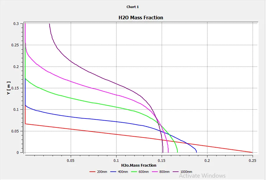
8. N2 mass fraction
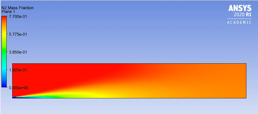
9. N2 Mass fraction Plot
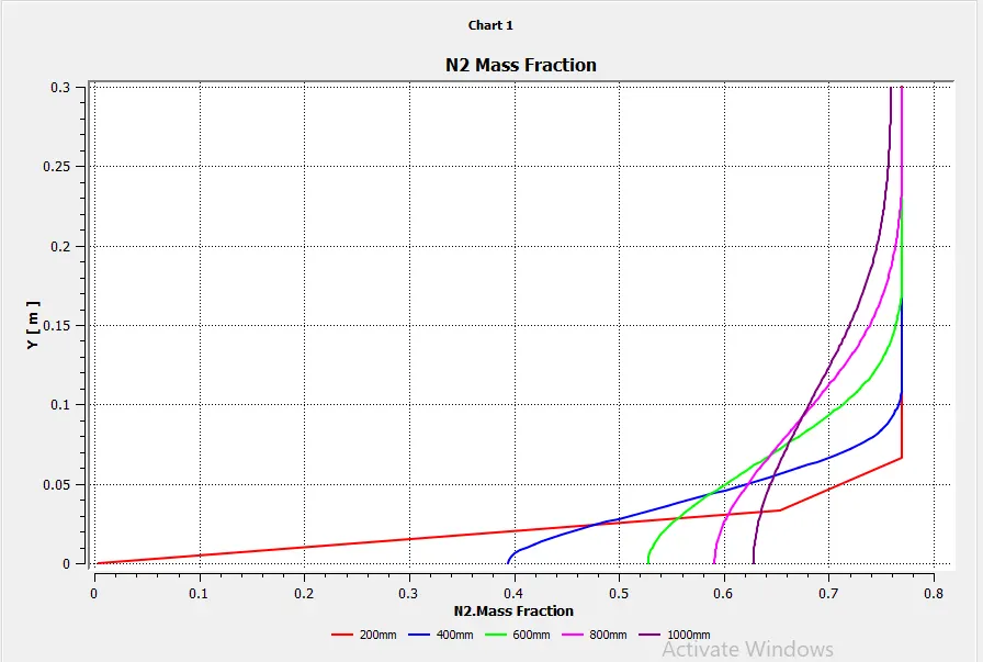
10. O2 Mass fraction
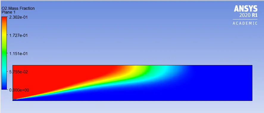
11. O2 Mass fraction Plot
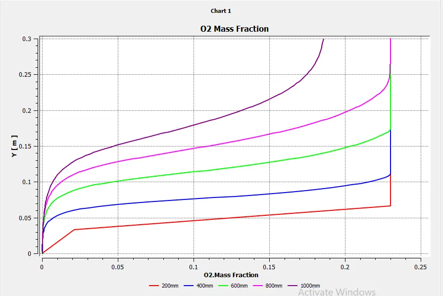
12. NO Pollutant mass Fraction
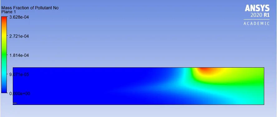
13.NO Pollutant mass Fraction Plot
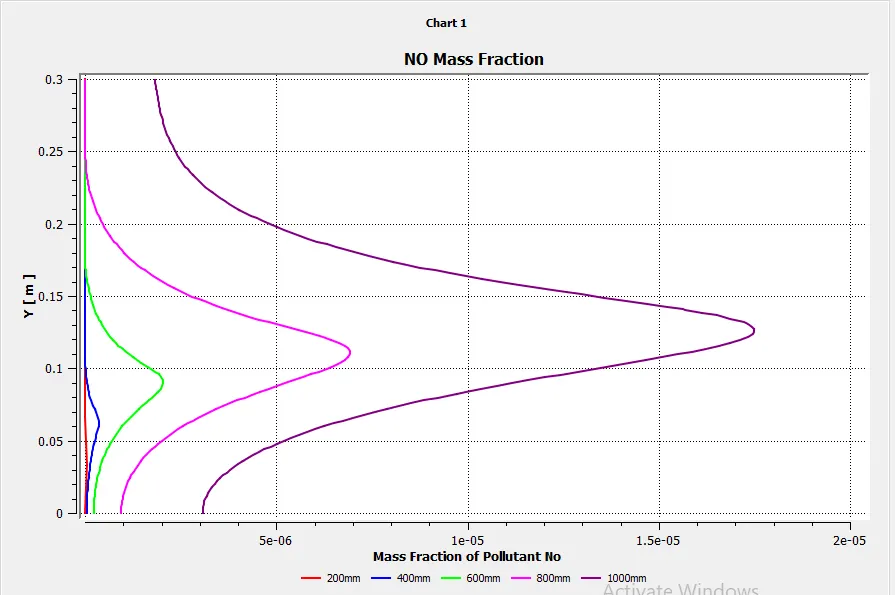
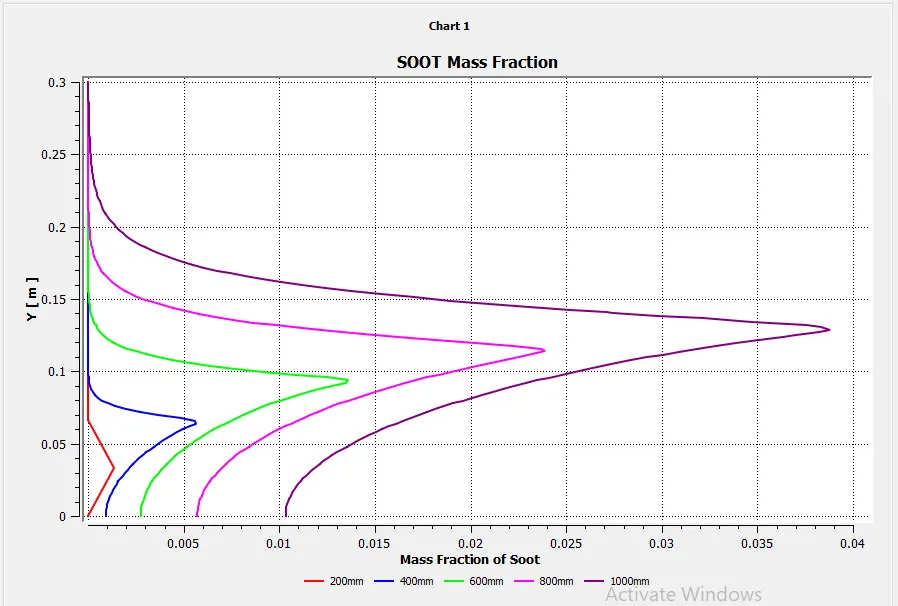
14. Soot Mass Fraction
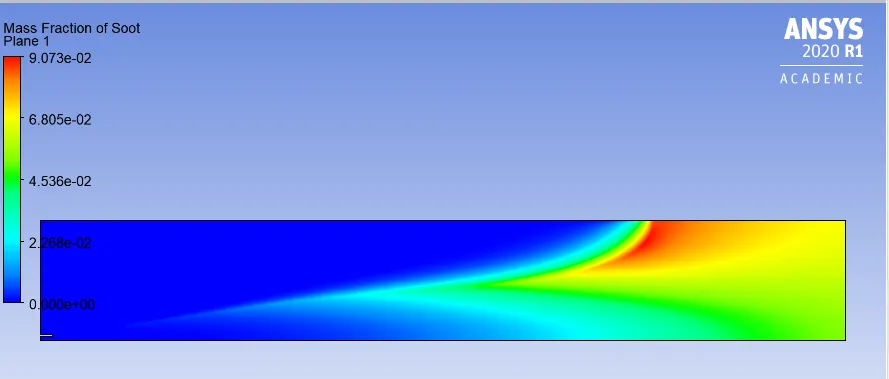
15.Soot Mass Fraction Plot
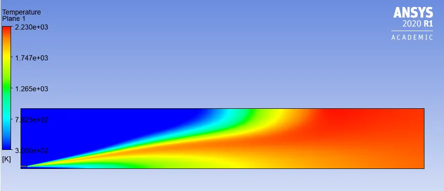
16. Temperature
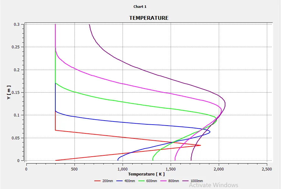
17. Temperature Plot
Case V
The inlet fuel is mixed with 25% v/v. Rest of the setup was kept same. The results can be seen below:
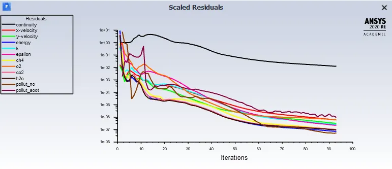
1. Residuals
2. CH4 mass fraction:
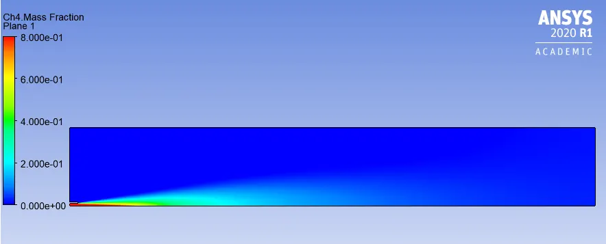
3. CH4 mass fraction plot
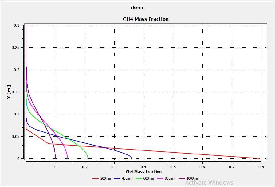
4.CO2 Mass Fraction
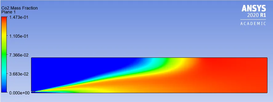
5. CO2 Mass Fraction Plot
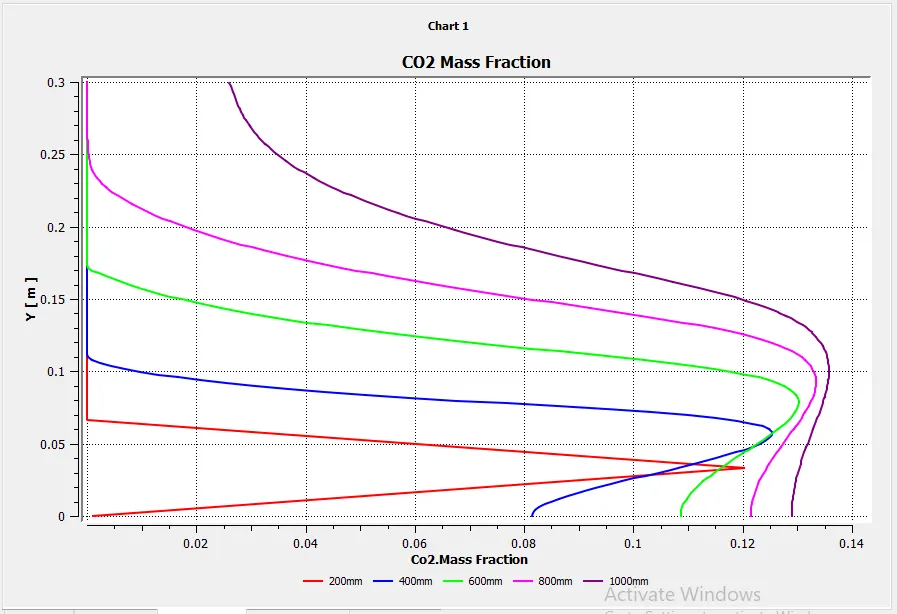
6.H2O Mass Fraction
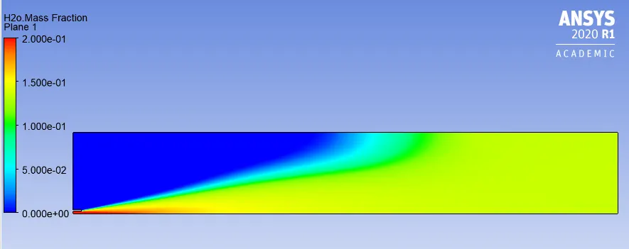
7. H2O Mass Fraction Plot
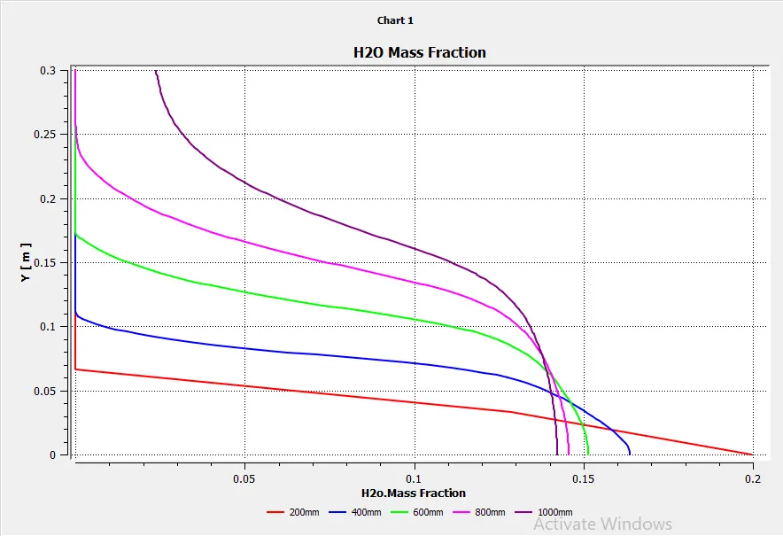
8. N2 mass fraction
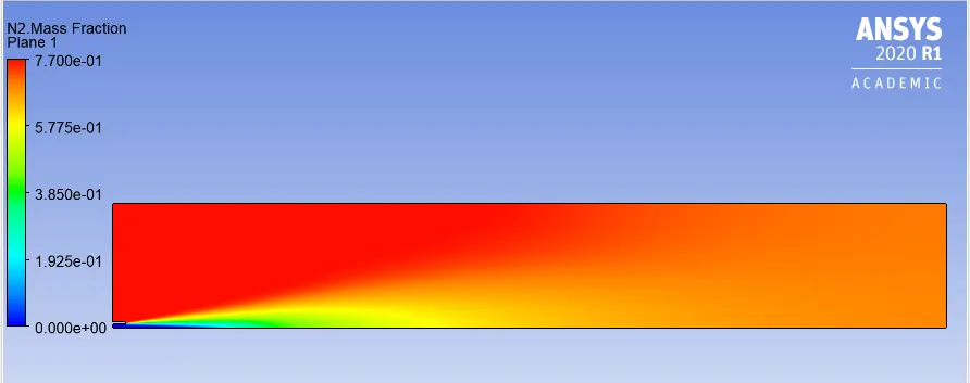
9. N2 Mass fraction Plot
10. O2 Mass fraction
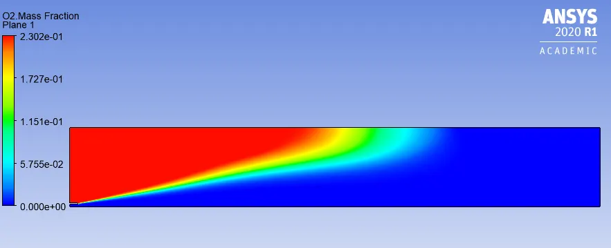
11. O2 Mass fraction Plot
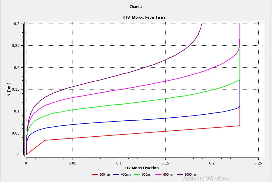
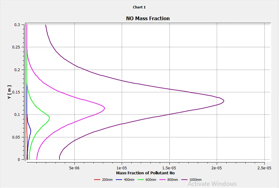
12. NO Pollutant mass Fraction
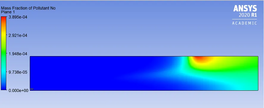
13.NO Pollutant mass Fraction Plot
14. Soot Mass Fraction
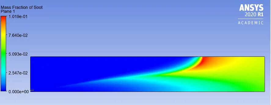
15.Soot Mass Fraction Plot
16. Temperature
17. Temperature Plot
Case VI
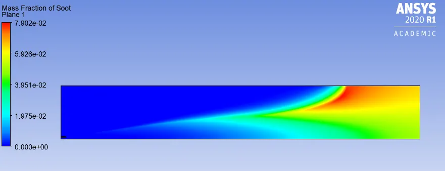
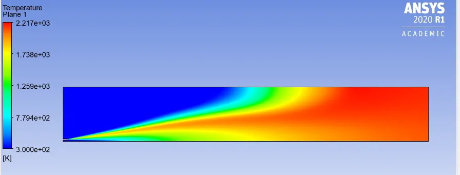
The inlet fuel is mixed with 30% v/v. Rest of the setup was kept same. The results can be seen below:
1. Residuals
2. CH4 mass fraction:
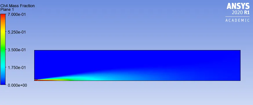
3. CH4 mass fraction plot
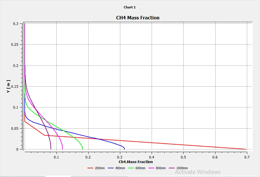
4.CO2 Mass Fraction
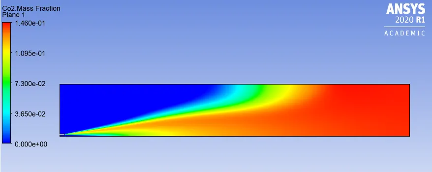
5. CO2 Mass Fraction Plot
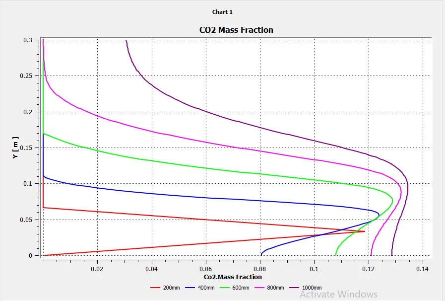
6.H2O Mass Fraction
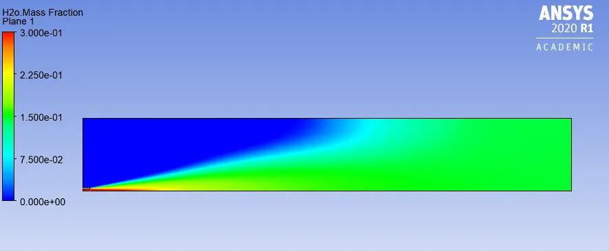
7. H2O Mass Fraction Plot
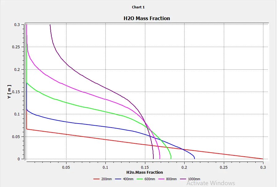
8. N2 mass fraction
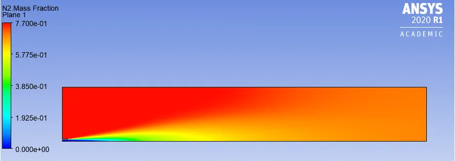
9. N2 Mass fraction Plot
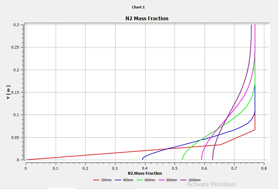
10. O2 Mass fraction
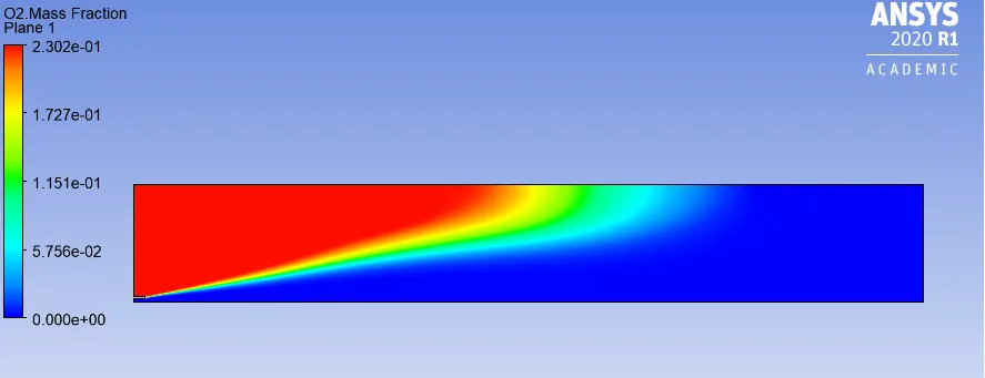
11. O2 Mass fraction Plot
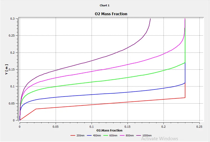
12. NO Pollutant mass Fraction
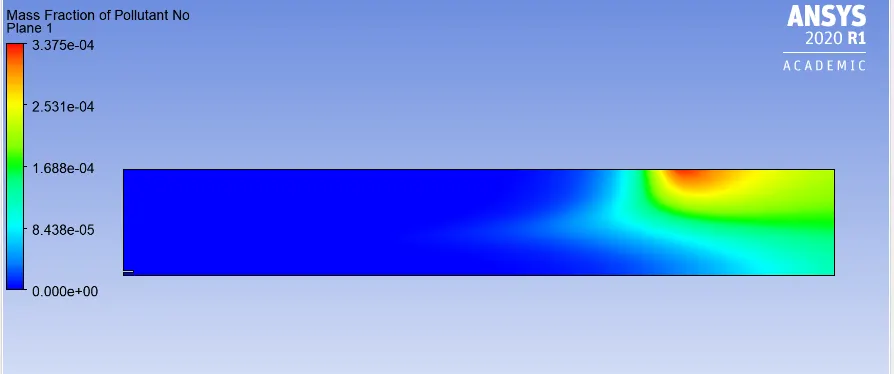
13.NO Pollutant mass Fraction Plot
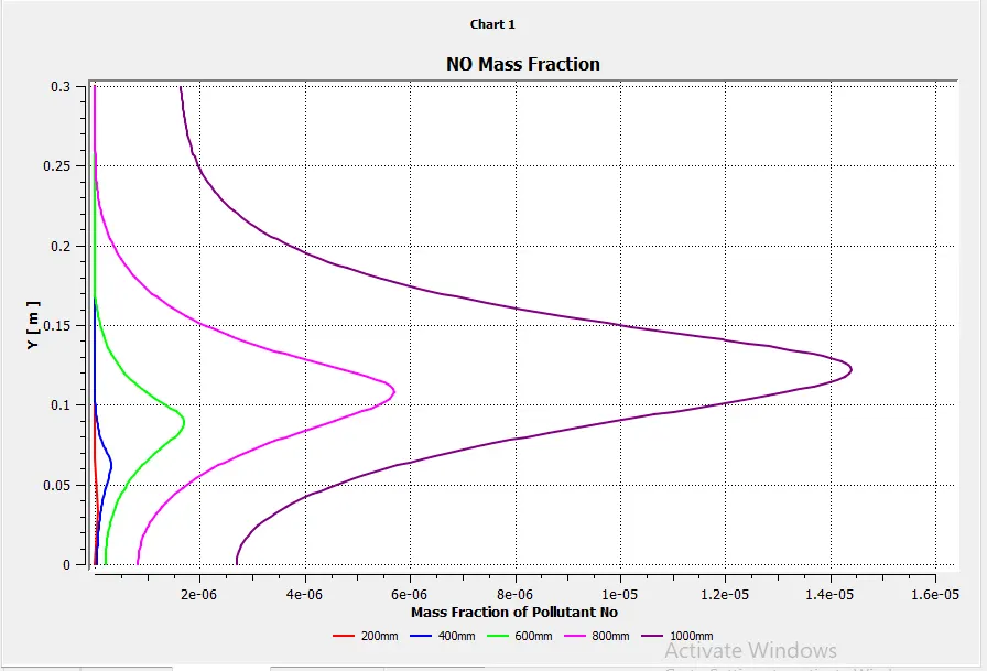
14. Soot Mass Fraction
15.Soot Mass Fraction Plot
16. Temperature
17. Temperature Plot
The result for the different water composition can be seen tabulated below:
| S.No | Mole Fraction of Water | CH4 | CO2 | H2O | N2 | O2 | NO | Soot | Mean Temperature | Maximum Temperature |
| 1 | 0 | 0.0363339 | 0.144115 | 0.117987 | 0.701556 | 8.387e-6 | 0.000198 | 0.08325 | 2104.25 | 2272 |
| 2 | 5 | 0.0324128 | 0.144034 | 0.12239 | 0.701155 | 8.588e-6 | 0.000194 | 0.07776 | 2111.9 | 2266.06 |
| 3 | 10 | 0.02837 | 0.143964 | 0.126847 | 0.700805 | 1.02e-5 | 0.000191 | 0.07417 | 2120.2 | 2258.59 |
| 4 | 15 | 0.0242886 | 0.143897 | 0.131354 | 0.700447 | 1.28e-5 | 0.000189 | 0.0709 | 2128.74 | 2250.2 |
| 5 | 20 | 0.02017 | 0.143819 | 0.135899 | 0.700087 | 1.712e-5 | 0.000187 | 0.0672 | 2137.3 | 2240.64 |
| 6 | 25 | 0.0160161 | 0.143745 | 0.140495 | 0.699719 | 2.47e-5 | 0.000187 | 0.0637 | 2146.06 | 2229.87 |
| 7 | 30 | 0.018219 | 0.143661 | 0.145135 | 0.69934 | 4.122e-5 | 0.000189 | 0.05952 | 2154.78 | 2217.43 |
Conclusion:
- Combustion occours due to the turbulent mixing of CH4 and air at inlet and produces soot and pollutant at the outlet.
- As we add H20 with fuel it delays the ignitions and allows better mixing of fuel.
- Mass fraction of Pollutant No (NOx) decreases with an increase in addition to H20 at the fuel inlet that is good as per government norms.
- Mass fraction of soot decreases with increase in water fraction.
- Temperature also increases with increase in H20 concentration.