Challenge 3
Aim:
- What are the sectional properties we need upfront for designing a metro viaduct? What is the supporting software for identifying the sectional properties and designing them?
- Explain the detailed steps involved how elements are created in STAAD Pro and how are the inputs for sectional properties assigned?
- What are SLS combinations used for live loads, with respect to impact factor and how the moments for the section are derived?
- What is prestressing in girders? What are advantages of Prestressed girders in a metro project.
- Explain about prestressing losses? What are different type of prestressing losses and mention the significance of the prestressing losses?
- How a girder is being prestressed while fabrication? Explain the components/materials used during the prestressing?
- How are stresses in the girder calculated with the resultant prestressing losses?
- Explain the step wise procedure of transverse analysis of open web structure of U girders in STAAD pro along with how the vehicle parameters and loadings are fed in the STAAD software.
- How is the longitudinal analysis of open web structure of U girder performed, final design bending moments and axial stresses are extracted? Explain the software procedure for extracting the same.
Introduction :
This week explains about design aspects of open web girder and modelling in Staad based on Finite element method. Longitudinal analysis and transverse anaysis of the girder is done by separate modelling in staad. Loss of prestress force is calculated and final prestress force available to take up external load is obtained.
Procedure & Result :
1) What are the sectional properties we need upfront for designing a metro viaduct? What is the supporting software for identifying the sectional properties and designing them?
Ans. Sectional properties required for designing metro viaduct are :
Area of girder
Perimeter
Bounding Box coordinates
Centroid
Moment of Inertia of girder in X & Y axis
The software used for identifying these sectional properties is Autocad. We can draw the section in autocad as per required dimensions and find out the above mentioned sectional properties.
2) Explain the detailed steps involved how elements are created in STAAD Pro and how are the inputs for sectional properties assigned?
Ans.
To create any element im staad pro first we need to create nodes for that element. Node value is entered in the dialog box that appears when we open staad as shown below:
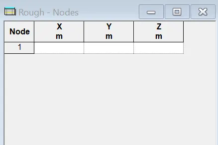
Suppose we need to create a beam element of 0.5m in X direction we input the following node values in the dialog box.
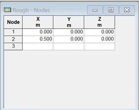
The node is created as follows:
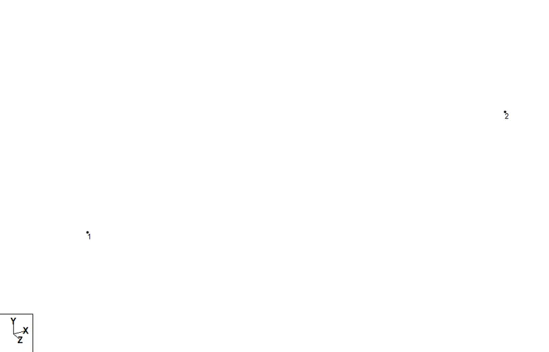
Now click on add beam and join the nodes
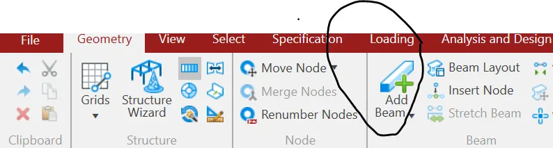
Now the beam is created
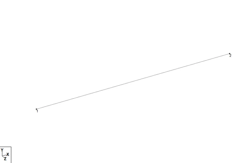
Now to add sectional properties following procedure is followed:
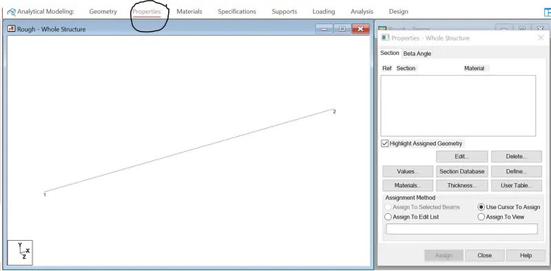
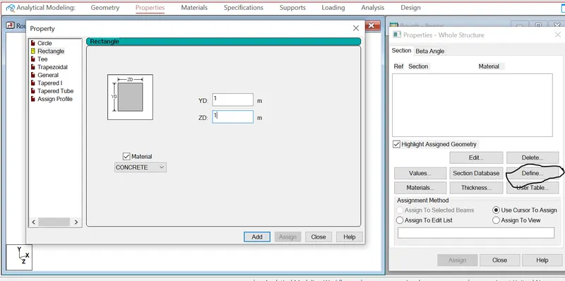
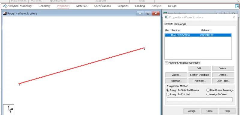
When we click on assign to selected beams the rectangle property with concrete material is assigned to the beam created.
Now if we want to create a plate element following procedure is followed:
For plate we need 4 nodes at corner of plate
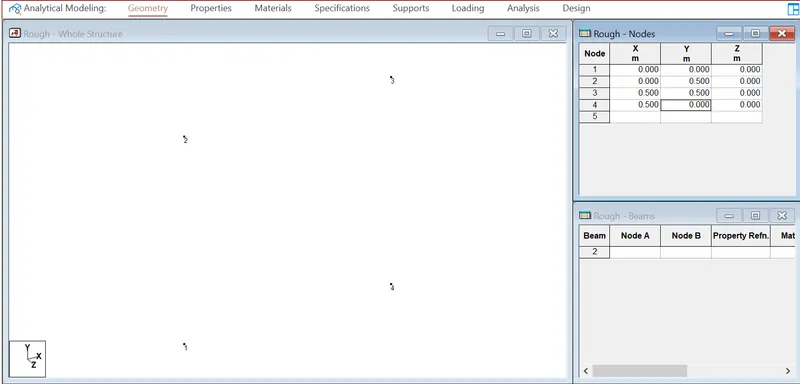
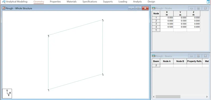
Now click on add plate to create plate between nodes

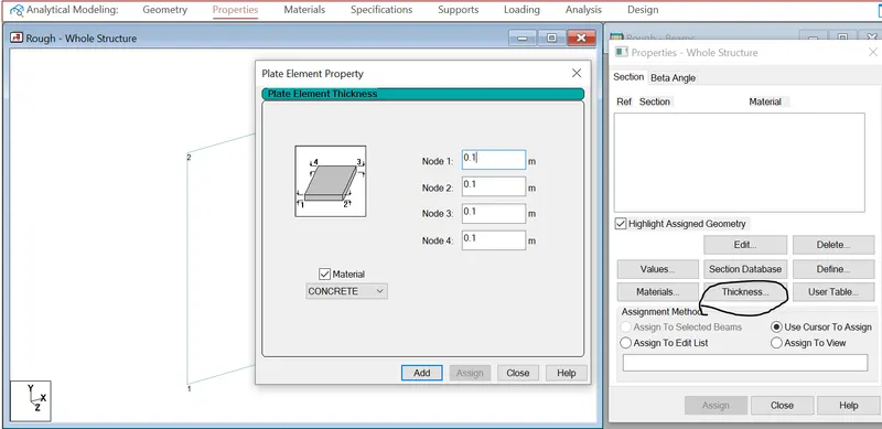
Now assigning property to the plate
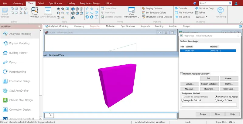
In this way plate is created
3) What are SLS combinations used for live loads, with respect to impact factor and how the moments for the section are derived?
Ans. As per IRC 6 SLS combination factor for live load is 1 which has to be increased by 10% for PSC, therefore factor becomes 1.1. Impact factor CDA as per IRS bridge rules will be 0.15+8/(6+L).
For deriving moments for the section, a line model is created in Staad having longitudinal dimension of the girder
4) What is prestressing in girders? What are advantages of Prestressed girders in a metro project.
Ans. Pre-stressed concrete is a form of concrete where initial compression is given in the concrete before applying the external load so that stress from external loads is counteracted in the desired way during the service period. This initial compression is introduced by high-strength steel wire or alloys (called ‘tendons’) located in the concrete section as shown in figure below.
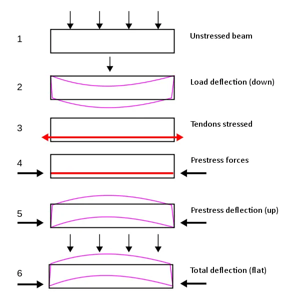
We know, concrete is good at compression but very weak in tension. And so we see after external loading, in the bottom part of concrete, a tension zone occurred. So, it tries to be elongated, and guess what? It cracks. This is why we add some steel bars at the bottom section so that it can resist most of the tension and save concrete from cracking. This is our traditional RC structure. But what about some megastructures with larger beam spans where external loading is very high.
In the way of a traditional RC structure, for these larger beam spans, we should provide a larger depth which is often too much that, for a bridge over a river, there will be not enough space under the bridge for ships to pass it. Here comes this new concept--- Pre-stressed concrete. The concept of prestressed concrete is not so difficult. In fact, the practice of prestressing things is very older in our day-to-day life. Imagine a barrel made of wooden staves and metal bands.
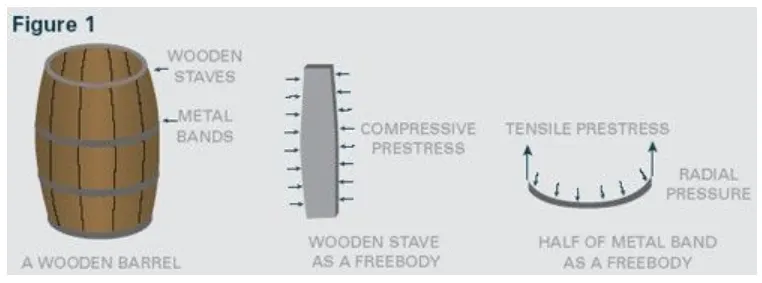
The basic principle of prestressing was applied to construction, perhaps centuries ago, when ropes or metal bands were wound around the wooden staves to form a barrel (see Figure 1). When the bands were tightened, they were under tensile prestress, which in turn created compressive prestress between the staves and enabled them to resist hoop tension produced by internal liquid pressure. In other words, the bands and the staves were prestressed before they were subjected to any service loads.
Like this, in prestressed concrete, initial compression is given to be balanced by future loading that will create tension.
How does Pre-Stressed Concrete Work?
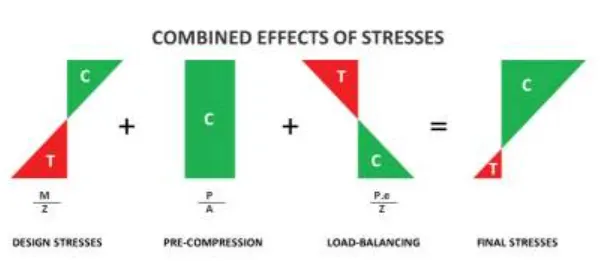
So by now, I have had our concept. We have learned why and when we should use prestressed concrete. So, how does it work? In the real life, high tensile strength steel wires are inserted into the beam section and they are stretched and anchored, then released. Now the steel tendon wants to gain its original length and tensile stresses are transformed into compressive stress in the concrete. Now after loading there are two kinds of forces on the beam,
- Internal prestressing force
- External forces (Dead load, Live load, etc.)
Which must counteract each other. Observing the moment diagram, we will find something like this
- It is a light weight section hence can be built on a single go and can be easily launched on piers.
- It is a slender section, also light weight therefore foundation size gets optimized thereby saving the economy.
- Since it's light weight seismic force also reduces for design.
- As it I'd light weight it can be erected also easily.
5) Explain about prestressing losses? What are different type of prestressing losses and mention the significance of the prestressing losses?
Ans. Prestressing is applying compressive stress to concrete to mitigate tensile strains caused by a load. Losses in prestress are the slow lowering of the induced compressive stress in a prestressed part due to various factors
There is a reduction in prestressing force from the recorded value in the jack gauge even during prestressing of the tendons and prestress transfer to the concrete member. The various reductions of the prestressing force are termed as the losses in prestressing.
The losses are majorly classified into two groups, immediate (Short term) and time-dependent (Long term). The immediate losses occur when the tendons are prestressed and prestress is transferred to the concrete part, and time-dependent occurs when the prestress members are used or in its service life. The various types of losses are listed below.
Immediate (Short term)
- Losses due to friction.
- Losses due to elastic shortening of concrete.
- Losses due to anchorage slip.
Time-Dependent Losses (Long term)
- Losses due to creep of concrete.
- Losses due to shrinkage of concrete.
- Losses due to creep or relaxation of steel.
Pre-tensioning and post-tensioning are the two procedures for imparting prestressing to a concrete member. Pre-tensioning occurs before the concrete is cast, while post-tensioning occurs after the concrete has hardened. Various forms of losses can occur depending on the prestressing technique.
Losses in Pre-tensioning
- Losses due to elastic shortening of concrete.
- Losses due to creep or relaxation of steel.
- Losses due to shrinkage of concrete.
- Losses due to creep of concrete.
Losses in Post-tensioning
- Losses due to friction.
- Losses due to creep or relaxation of steel.
- Losses due to shrinkage of concrete.
- Losses due to creep of concrete.
- Losses due to anchorage slip.
When all the bars are tensioned simultaneously, there are no losses owing to elastic shortening in the post-tensioning. However, if the bars are successfully tightened, prestress will be lost owing to elastic shortening.
Loss in Prestress Due to the Friction
During stretching a curved tendon in a post-tensioned part, friction is formed at the interface of concrete and steel. There is a reduction in prestress along with the member from the stretched end. The stretching must also overcome the tendon's wobbling in addition to friction. The change in location of the tendon along the duct is referred to as the wobble. Friction and wobbling losses are grouped together under friction. Frictional losses do not arise in pre-tensioned members since the tendon is not concretely tensioned in pre-tensioned members.
Loss of prestress due to the friction (σf)= (P0/A)(Kw X+αμ)
where,
- Kw= wobbles friction loss
- X = L: When jacking from one end
- X = L/2: when jacking from both the ends
- α=Angle of a tendon (Radian)
- μ=Coefficient of friction
Losses in Prestress Due to Anchored Slip
Anchorage is a component that is used to attach the tendons to the concrete while terminating them. When the stressing process is over, the major role of anchorage is to transfer the stressing force to the concrete. Tendons are provided inside the ducts of a precast concrete member in the case of a post-tensioning system. To transfer the stressing force to the concrete, anchoring is supplied at both ends of the tendon. If the anchorage moves from its original position, the tendons loosen, resulting in prestress loss. The loss of stress due to anchorage slip does not occur in the pre-tensioned concrete. The tendons are monolithically implanted in the concrete when pre-tensioning.
The loss due to anchorage slip (σa)= (Δl/l)Es
where,
- Δl = anchorage slip in mm
- l = Length of cable in mm
- Es= Young's modulus of steel (N/mm2)
Losses in Prestress Due to Elastic Shortening of Concrete
The loss is only encountered in the Pre-tension member; when the tendons are cut, and the prestressing force is transferred to the member, the concrete undergoes immediate shortening due to the prestress. In addition, the tendon shortens by the same amount. This results in a loss of prestress. Whereas if there is only one tendon, there is no loss because the applied prestress is recorded in the Post-tensioned member after the elastic shortening of the member. When more than one tendon is stretched sequentially, a tendon is lost during the successive stretching of the other tendons.
Loss of prestress due to elastic shortening of concrete (σe)= mσc
where:
- m = Modular ratio
- σc= Stress in the concrete at the level of a steel tendon
Losses in Prestress Due to Creep of Concrete
Creep is the deformation that occurs over time due to a constant force. Prestress is a permanent force in prestressed concrete that causes compressive stress at the steel level. As a result, the member is under stress. Loss of prestress due to concrete creep occurs in both the pretension and post-tension member.
Loss of prestress due to creep of concrete (σcr)= θmσc
where,
- m = Modular ratio
- σc= stress in the concrete at the level of a steel tendon
- θ = Creep coefficient (depends on the age of loading)
|
Age of loading |
Creep Coefficient () |
|
7 days |
2.2 |
|
28 days |
1.6 |
|
1 year |
1.1 |
Losses in Prestress Due to Creep or Relaxation of Steel
Steel relaxation is described as a decrease in stress over time when under constant tension; due to the relaxation of steel, the pressure in the tendon is reduced with time. The stress loss due to relaxation depends on the types of steel, initial pressure, and temperature. Based on the observation, about 2 per cent loss occurs in pre-tensioned members, whereas about 3 per cent loss of stress occurs in post-tension members.
Losses in Prestress Due to Shrinkage of Concrete
The stress loss is aided by the shortening of tensioned wires caused by concrete shrinkage in prestressed members. In the case of pre-tensioned members, moist curing is usually used to keep them from shrinking until they are transferred. As a result, the total residual shrinkage strain in pre-tensioned members after prestress transfer will be greater than in post-tensioned members, where a portion of shrinkage will have already occurred at the time of stress transfer.
Loss in Pre-tensioned member
Strain due to shrinkage of concrete (εsh)= 0.0003
Stress due to shrinkage of concrete (σsh)= 0.0003Es
(σsh)= 0.0003*2*105
(σsh)= 60 MPa
Loss of Post-tensioned member
Strain due to shrinkage of concrete (εsh)= 0.0002/[ln(T+2)]
T= time of prestressing in days (normally 28 days)
Strain due to shrinkage of concrete (εsh)= 0.0002/ln(28+2)
(εsh)= 5.88 * 10-5
Stress due to shrinkage of concrete (σsh)= 5.88 * 10-5*(Es)
(σsh)= 5.88 * 10-5* 2 * 105
(σsh)= 12 MPa
Therefore the loss of stress due to shrinkage is more in pre-tension members.
Note: Total Losses in prestressed concrete are listed in the table below.
|
Types of loss |
Pretensioned (Percentage) |
Post-tensioned (Percentage) |
|
Elastic shortening of concrete |
3 |
1 |
|
Shrinkage of concrete |
7 |
6 |
|
Creep of concrete |
6 |
5 |
|
Relaxation of steel |
2 |
3 |
|
Total Loss |
18 |
15 |
The total loss in the pre-tensioned member is more than the total loss in the post-tensioned member; it differs mainly due to the elastic shortening of concrete.
6) How a girder is being prestressed while fabrication? Explain the components/materials used during the prestressing?
Ans.
In the fabrication stage below, we can see the highly tensioned steel “strands” or wire cables, which are the very long horizontal lines at top and bottom and diagonally across the middle, all extending from one end of the future beam to the other. The green vertical steel elements, curved and shaped at the top and bottom, are the traditional “rebars” or reinforcing steel, creating the steel cage that gives shape and added strength to the finished beam.
The steel strands are stretched to create an extremely high state of tension or stress and anchored in the large yellow bulkhead at the end of the beam, seen in the photo below. When stretched and stressed, the strands will become 20 to 30 inches longer. You’ll see the cut ends of the elongated strands extending out to the right of the yellow bulkhead.
The long prestressing and fabricating bed allows more than one beam to be made at the same time, end to end in the photo below. For economy and efficiency, the steel strands are pulled and tensioned through two beams at once.
After all the steel is in place, yellow metal forms are positioned on both sides of the steel cages (below) for the concrete mix. The metal forms will create the traditional I-beam shape of the finished prestressed concrete beam.
With the yellow metal forms in position around the steel cage, concrete is poured into the tops of the forms in the photo below.
When the forms are removed, the finished concrete beam emerges, displaying its iconic I-beam shape below. It is now “prestressed pretensioned,” because the concrete has formed and hardened around the tensioned steel strands. At that point, the strands are cut at the ends of the beams. The stretched steel strand wants to return to its original, shorter length, but the concrete hardened around it prevents it from returning back. The force in the strand is induced to the concrete to put the concrete beam in in a state of high compression as the stress is incorporated into the whole beam.
This beam is now ready to be hauled to a bridge construction site, below.
Some prestressed concrete beams are huge!
The weight of the larger beams can exceed 100 tons and be as long as 180 feet. Special trucks with multiple axles may be required to distribute the load into the roadways. And a “steerable” trailer in the rear might be needed to get around corners.
7) How are stresses in the girder calculated with the resultant prestressing losses?
Ans. Lets assume an example for this,
Assume No.of strands (n) = 72
Prestressing force applied (P) = 0.765fpu x As x n x (1-loss) / 1000 kN
fpu = Nominal ultimate stress = 1860 MPa
Maximum jacking stress = 0.765 fpu = 0.765 x 1860 = 1422.9 MPa
As = Area of strand = 140mm2
Assume loss of 17.5%
Prestressing force (P) = 11832.8 kN
Stress @ bottom of girder = Compressive stress due to tendons - tensile stress due to external loading
= ( P/A + P.e/Z) - (M/Z)
Z = I/y = 1.24m3
A = Sectional Area of girder = 2.1735 m2
P = 11832.8 kN as calculated above
e = centre of gravity of girder section @ bottom of girder- centre of gravity of tendon @ bottom of girder = 0.454m
M = moment of SLS combination from longitudinal analysis for DL & LL combination = 10628.58 kNm
Therefore, Stress @ bottom of girder = 1.607 n/mm2 (Since the resultant stress is positive it is compressive, as to avoid tension we are providing tendons)
8) Explain the step wise procedure of transverse analysis of open web structure of U girders in STAAD pro along with how the vehicle parameters and loadings are fed in the STAAD software.
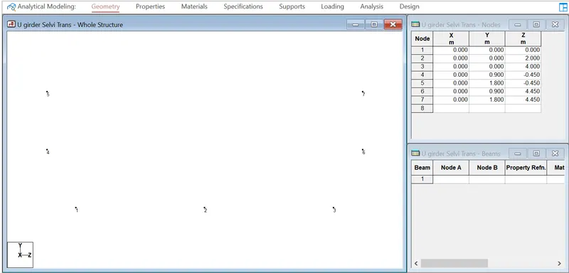
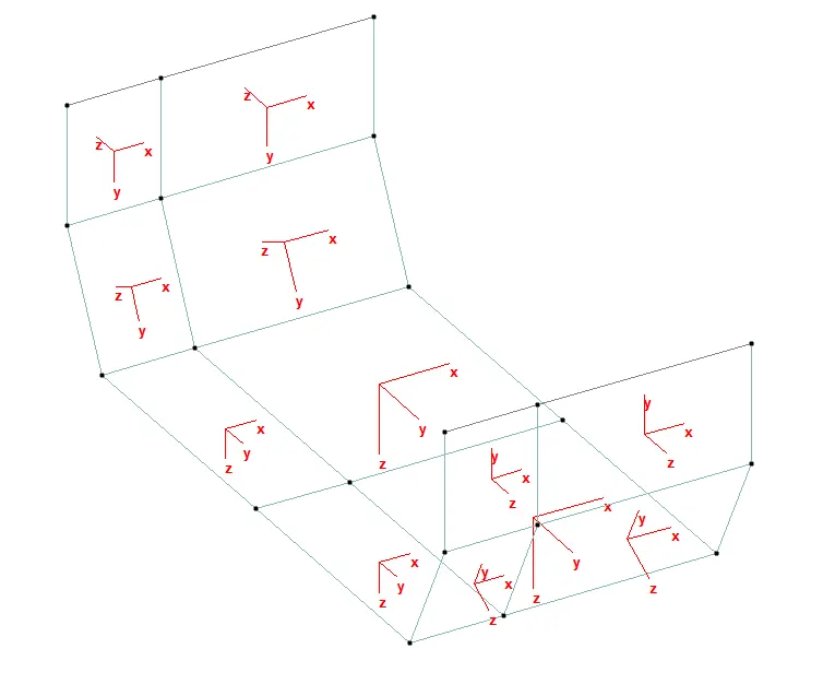
Ans. For transverse analysis whole structure has to be modelled & designed as per FEM. So we will first create coordinates for U girder. having slab width of 4m and height of web is 1.8m.
Dimensions in staad will be c/l dimensions of the girder.
Nodes for single section is as shown.
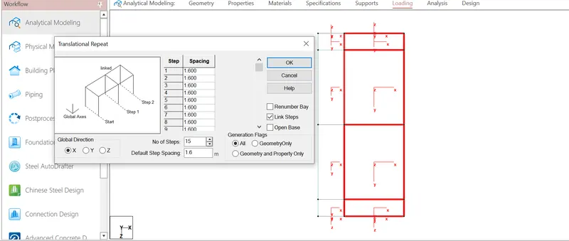
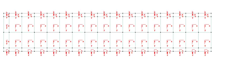
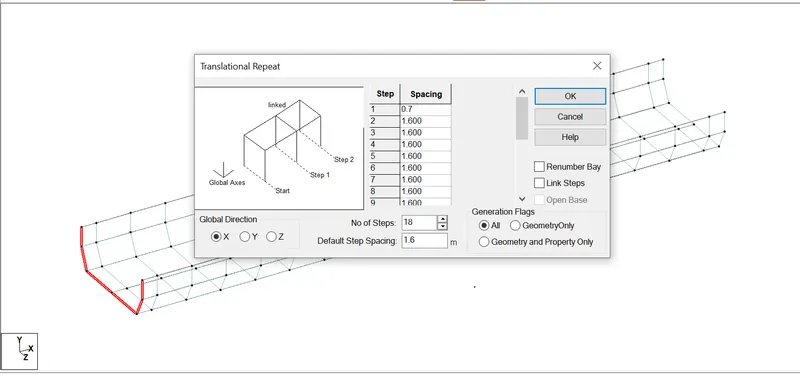
Now we will translate this section for the whole span.
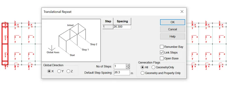
First translation will be at the support section which is at 0.7m from the end
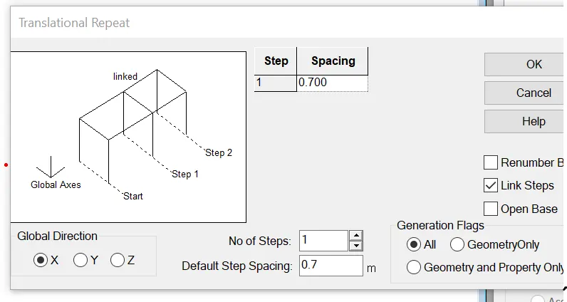
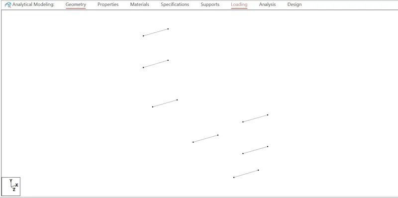
Now total length of girder is 27m, support overhang is 0.7m at both ends, therefore c/c of supports is 27-0.7-0.7=25.6m
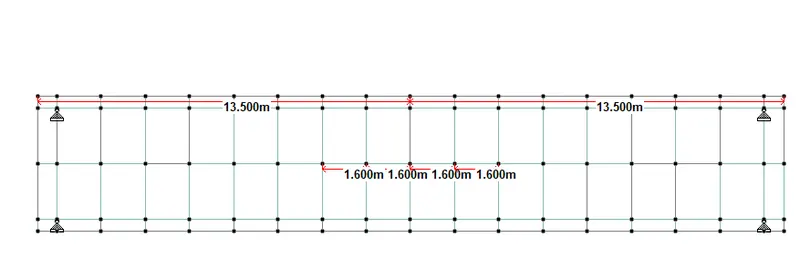
Now this 25.6m will be divided into 16 equal parts of 1.6m for translation
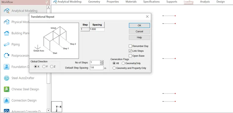
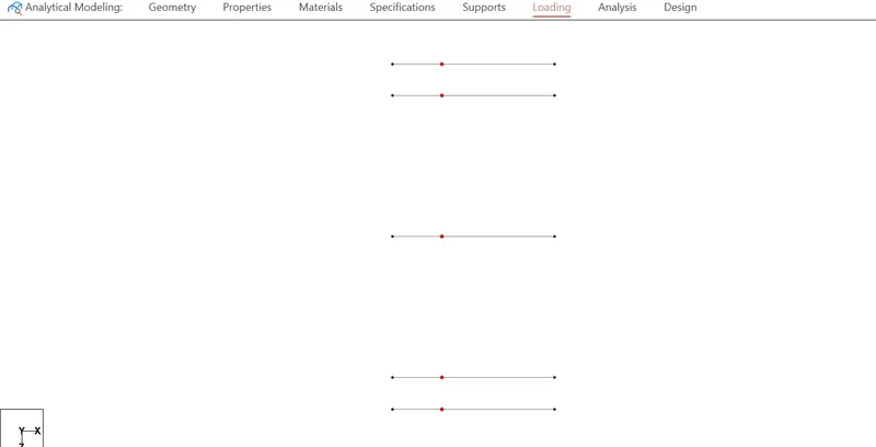
Now we will create the slab & web as plate sections in clockwise direction for its local axis to be in same direction
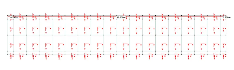
Now we have to add beams to the girder for load application
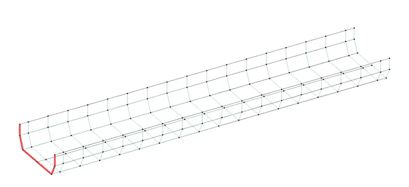
Now translate this beam with 1st beam & last beam at 0.7m & middle beams at 1.6m as per geometry
Now we will break the horizontal beams with respect to nodes and then delete the duplicate beams as we have linked the structure while creating beams and while creating sectional beams.
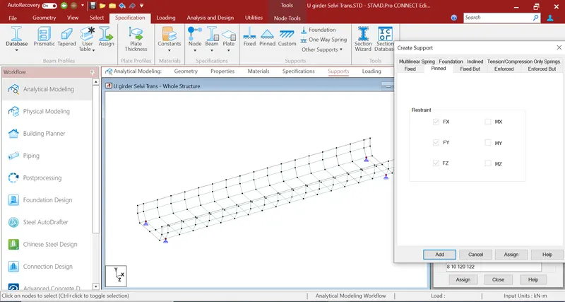
Now we will add supports at the ends
Now we will create property for the plate sections
For base slab
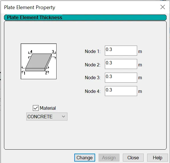
For straight web
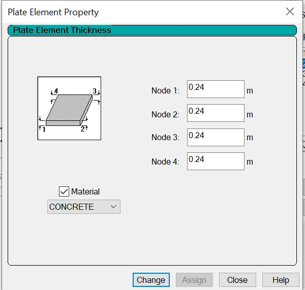
for innclined web left side
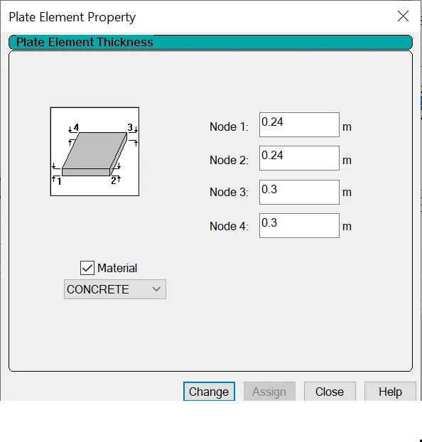
for inclined web right side
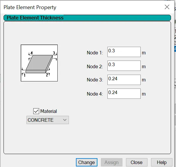
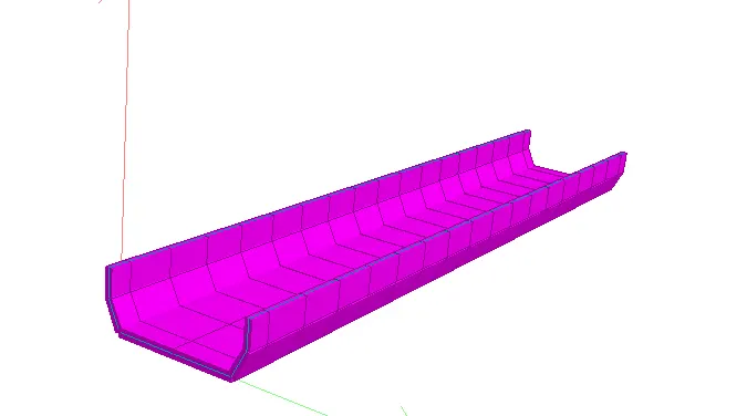
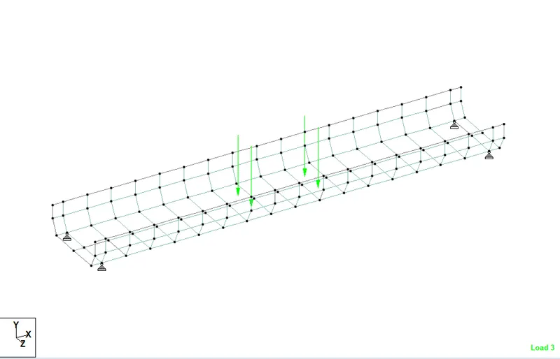
3D view of the girder
Now we will add loading to the girder
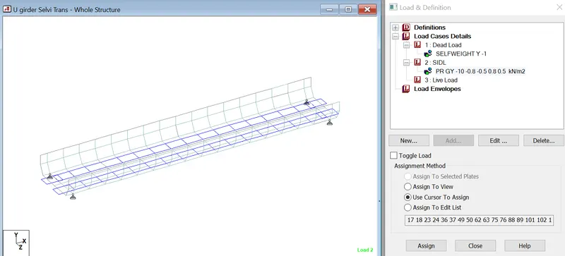
Dead load will be added as self weight with factor Y-1
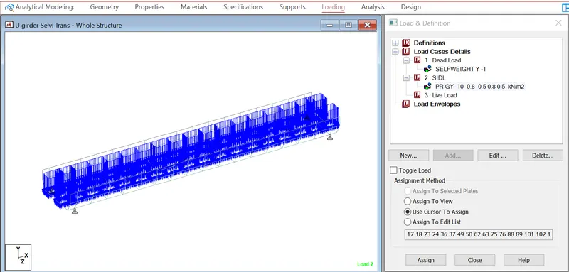
SIDL is applied as follows, it includes all the track, rail pad, plates attached etc loading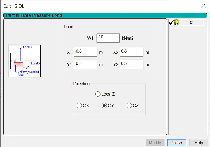
Since each plate is 1.6m in length X coordinates is given as -0.8 to 0.8m and since width is 1m Y coordinate is given as -0.5 to 0.5m.
Live load analysis shall not be done by moving vehicle as in longitudinal analysis it has been already done. So we take critical points from longitudinal analysis and apply vehicle load here.
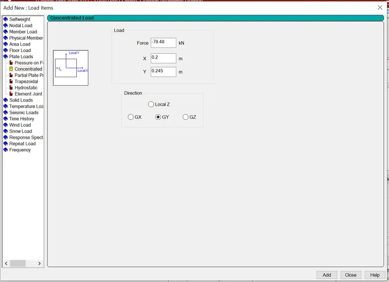
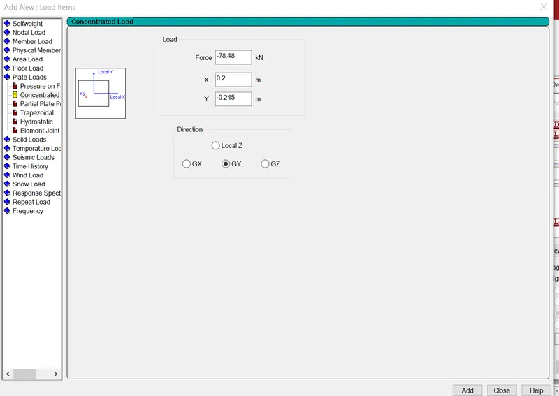
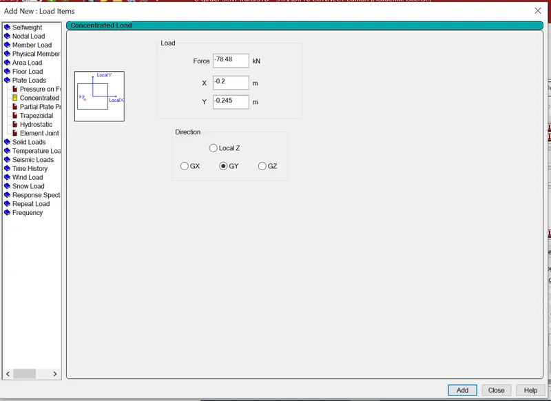
Axle load of metro is 16t, wheel load will be 16/2 = 8t = 78.48kN.
Wheels are spaced at 1.51m (Trans direction)
Metro train arrangement
| 16T | 156.96 | kN |
| Load | Distance | |
| 156.96 | ||
| 156.96 | 2.3 | 1st Bogie |
| 156.96 | 12.4 | |
| 156.96 | 2.3 | |
| 156.96 | 4.4 | Gap |
| 156.96 | 2.3 | 2nd Bogie |
| 156.96 | 12.4 | |
| 156.96 | 2.3 |
Maximum loading is observed when the train arrangement is in centre
4.4/2 = 2.2 on each side from centre of plate
One plate length = 1.6m , so 1.6+ 0.6 from next plate
centre of next plate is 1.6/2=0.8m
So 0.8-0.6=0.2m will be X coordinate
In Y direction distance of wheel is 1.51m
1.51/2=0.755m
Since plate width is 1m , Y coordinate = 1-0.755=0.245m
Left part of cross section or top part of top view
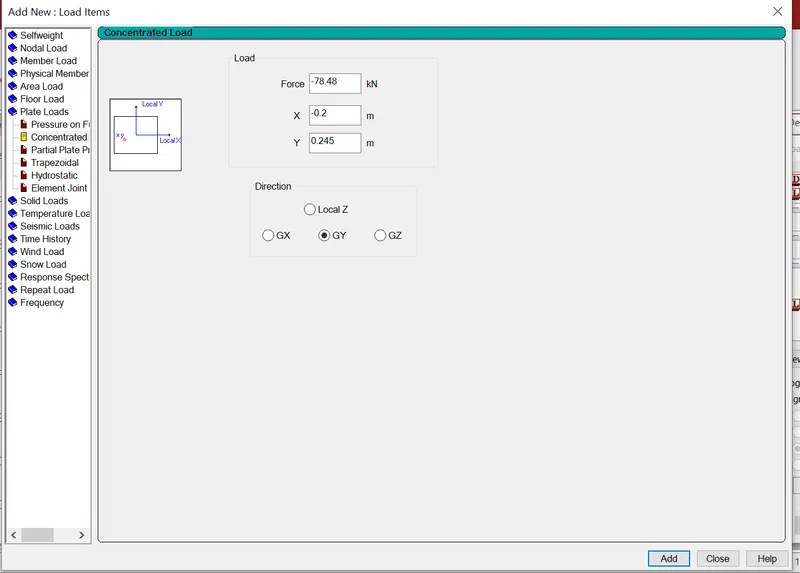
Right Part of cross section, bottom of top view
Now after adding loading, load combination is created
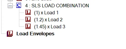
for critical SLS combination as per IRC CBC, factor for DL is 1, SIDL is 1.2 and for live load factor is 1.1 plus we need to multiply live load with impact factor.
Impact factor CDA as per IRS bridge rules will be 0.15+8/(6+L) = 0.15+8/(6+25.6) = 0.403.
Now this CDA is for broad guage as per IRS we have to calculate it for metro.
Speed for metro is 90km/hr whereas for Broadguage it is 116 km/hr
Therefore impact factor will be 0.403x(90/116)=0.313
Impact factor x Live load factor = 1.313 x 1.1 = 1.45 = factor for live load in SLS combination
After Analysis, as we know this is transverse analysis so we need to see bending along Global Z direction in STaad which will be Local Y for plate.
Max My from table is
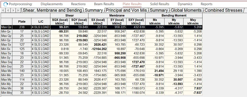
Plate 114 has maximum My 30kNm, this the force for only at centre of plate
for detail summary below summary is referred
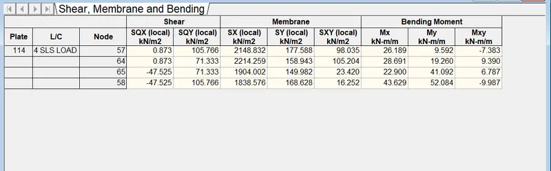
Based on this reinforcement and stress check is done
9)How is the longitudinal analysis of open web structure of U girder performed, final design bending moments and axial stresses are extracted? Explain the software procedure for extracting the same.
Ans. First we prepare a line model of 27m for longitudinal analysis with dimensions shown below,
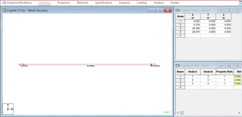
expansion gap of 0.025 is left on both sides at then at 0.675m distance pin support is assigned on both ends
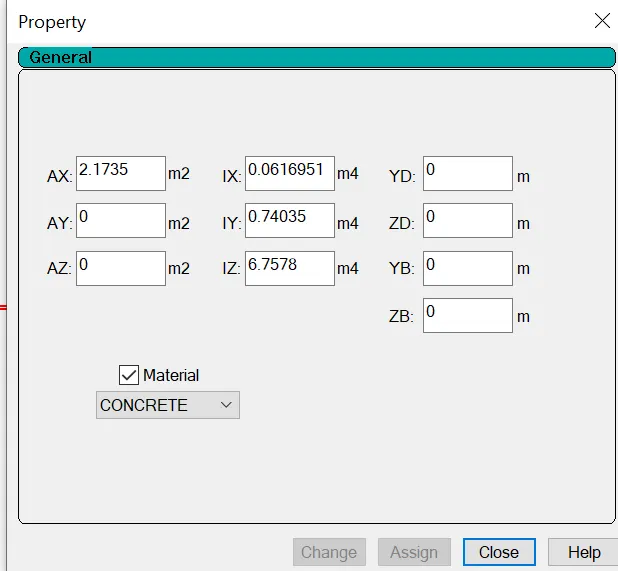
Property as extracted from cad software is put as prismatic general for beam
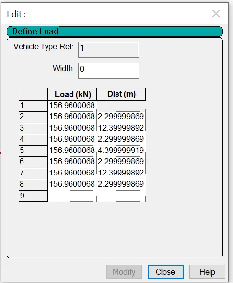
Now as this is a single line model, live load vehicle width is not considered and axle load is applied as shown
Metro load is 16t which is 156.96 kN and since span is 27m 2 bogies are considered with 4.4m gap
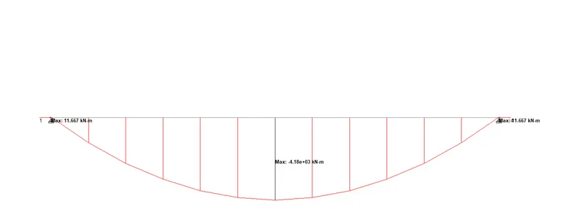
DL is added as selfweight with factor Y = -1 as we have given sectional properties to the structure
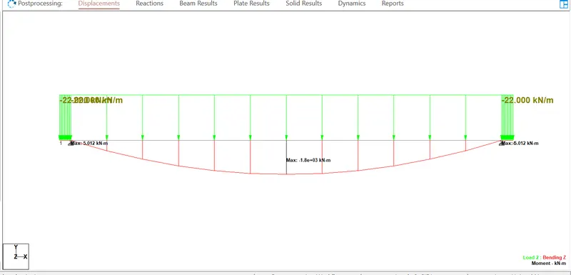
SIDL of -22kN/m is applied which includes all the track and rail loads
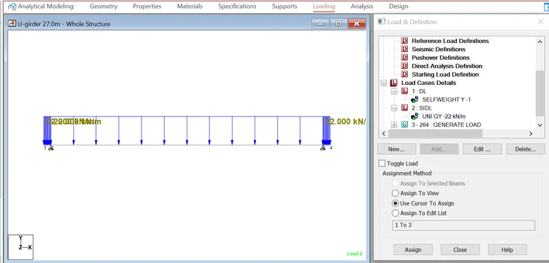
Now for Live load vehicle generation is done
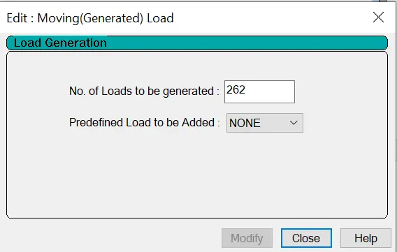
Length of metro train+ Span = 2.3+12.4+2.3+4.4+2.3+12.4+2.3+27=65.4m
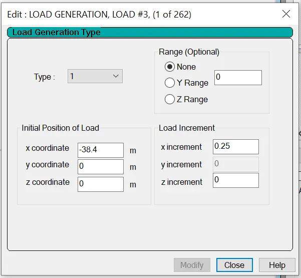
Increment considered = 0.25m
Therefore no.of loads to be generated = 65.4/0.25 = 261.6 hence considering 262no of load generation
x coordinate = length of train = 38.4m
Now model is analysed
Result is extracted
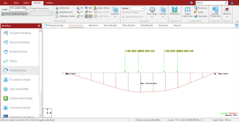
Maximum bending moment for live load
Bending moment for SIDL
bending moment for DL
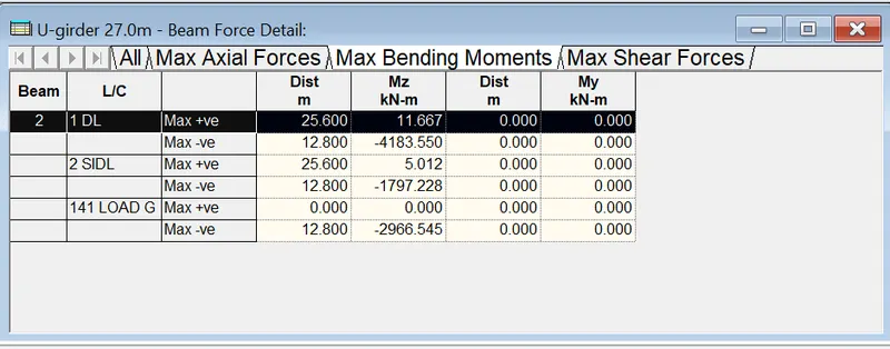
SLS LOAD COMBINATION = DL+1.2*SIDL+1.1*LL*I
I=Impact factor
Impact factor CDA as per IRS bridge rules will be 0.15+8/(6+L) = 0.15+8/(6+25.6) = 0.403.
Now this CDA is for broad guage as per IRS we have to calculate it for metro.
Speed for metro is 90km/hr whereas for Broadguage it is 116 km/hr
Therefore impact factor will be 0.403x(90/116)=0.313
Impact factor x Live load factor = 1.313 x 1.1 = 1.45 = factor for live load in SLS combination
Moment = 4183.55+1.2*1797.228+1.45*2966.545 = 10628.58 kNm
This moment is used for design