Challenge 2- Comparing the performance of three types of beams under bending load.
AIM: - COMPARING THE PERFORMANCE OF THREE TYPES OF BEAMS UNDER BENDING LOAD
SOLUTION:
Three beams of different cross-sectional areas are to be modeled in Solidworks. Next, the beam models are to be supplied with necessary boundary conditions, the loading conditions, and the meshing conditions.
Finally performing the simulation for all the three beams and comparing the resulting Stress, Strain, and Displacement in all three beams and based on that selecting the best one.
Note: 3D simulation is done to obtain more accurate results.
The three cross-sections of the beam sketched in Solidworks are shown below:
1. RECTANGULAR CROSS-SECTION:
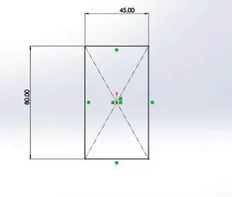
- Rectangle of cross-sectional dimensions of 80 mm x 45 mm.
- The beam will be created after extruding this for 400 mm length normal to the cross-section area.
- The beam is a Cantilever Beam with one end of the beam being fixed and the other being free. This will be done through the following steps:
- Open Solidworks Simulation Add-in. Next, click on ‘New Study’, it will bring the Property Manager asks the type of analysis that should be performed on the given geometry.
- Here, the ‘Static’ analysis will be chosen since the loading condition is gradually applied load condition.
- Select the ‘Static’ option and then click on the green check to move further.
- The next step in the analysis is to assign the material to the beam. Select the material ALLOY STEEL , press Apply, and then close. On successfully applying the material to the beam will look like this:
- The next step is to turn this beam into a Cantilever Beam. This is done by right-clicking on ‘Fixtures’ and then selecting the ‘Fixed Geometry’ option. After doing this, the property manager will ask to select the face which is needed to be fixed. Then, after selecting the desired surface the beam.
- The next step is to add the external load to the beam. This is done by right-clicking on the option ‘External Loads’ and selecting the option ‘Force’. After that, the Property Manager will ask to select the face or edge on which the force must act. Now select the Top Face of the beam by clicking on it. Now give the magnitude of the force, equal to 1500 N, then click on the green check to finish. Now the beam will look like this:
Now, the beam is required to mesh. The meshing is done by right-clicking the option ‘Mesh’ and then select mesh and run the simulation.
Following results are obtained for
Stress:
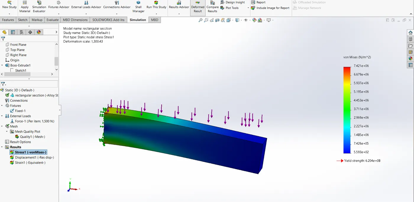
Max stress value obtained is 7.42Mpa
Displacement:
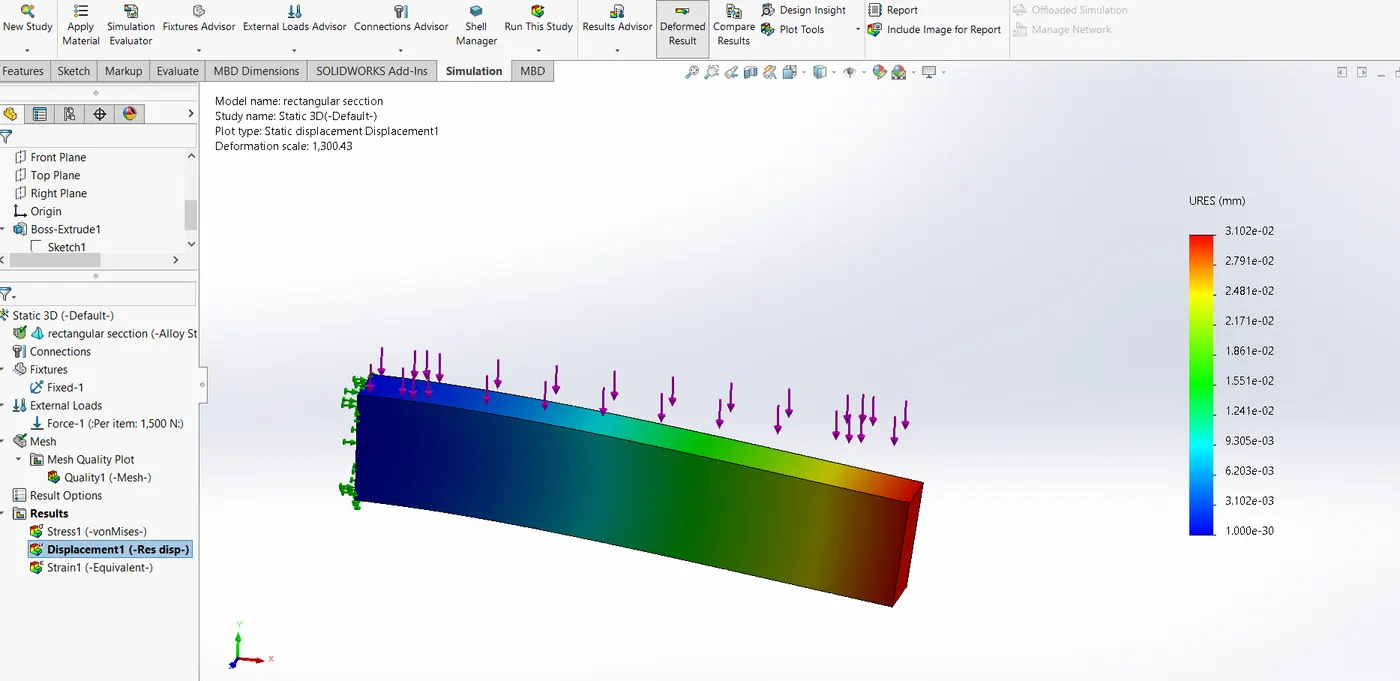
Deflection at free end is 0.03102mm
Strain:
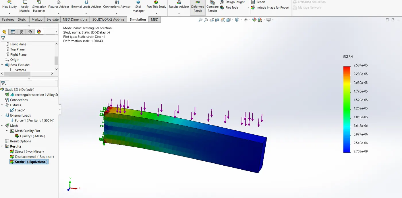
Max. strain is 2.537*10-5
2. I CROSS-SECTION:
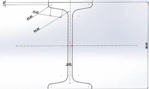
- I of cross-sectional dimensions of 80 mm x 40 mm.
- The beam will be created after extruding this for 400 mm length normal to the cross-section area.
- The beam is a Cantilever Beam with one end of the beam being fixed and the other being free. This will be done through the following steps:
- Open Solidworks Simulation Add-in. Next, click on ‘New Study’, it will bring the Property Manager asks the type of analysis that should be performed on the given geometry.
- Here, the ‘Static’ analysis will be chosen since the loading condition is gradually applied load condition.
- Select the ‘Static’ option and then click on the green check to move further.
- The next step in the analysis is to assign the material to the beam. Select the material ALLOY STEEL , press Apply, and then close. On successfully applying the material to the beam will look like this:
- The next step is to turn this beam into a Cantilever Beam. This is done by right-clicking on ‘Fixtures’ and then selecting the ‘Fixed Geometry’ option. After doing this, the property manager will ask to select the face which is needed to be fixed. Then, after selecting the desired surface the beam.
- The next step is to add the external load to the beam. This is done by right-clicking on the option ‘External Loads’ and selecting the option ‘Force’. After that, the Property Manager will ask to select the face or edge on which the force must act. Now select the Top Face of the beam by clicking on it. Now give the magnitude of the force, equal to 1500 N, then click on the green check to finish. Now the beam will look like this:
Now, the beam is required to mesh. The meshing is done by right-clicking the option ‘Mesh’ and then select mesh and run the simulation.
Following results are obtained for
Stress:
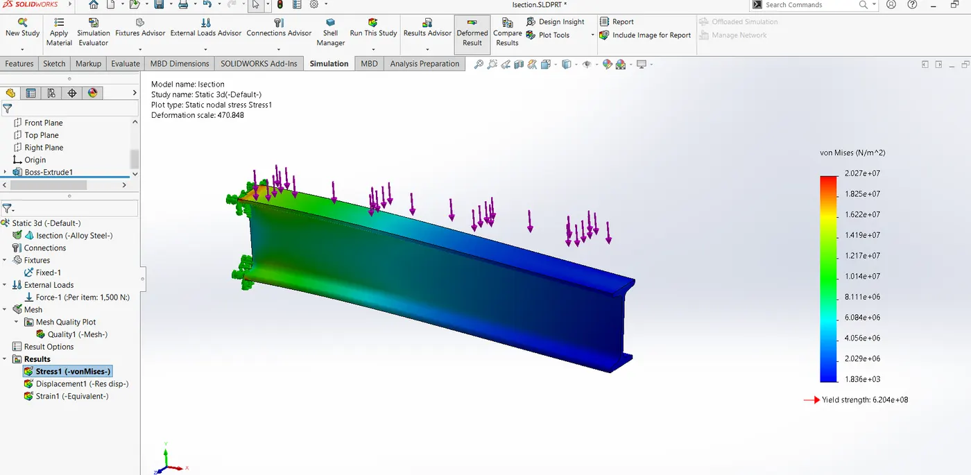
Max stress value obtained is 20.27 Mpa
Displacement:
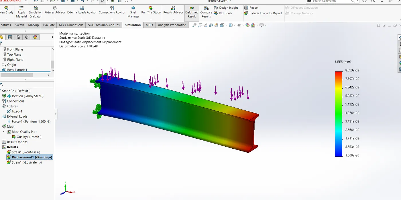
Deflection at free end is 0.08553mm
Strain:
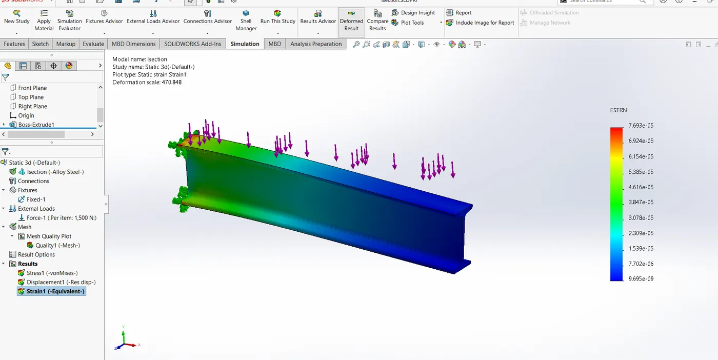
Max. strain is 7.693*10-5
3. C CROSS-SECTION:
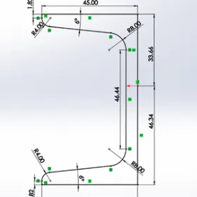
- C of cross-sectional dimensions of 80 mm x 45 mm.
- The beam will be created after extruding this for 400 mm length normal to the cross-section area.
- The beam is a Cantilever Beam with one end of the beam being fixed and the other being free. This will be done through the following steps:
- Open Solidworks Simulation Add-in. Next, click on ‘New Study’, it will bring the Property Manager asks the type of analysis that should be performed on the given geometry.
- Here, the ‘Static’ analysis will be chosen since the loading condition is gradually applied load condition.
- Select the ‘Static’ option and then click on the green check to move further.
- The next step in the analysis is to assign the material to the beam. Select the material ALLOY STEEL , press Apply, and then close. On successfully applying the material to the beam will look like this:
- The next step is to turn this beam into a Cantilever Beam. This is done by right-clicking on ‘Fixtures’ and then selecting the ‘Fixed Geometry’ option. After doing this, the property manager will ask to select the face which is needed to be fixed. Then, after selecting the desired surface the beam.
- The next step is to add the external load to the beam. This is done by right-clicking on the option ‘External Loads’ and selecting the option ‘Force’. After that, the Property Manager will ask to select the face or edge on which the force must act. Now select the Top Face of the beam by clicking on it. Now give the magnitude of the force, equal to 1500 N, then click on the green check to finish. Now the beam will look like this:
Now, the beam is required to mesh. The meshing is done by right-clicking the option ‘Mesh’ and then select mesh and run the simulation.
Following results are obtained for
Stress:
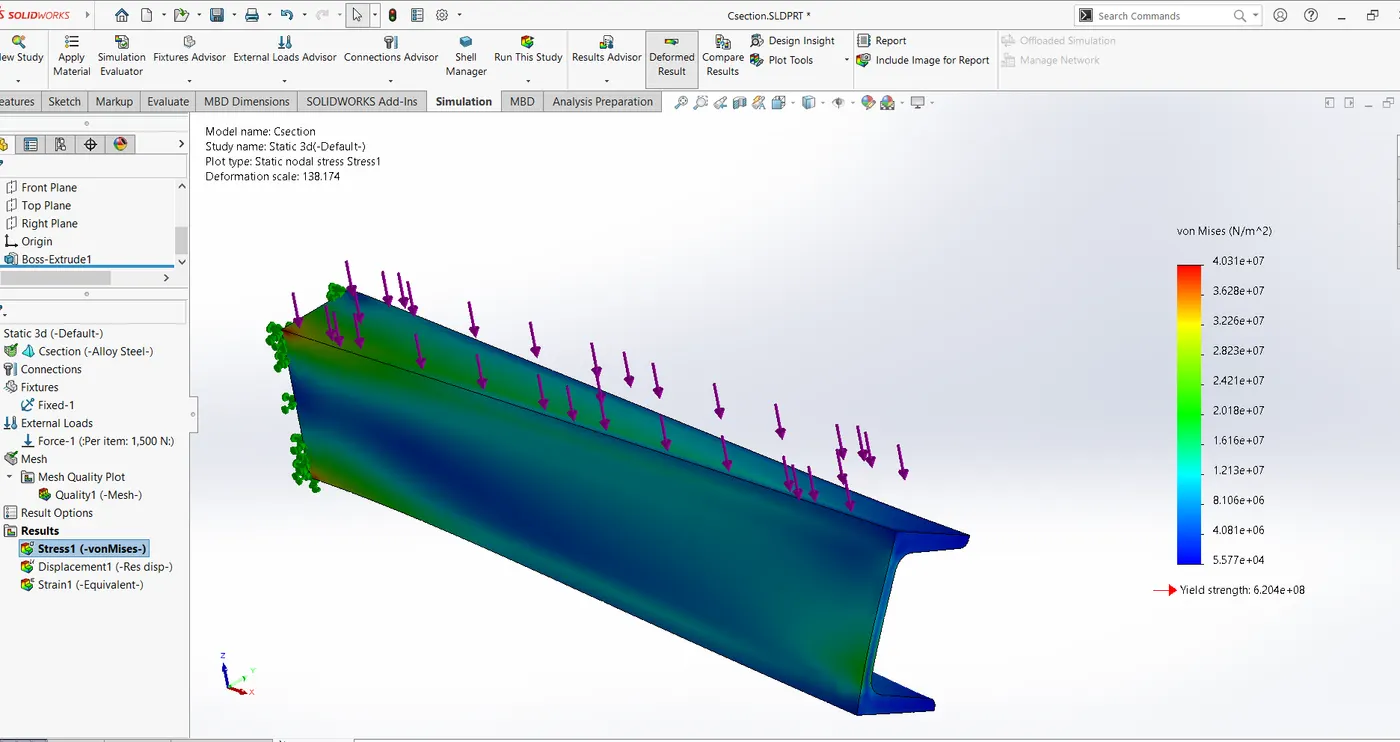
Max stress value obtained is 40.31 Mpa
Displacement:
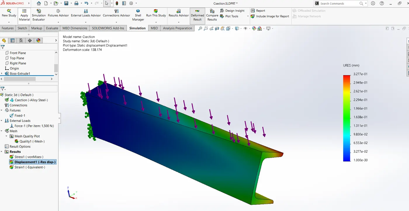
Deflection at free end is 0.08553mm
Strain:
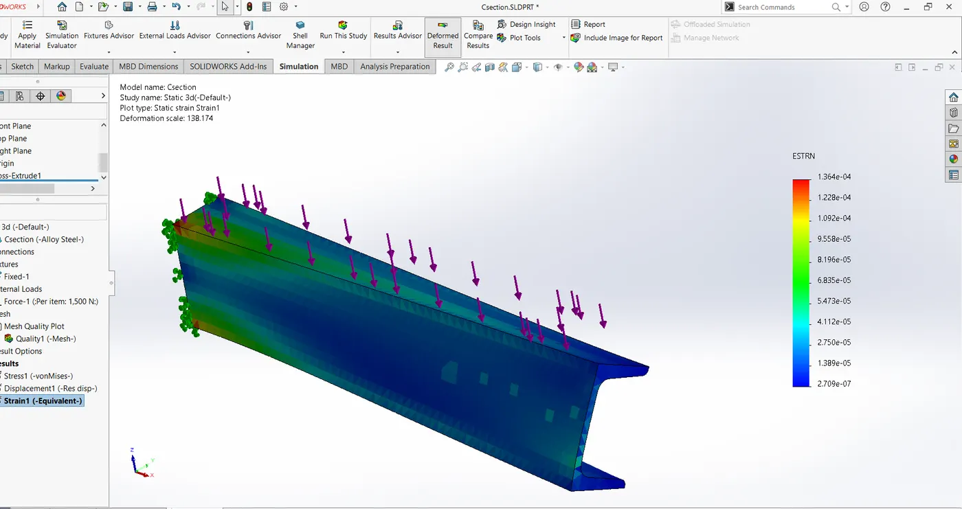
Max. strain is 1.364*10-4
CONCLUSION:
| STRESS (MPa) | STRAIN | DISPLACEMENT (mm) | |
| Rectangular | 7.42 | 0.03102mm | 2.537*10-5 |
| I-Section | 20.27 | 0.08553mm | 7.693*10-5 |
| C-Section |
40.31 |
0.0855 | 1.364*10-4 |
The load acting on all the beams is the same (1500 N), but due to the different cross-sections of each beam, the stress-induced are different for different beams.
The maximum stress is seen to be acting in the C-Section beam So it can be said that the C-Section Beam is worst loaded.
The stress and strain in rectangular section is less than other two. It should be preferred than others but
In general, the I-section beam is preferred. This is because both sections will bear the load but the I-section beam consumes lesser material because of lesser cross sectional area and give satisfactory results. So, I-Section Beams are more economical to use.