CENTRIFUGAL PUMP DESIGN AND ANALYSIS
1. Objective:-
i. Create a 3D model of a Simple Centrifugal Pump.
ii. Show the Performance diagram.
iii. Obtain the relationship between Pressure ratio and mass flow rate and explain the results.
2. Basic:-
2.1 Centrifugal Pump:-
The Hydraulics Machines which convert the mechanical energy into hydraulic energy in the form of pressure by means of centrifugal force is called as Centrifugal Pump.
The centrifugal pump is a reserve of inward flow reaction turbine. it works on the principle of forced vortex motion. it has a high discharging capacity and can be used for lifting viscous liquids. Also, it is used for low head and high discharge delivery. it lifts the fluid or just boosts the pressure in a pipeline.
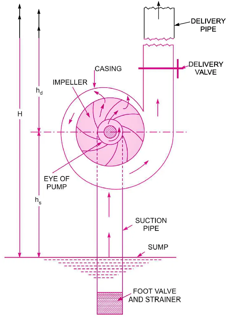
2.2 Components of Centrifugal pump:-
i. Impeller: It consists of a series of curved vanes. impeller mounted on the prime mover shaft. its function is to force the fluid into a rotating motion and shroud around the impeller is to direct the fluid through the impeller.
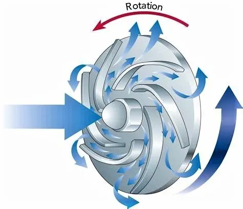
Note:- The pump gives maximum Efficiency when the vanes used are backwards curved.
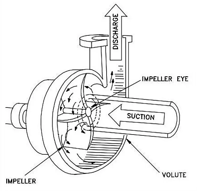
ii. Casing: The Pump Casing serves to seal off the inside of the pump to the atmosphere to prevents leakage and retain pressure. In the case of centrifugal pumps, casing surrounds the Rotor which transmits the energy to the fluid handled via the Impeller mounted on the rotating shaft.
Types of casing:
The commonly used casing is as follows
1. Volute Casing:
It surrounds the impeller having the spiral type in which area of flow increases gradually. the increase in the area of flow decreases the velocity of flow. the decrease in velocity increases the pressure of the water through casing. The efficiency of the pump increases slightly as a large amount of energy is lost due to the formation of eddies in this type of casing.
2. Vortex Casing: In this type of casing a circular chamber is introduced between the casing and the impeller. Hence it has more efficiency than the only involute casing.
3. Casing with guide Blades: Impellers is surrounded by a series of guide blades mounted on a ring which is known as a diffuser. the area of the guide vanes increases thus reducing the velocity of the flow through guide vanes and consequently increases the pressure of water.
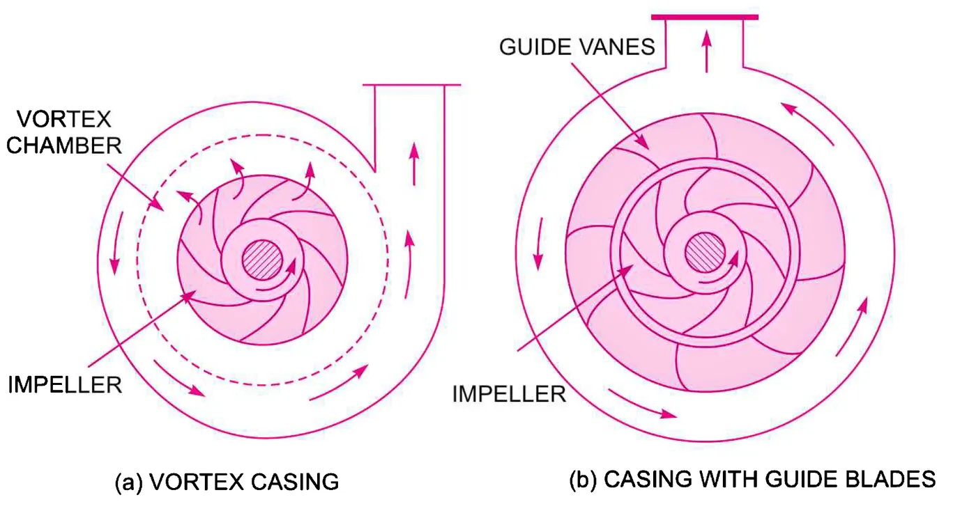
Note:- In Our case, we are taken the simple Centrifugal casing design related to the type three due to hardware limitations.
iii. Suction & Delivery Pipes: The suction pipe is connected with the inlet of the impeller and the other end is dipped into the sump of water. At the water end, it consists of the foot valve and strainer. The delivery pipe is a pipe connected at its lower end to the outlet of the pump and it delivers liquid to the desired height.
Note:- The Fluid Enters in the centrifugal pump via Axial Direction (i.e. from Centre) and Leaving from the Radial Direction.
iv. Foot valve: The foot valve is a one-way valve that opens in an upward direction.
Note:- Here we taken only those components of the centrifugal pump which is important and Going to play a major role in our Analysis.
3. Procedure:-
Step-1:- Designing Impeller.
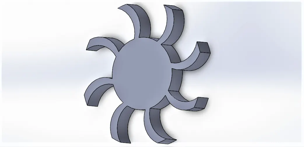
Step-2:- Designing Casing.
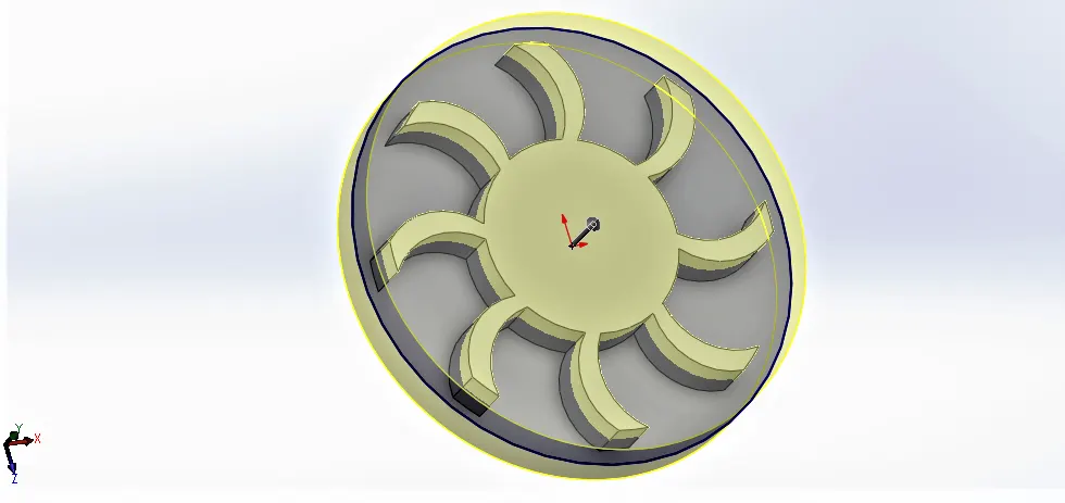
Step-3:- Designing the inlet and outlet of the pump and Using a combine option to combine the component.
Step-4:- Making New Region As shown below and Extruding it in such a way that it does not exceed the casing boundaries and also not intersect the impeller. i.e the new region is in between the casing and Impeller.|
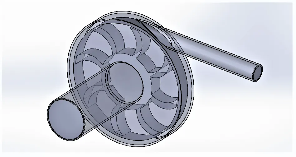
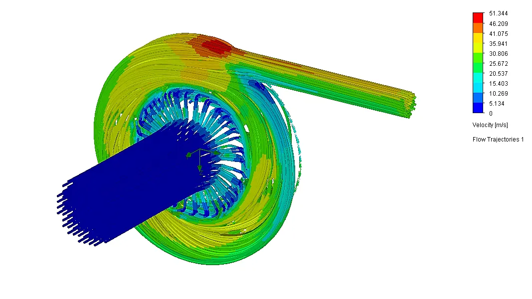
We are using region Because Meshing in Solidworks is not providing appropriate mesh. Hence it's not going to rotate the impeller or deform the mesh as the impeller rotates. We are going to use Approach called a moving reference frame and we create a zone i.e volume around the impeller. inside this volume, we basically add some additional terms in the governing equation. which basically simulates the effect of rotation. i.e we are simulating the effect of rotating by modifying the fundamental governing equation. The 3D Model of the Centrifugal pump as shown below.
Step-5:- Setting the flow simulation with the flow type, velocity, mesh size, and other parameters.
Step-6:- Setting Parametric study with the input and output parameters.
Step-7:- Run the calculation.
Note:- In the Designing of the 3D model of centrifugal pump we need to uncheck the merge option.
4. Simulation and Analysis:-
Simulation Parameters:
| Unit | : SI |
| Fluid Type | : Water |
| Rotation | : 1000 rad/s |
| Outlet Velocity | : from 10 to 30 m/s |
| Inlet Pressure | : 101325 pa |
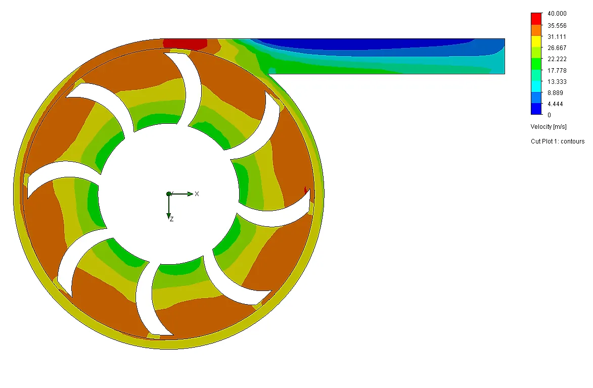
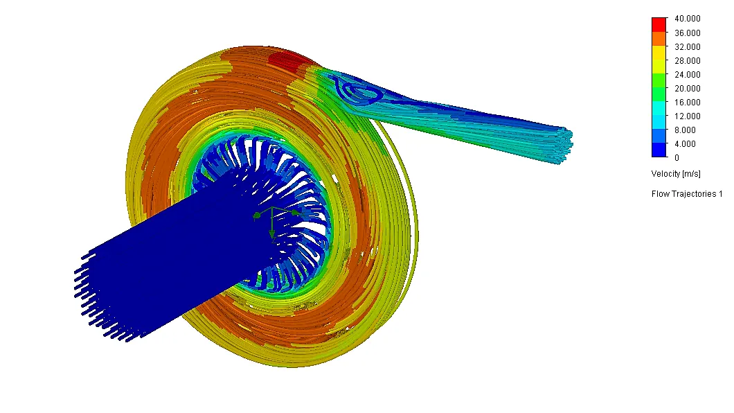
4.1 Design Point 1 (Velocity 10m/s):-
Cut plot:
 .
.
Flow Trajectories:
4.2 Design Point 2 (Velocity 15m/s):-
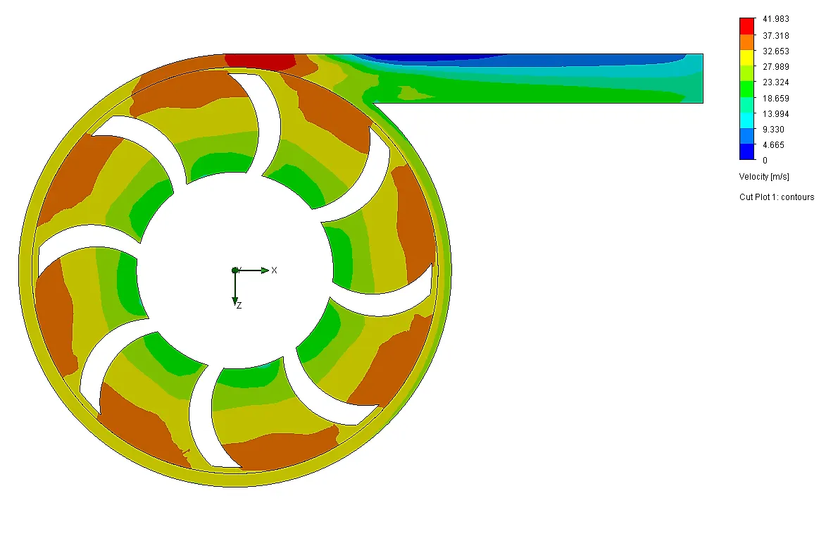
Cut plot:
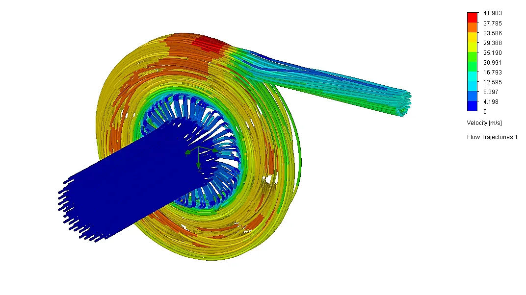
Flow Trajectories:
4.3 Design Point 3 (Velocity 20m/s):-
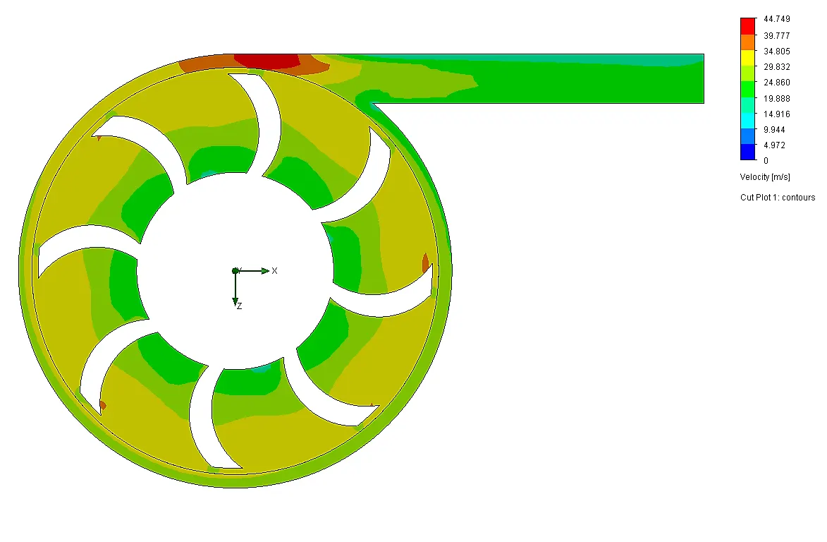
Cut plot:
Flow Trajectories:
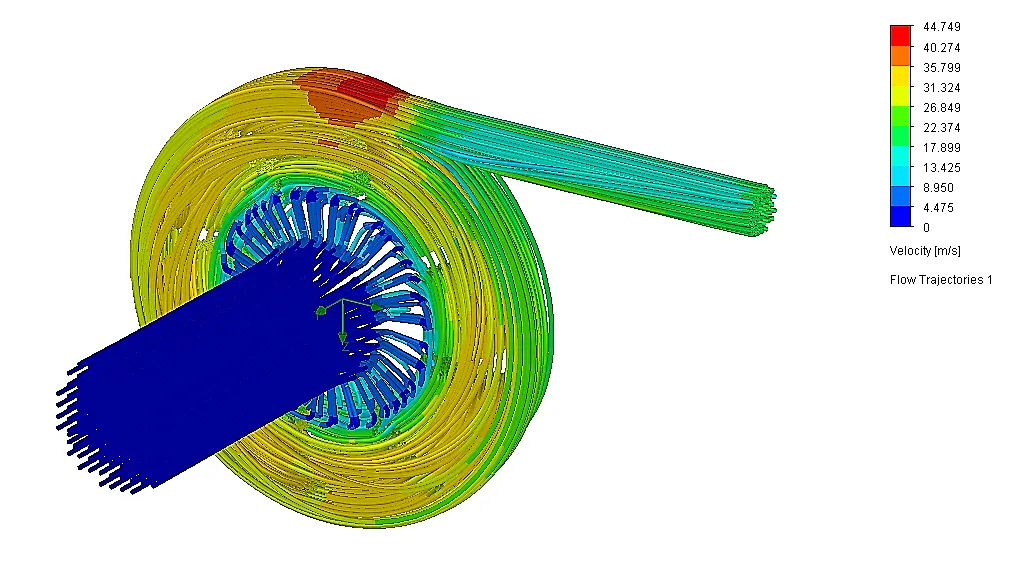
4.4 Design Point 4 (Velocity 25m/s):-
Cut plot:
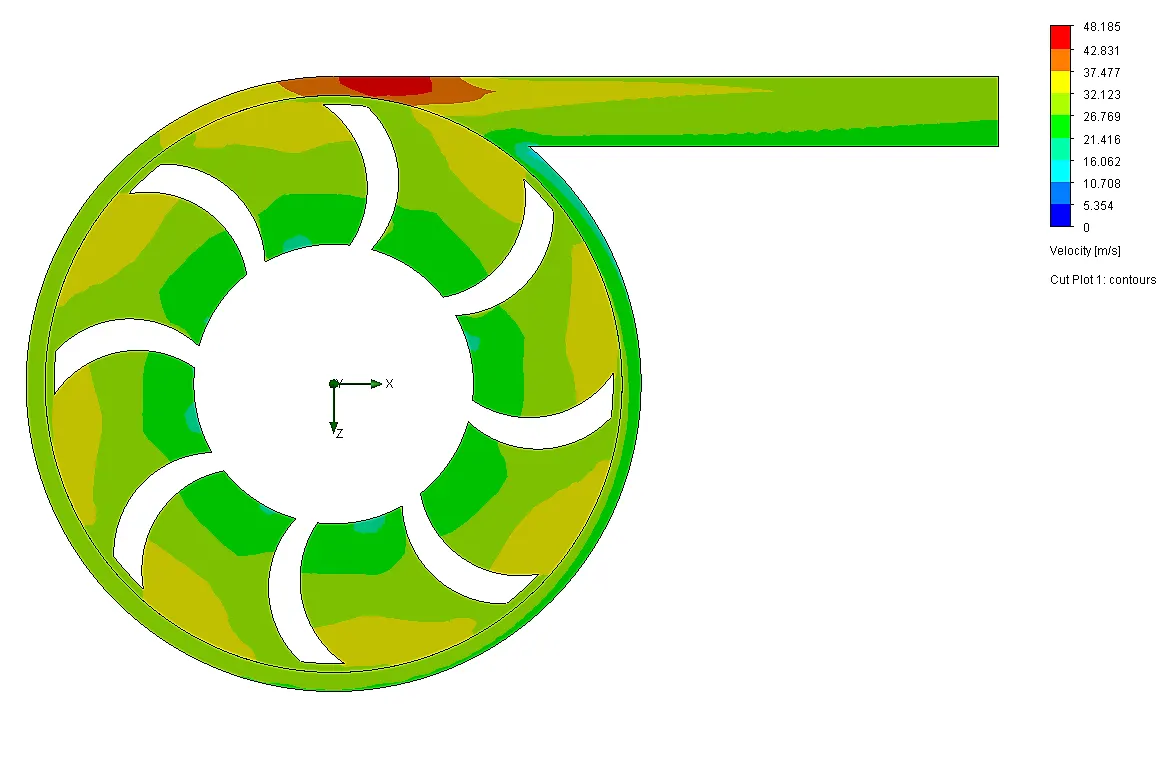
Flow Trajectories:
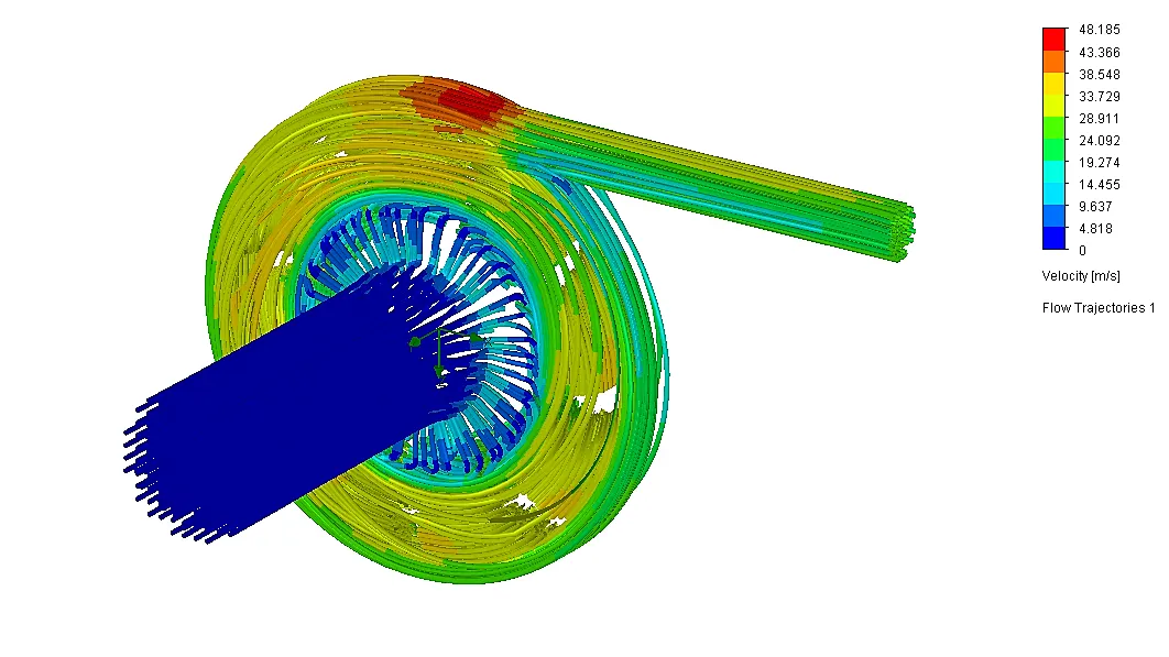
4.5 Design Point 5 (Velocity 30m/s):-
Cut plot:
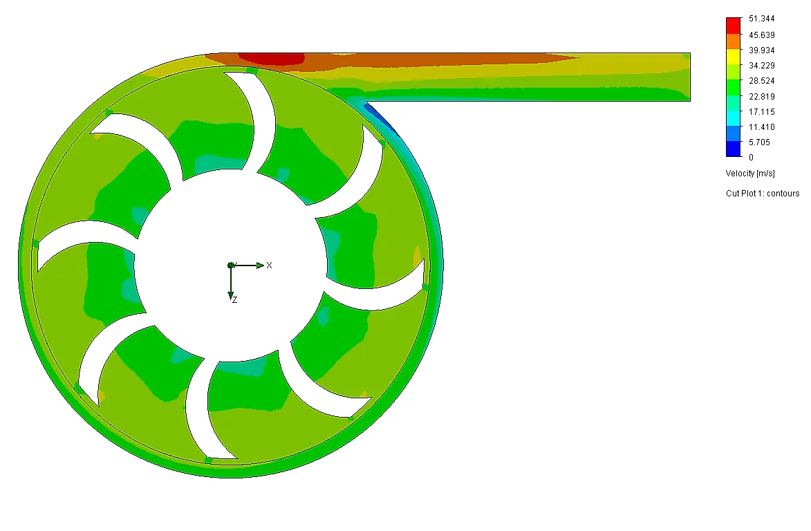
Flow Trajectories:
5. Observation and Conclusion:-
Calculated Parameters:

5.1 Pressure At inlet and Outlet:-
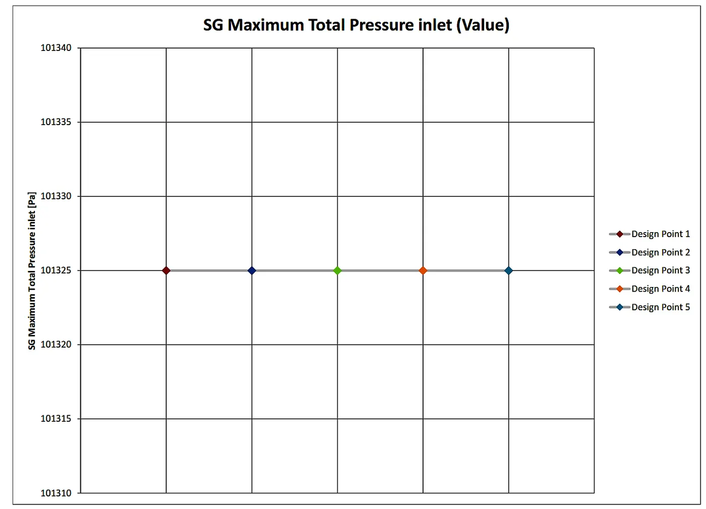
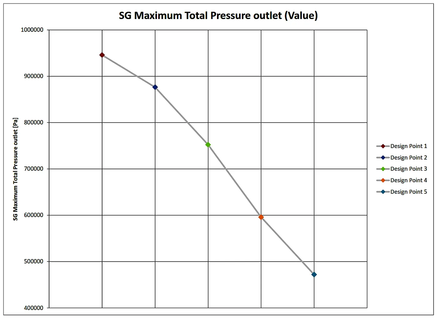
At the inlet, the pressure is constant in all the designed points (i.e Velocity ranges) while the outlet pressure decreases with the increase in velocity. This is caused due to the flow reaches to the
5.2 Performance Analysis:-
For the performance analysis of a Centrifugal Pump, we need to get the plot of pressure ratio (vs) Mass flow rate. Hence, to get this first we need the pressure ratio which is as follows.
Pressure ratio:
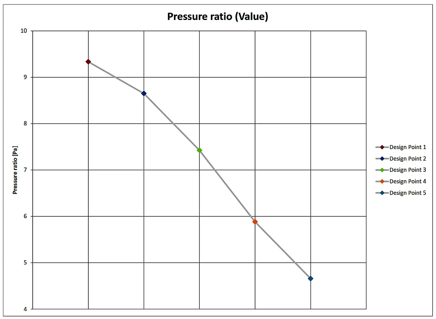
The pressure ratio in the centrifugal pump is the ratio of pressure at the outlet to pressure at the inlet. To get the pressure ratio we used equation goal. the basic formula is as follows.
'Pressure ratio = Outlet total pressure/ Inlet total pressure'
Pressure ratio (vs) Mass flow rate:
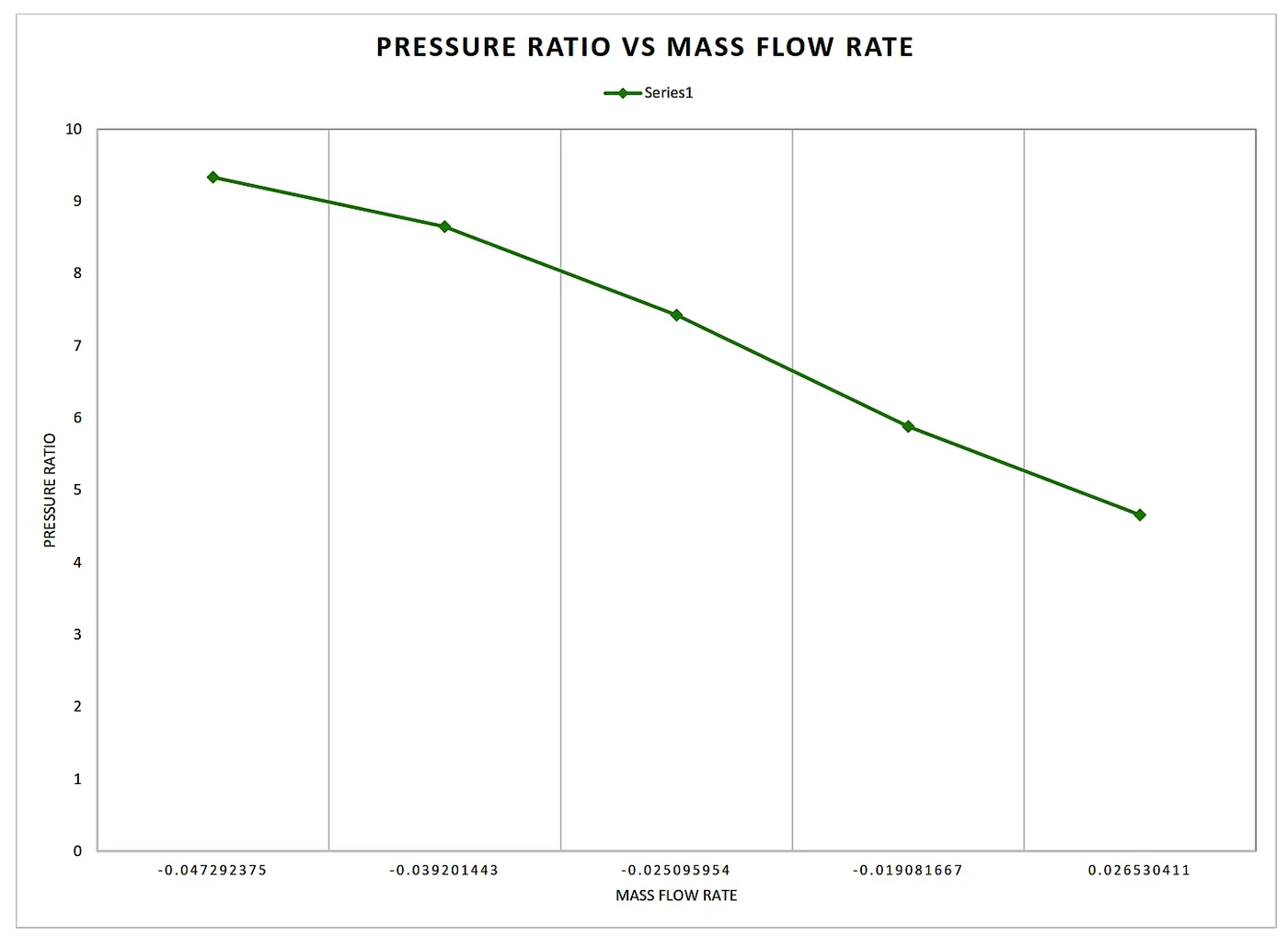
From the above plots of pressure ratio with respect to each iteration and mass flow rate indicates that the pressure ratio decreases with an increase in the mass flow rate and velocity.
5.3 Mass Flow rate:-
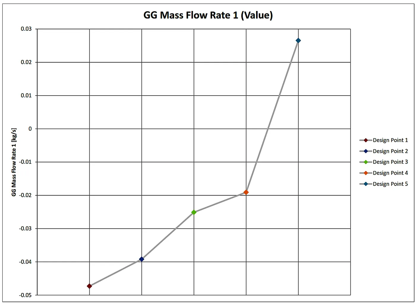
Mass Flow rate Global Goal:
Mass Flow rate Surface Goal:
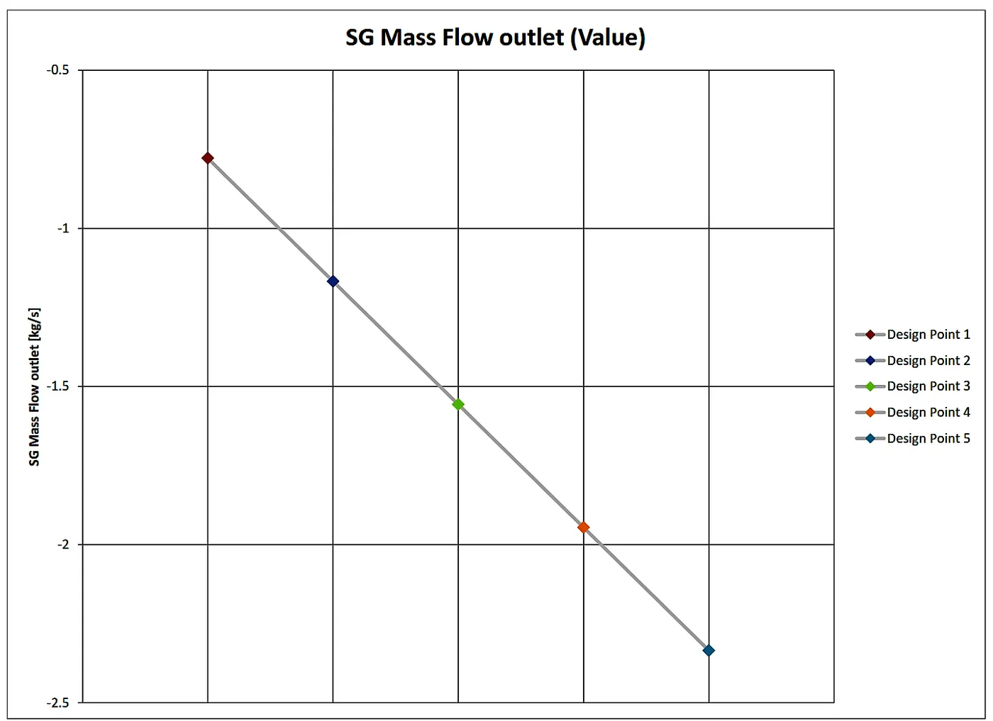
From the above two plots of the mass flow rate, we can conclude that as the velocity increases the mass flow rate is also increases (i.e Velocity is directly proportional to the outlet mass flow rate). where the negative sign in the surface goal plot of the mass flow rate indicates that the mass leaving from the system.