Centrifugal pump design and analysis
Introduction:
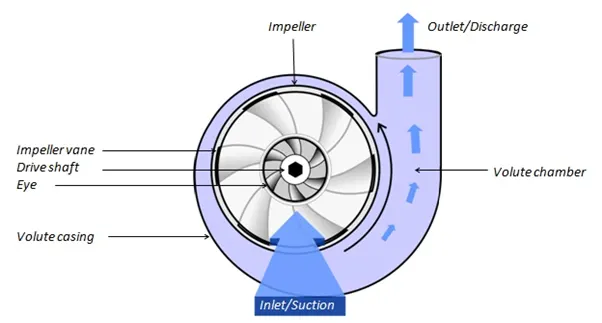
A Centrifugal Pump is a hydraulic machine used to raise the liquids from a lower to a higher level by creating a required pressure by means of centrifugal action. These are the machines that increase the pressure energy of a fluid. These may either lift the fluid or just boost the pressure in a pipeline.
Working of Centrifugal Pump:
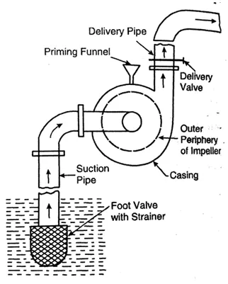
Before starting the pump, priming is done. In priming, water is filled in the suction pipe, casing, and into a portion of the delivery pipe up to the delivery valve. This is done for the removal of air. If the impeller is run in air, no liquid will be lifted by the pump. It should be noted that during priming, the delivery valve is kept closed. After priming, the delivery valve is still kept closed and the prime mover is started to rotate the impeller. The rotation of the impeller in the casing full of liquid produces a centrifugal head in the liquid and thus pressure in the whole of liquid is increased.
After a short period, when the pump attains a constant speed delivery valve is gradually opened and thus liquid is allowed to flow in a radially outward direction through the impeller vanes and attains higher velocity. The water at high pressure rises through the delivery pipe into the desired height. At the same time, centrifugal action creates a partial vacuum at the center of the impeller, known as 'eye'. The partial vacuum causes the water to rush through the suction pipe towards the impeller eye, to take the place of water which has left the impeller vanes from the sump.
Applications:
Common uses include water, sewage, agriculture, petroleum, and petrochemical pumping. Centrifugal pumps are often chosen for their high flow rate capabilities, abrasive solution compatibility, mixing potential, as well as their relatively simple engineering. A centrifugal fan is commonly used to implement a vacuum cleaner. The reverse function of the centrifugal pump is a water turbine converting the potential energy of water pressure into mechanical rotational energy.
Objective:
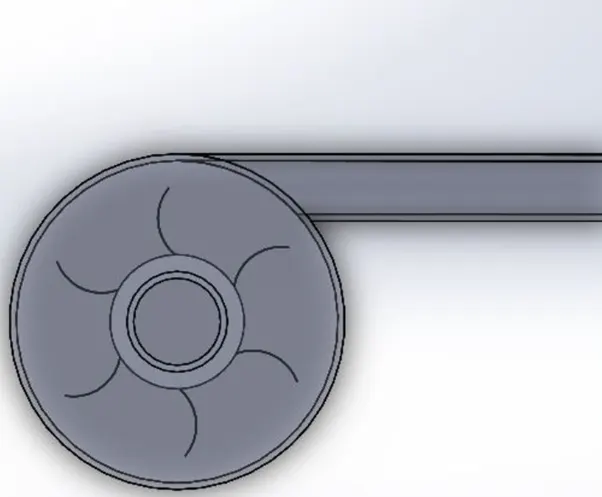
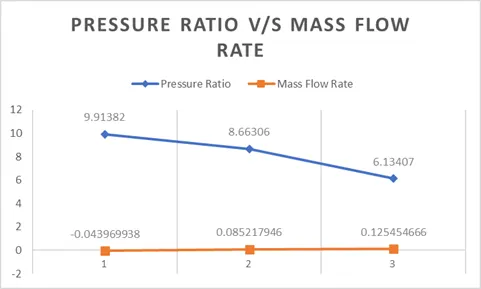
The project is a study that aims to design and develop a model of a centrifugal pump and analyze the various parameters such as the velocity, pressure at the outlet and Inlet, mass flow rate, etc.. Also, to simulate the flow of water through the centrifugal pump evaluating pressure and the velocity of the flow. The aim of the project is to calculate the pressure ratio based on the pressure at the outlet and inlet and result in developing a performance diagram (plot of mass flow rate v/s pressure-ratio)
Pressure Ratio = Outlet total pressure/ Inlet total pressure
Parameters for Base Line Simulations:
Analysis type: - Internal
Fluid Used: - Water
Type of Flow: - Laminar and Turbulent
Rotation Type: - Local Region Averaging
Procedure:
1. First create a 3D model of a centrifugal pump using some dimensions
2. After that go to the flow simulation give the input parameters select the liquid as water.
3. Then add the boundary conditions- for the first rotation, select the region of rotation at 1000 rad/sec, enter input for environmental pressure and outlet as velocity at 10 m/sec
4. The surface goal is set inlet and outlet for the total pressure and add the surface mass flow rate.
5. Set the mesh grid automatically as level 3 and advanced channel refinement.
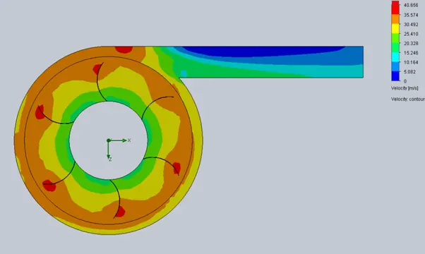
6. Run the simulation and the cut plot is created for the velocity and velocity trajectory.
Output:
Outlet Velocity with different velocity conditions and cut plots.
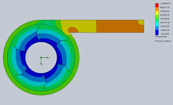
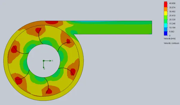
Case 1: Outlet velocity at 10 m/s
Velocity Cut Plot
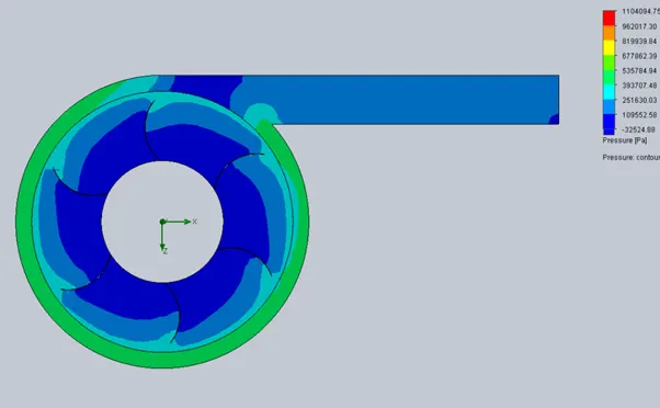
Pressure Cut plot
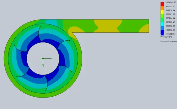
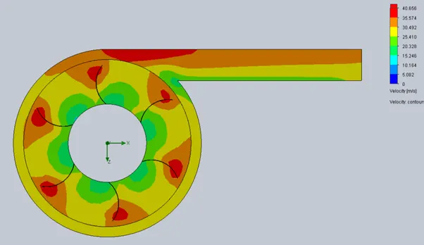
Case 2: Outlet velocity at 20 m/s
Velocity Cut Plot
Pressure Cut plot
Case 3: Outlet velocity at 30 m/s
Velocity Cut Plot
Pressure Cut plot
Analysis:
| Velocity | SG Av Total Pressure Outlet (Pa) | SG Av Total Pressure Outlet (Pa) | Pressure Ratio | Mass Flow Rate |
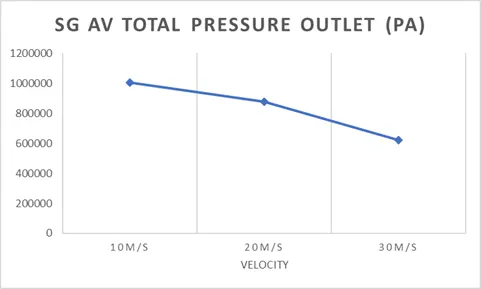
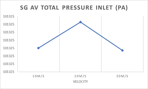
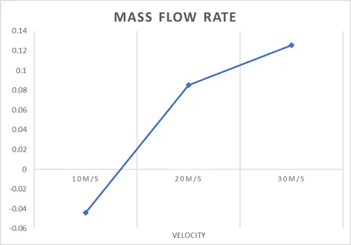
| 10 m/s | 1004518.103 | 101324.999 | 9.91382 | -0.043969938 |
| 20 m /s | 877785.5231 | 101325.0023 | 8.66306 | 0.085217946 |
| 30 m/s | 621535.011 | 101324.9987 | 6.13407 | 0.125454666 |
Conclusion:
When Outlet velocity gets increased, the pressure value gets decreased. Therefore, outlet velocity is inversely proportional to pressure as outlet velocity increased, the total average outlet pressure value gets decreased.
With an increase in outlet velocity, the average mass flow rate showed a linear variation in the negative direction and hence it increases.
With an increase, in the outlet velocity, the mass flow also increases.