Centrifugal pump design and analysis by using an SOLIDWORKS
AIM :
To modelling the centrifugal pump and run a computational fluid dynamics simulation for different velocity of outlet and extracting useful data from numerical mathematical model such as mass flow rate, total pressure of inlet and outlet.
FLOW OF CONTENT/METHODOLOGY :
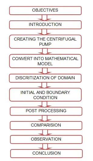
OBJECTIVE :
1) Create a centrifugal pump model with inlet passage and outlet passage.
2) Assign the boundary condition for total inlet pressure and total outlet pressure.
3) Create a moving reference frame around the impeller and assigning a fluid should rotates at constant speed.
4) Calculating the parametric study of different velocity by using those values to finding the pressure ratio.
INTRODUCTION :
i) CENTRIFUGAL PUMPS :
The hydraulic machines which converts mechanical energy into hydraulic energy are called pumps. The hydralic energy is in the form of pressure energy. If the mechanical energy is converted into pressure energy by means of centrifugal force acting on the fluid, the hydraulic machine is called centrifugal pumps.
The centrifugal pump acts as a reverse of an inward radial flow reaction turbine. This means that the flow in centrifugal pumps is in the radial outward direction. The centrifugal pumps works on the principle of forced vortex flow which means that when a certain mass of liquid takes place. The rise in pressure head at any point of the rotating liquid is proportional to the square of tangential velocity of the liquid at that point. Thus at the outlet of the impeller, where radius is more, the rise in pressure head will be more and the liquid will be displayed at the outlet with a high pressure head. Due to this high pressure head, the liquid can be lifted can be lifted to a high level.
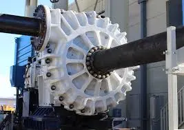
Main parts of a centrifugal pumps :
Impeller :
The rotating part of a centrifugal pump is called "impeller". It consists of a series of backward curved vanes. The impeller is mounted on a shaft which is connected to the shaft of an electric motor.
Casing :
The casing of a centrifugal pump is similar to the casing of a reaction turbine. It is an air-tight passage surrounding the impeller and is designed in such a way that the kinetic energy of the water discharged at the outlet of the impeller is converted into pressure energybefore the water leaves the casing and enters the delivery pipe. The following three types of the casings are commonly adopted :
a) Volute casing
b) Vortex casing
c) Casing with guide blades
Suction pipe with a foot valve and a strainer :
A pipe whose one end is connected to the inlet of the pump and other end dips into water in a sump is known as suction pipe. A foot valve which is a non return valve or one way type of valve is fitted at the fitted at the lower end of the suction pipe. The foot valve opens only in the upward direction. A strainer is also fitted at the lower end of the suction pipe.
Delivery pipe :
A pipe whose one end is connected to the outlet of the pump and other end delivers the water at a required height is known as delivery pipe.
ii) MOVING REFERENCE CONCEPT :
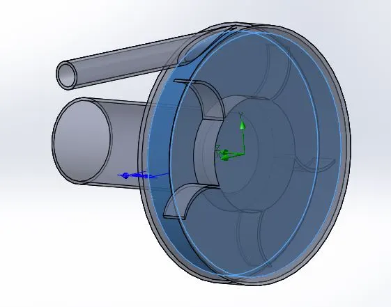
A selected region is Moving reference frame, the MRF model is the simplest of the two approaches for multiple zones. It is a steady-state approximation in which individual cell zones move at different rotational or translational speeds. The flow in each moving cell zone is solved using the moving reference frame equations. If the zone is stationary `omega = 0`, the stationary equations are used i.e., moving reference frame equations are solved in rotational zone and stationary equations are solved in stationary zone and the information is exchanged at the interface. The properties of the flow at the interface between the stationary and rotating zones is directly translated in MRF. In MRF approach there is no relative motion between moving zone with respect to the adjacent zone, the grid is fixed for computation. This is analogous to freezing the motion of the moving part in a specific position and observing the instantaneous flow field with the rotor in that position and hence, the MRF is often referred to as the "frozen rotor approach."
CREATING THE CENTRIFUGAL PUMP :
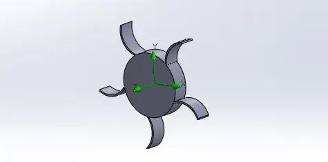
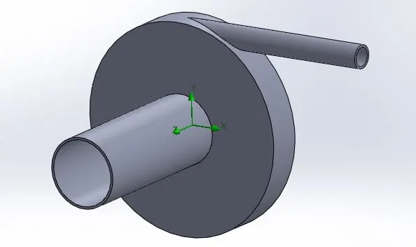
1) First, creating the impeller by using options are circle, arc, trimming and finally extrude with appropriate dimensions. After that, creating the volute casing by using circle and extrude option make sure uncheck the merge option.
2) Afterthat, creating the inlet chamber on the volute case and also create the outlet chamber tangent to the impeller, make sure uncheck the merge option before extruding.
3) By using combine option for which combining into the single component without merging into each other.
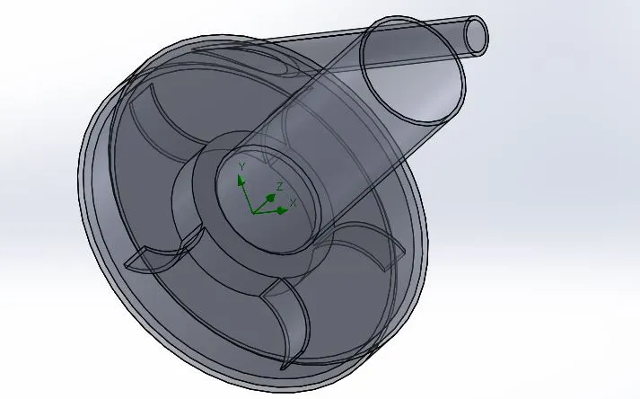
Transparent view of centrifugal pump :
To reduce the transparentcy of inlet chamber, outlet chamber and volute case for which visualize the interior part.
CONVERT TO MATHEMATICAL MODEL:
Wizard Analysis Type :
Unit system - SI
Flow type - Internal
Physical feature :
Rotation - Local regions (Averging)
Working fluid - Water
Pressure - 101325 pascals
Temperature - 293 K
DISCRITIZATION OF DOMAIN :
The process of discritize the mathematical domain is divided into finite cells or elements is called meshing. The whole constrainted domain is splited into small piece, the governing eqaution is solved in each and every element or cell.
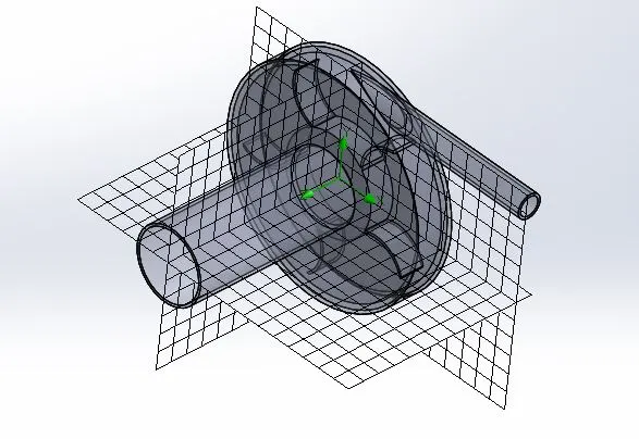
Mesh specification :
Fluid cells - 87905
Fluid cells contacting solids - 44218
Select the Advanced channel refinement for which concern complex regions.
INITIAL AND BOUNDARY CONDITIONS :
We had created the moving reference frame, provide the angular velocity of 1000 rad/sec for which it rotates about centeral axis.
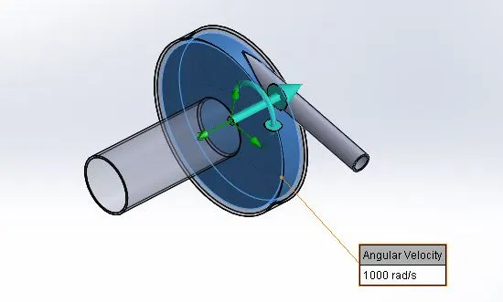
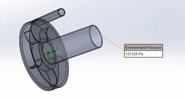
Provide the inlet boundary condition of environment pressure is 101325 pascals.
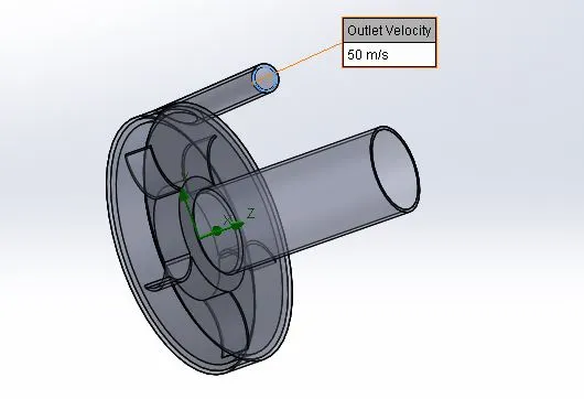
Provide the outlet velocity boundary condition is range between of 10 m/s to 60 m/s with 6 intervals.
POST PROCESSING :
Velocity dependency test :
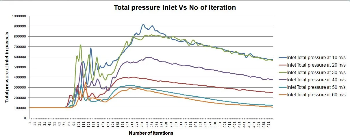
Create a parametric study for which calculating the mass flow rate at outlet depends on outlet velocity and also calculate the total pressure inlet and outlet pressure outlet.
Case 1
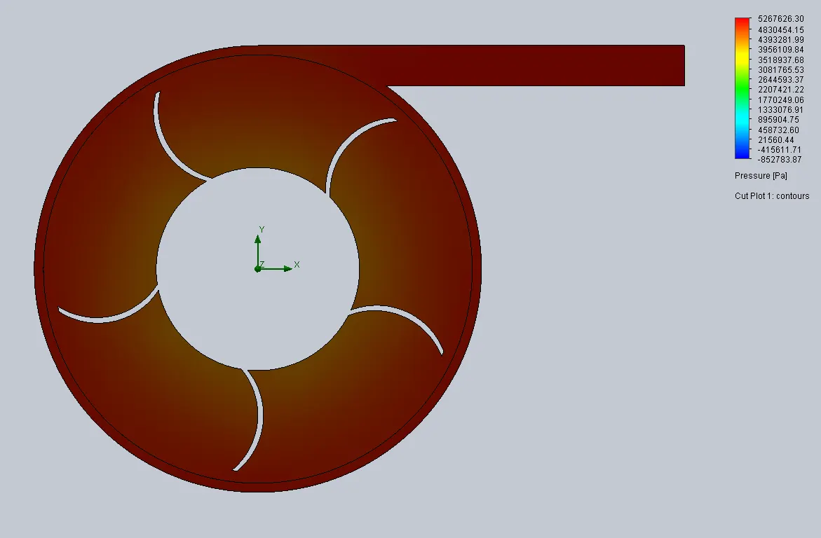
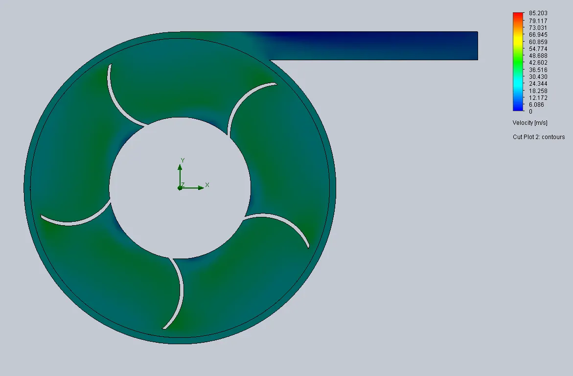
Outlet velocity is 10 m/s
Pressure contour :
Velocity contour :
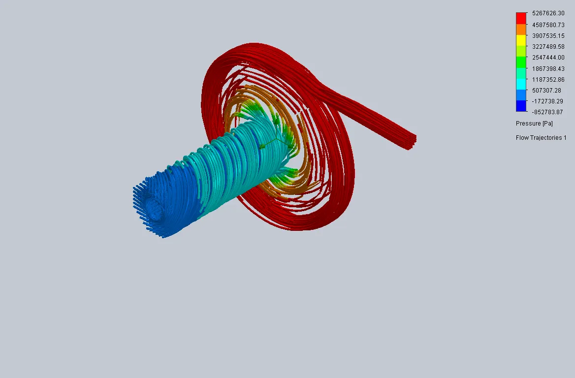
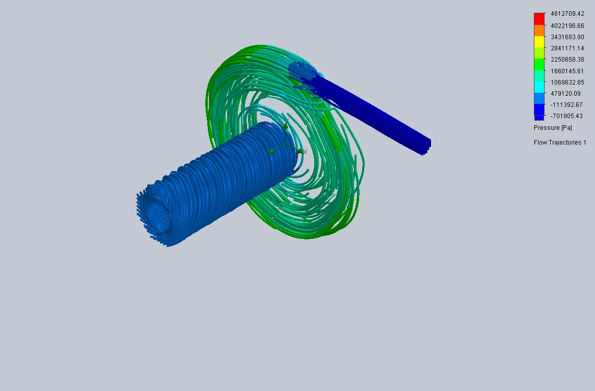
Flow trajectories for pressure :
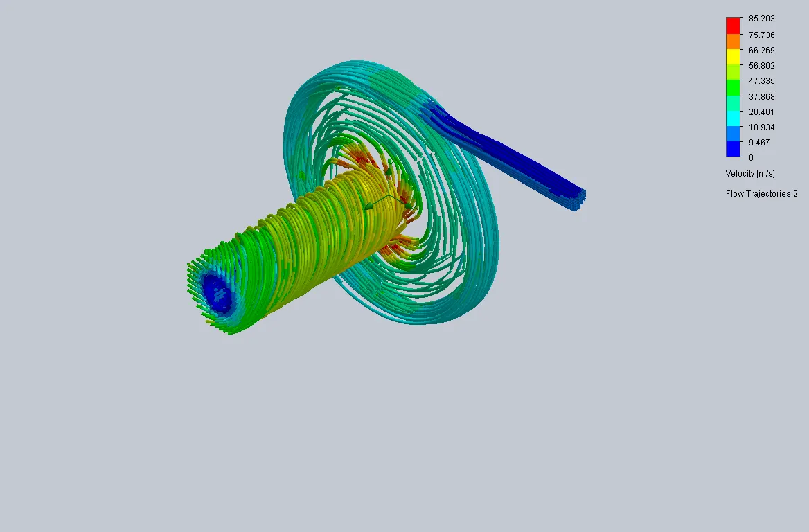
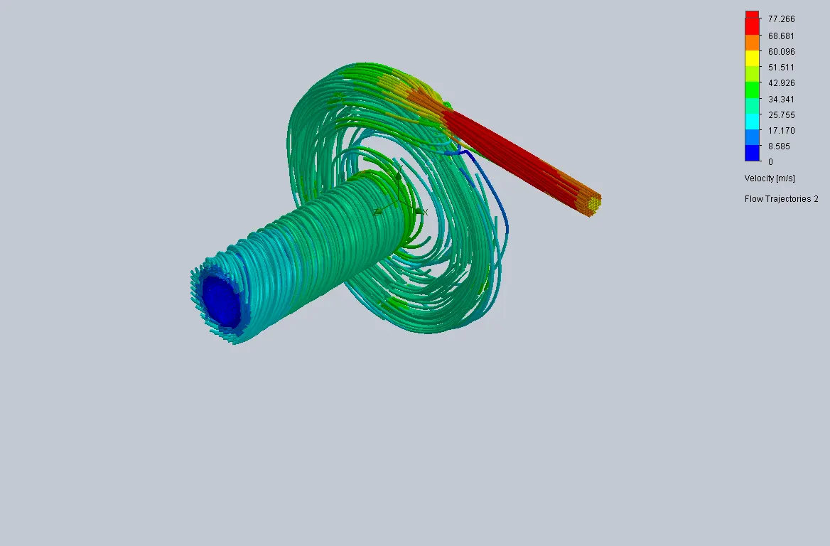
Flow trajectories for velocity :
Case 2
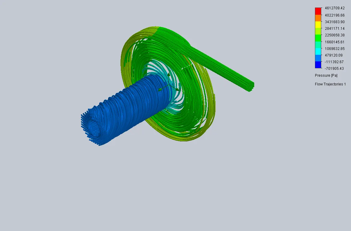
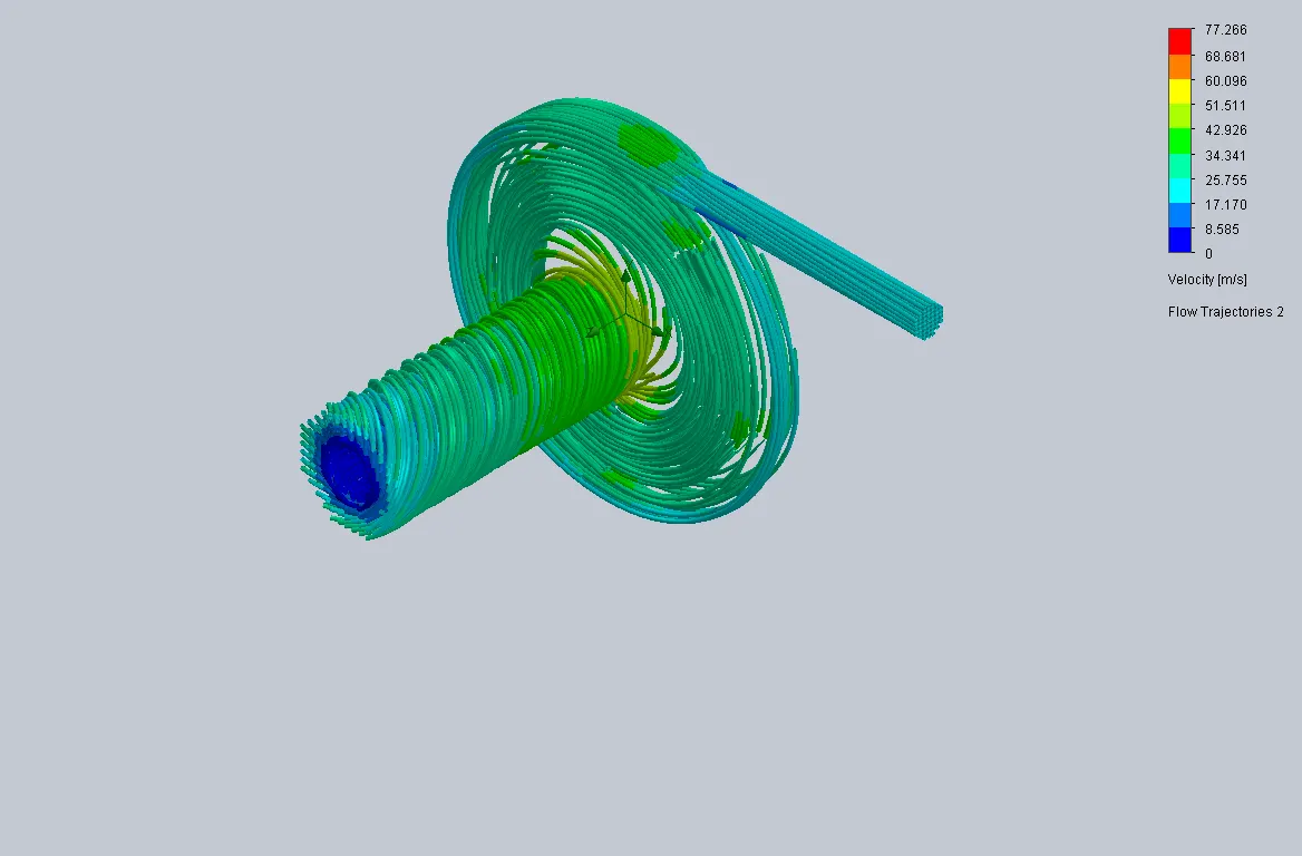
Outlet velocity is 20 m/s
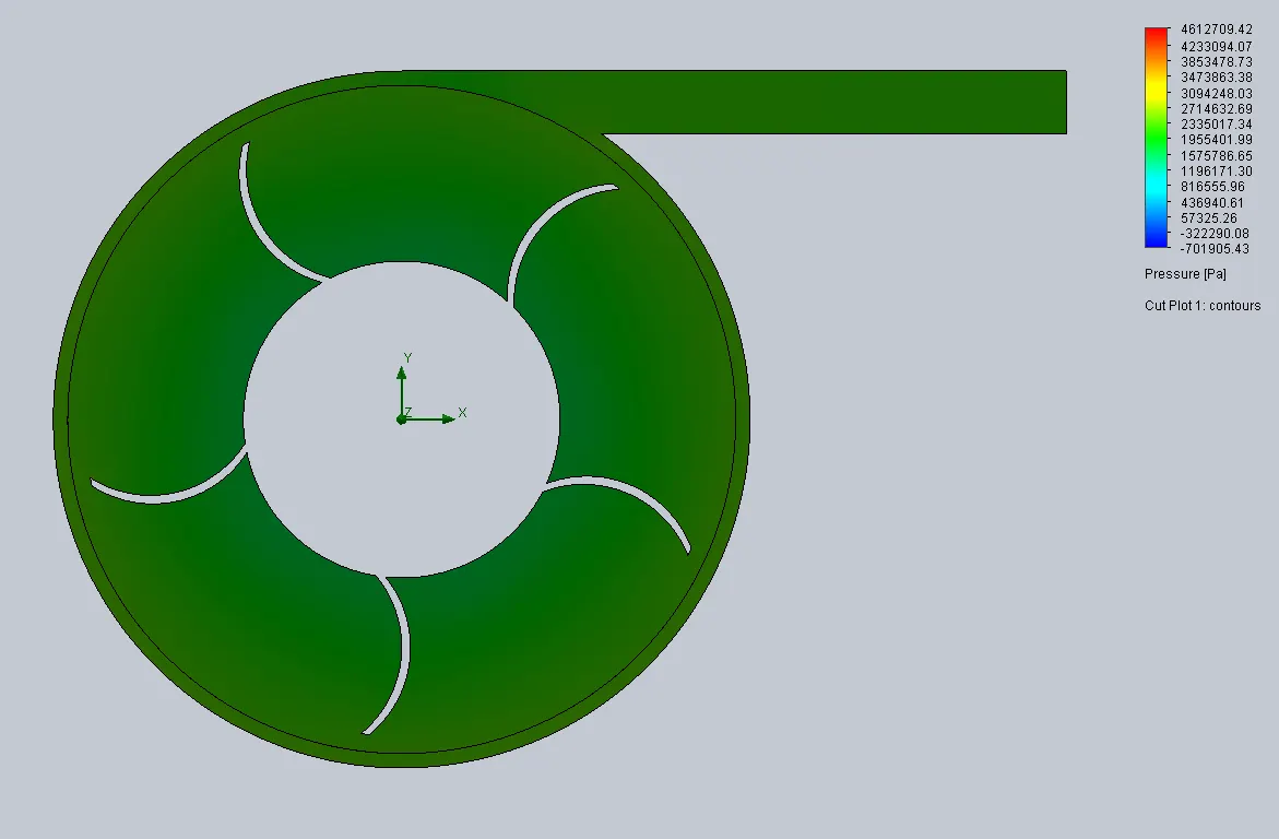
Pressure contour :
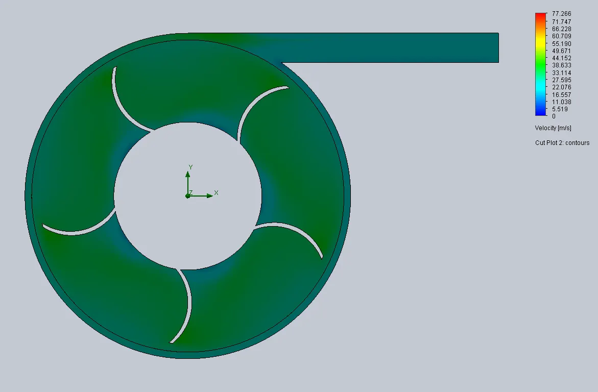
Velocity contour :
Flow trajectories for pressure :
Flow trajectories for velocity :
Case 3
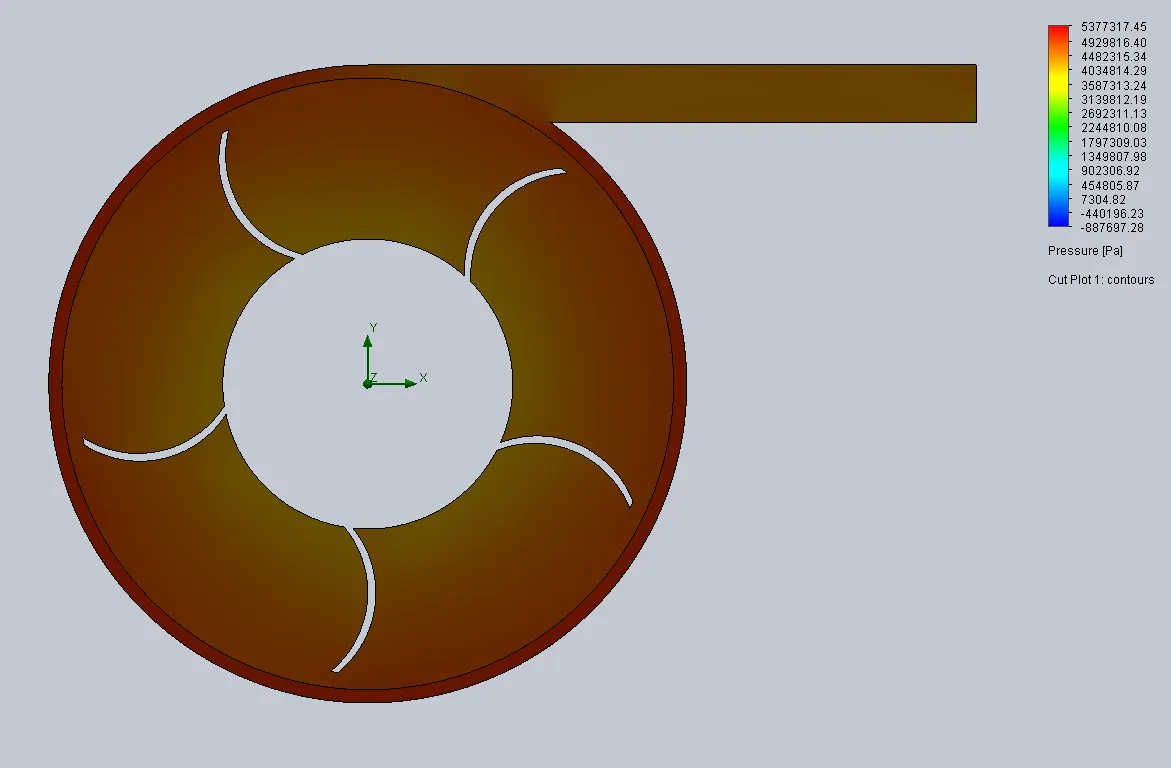
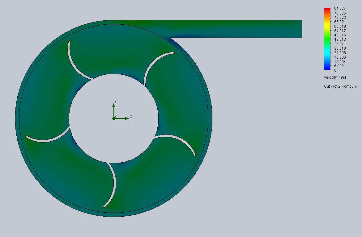
Outlet velocity is 30 m/s
Pressure contour :
Velocity contour :
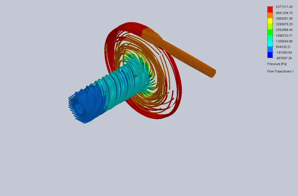
Flow trajectories for pressure :
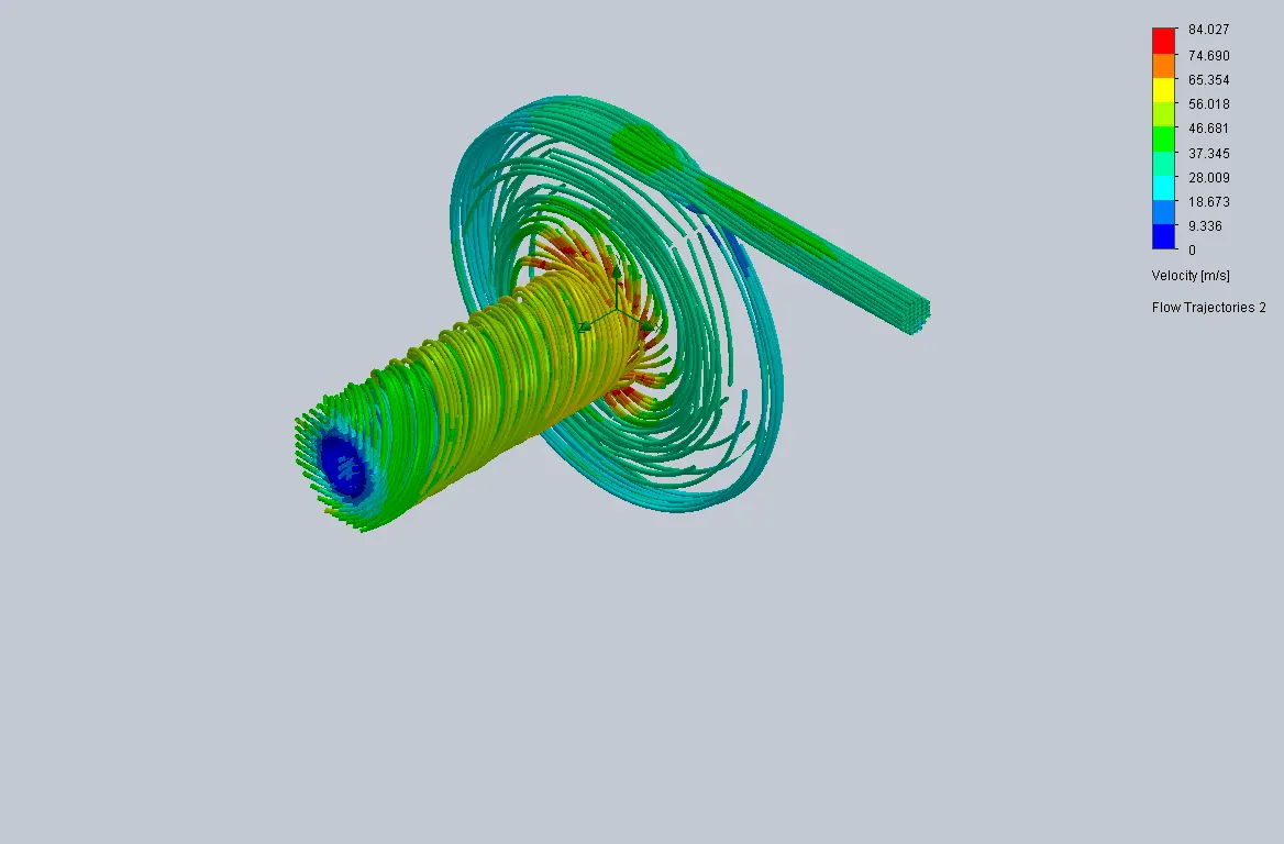
Flow trajectories for velocity :
Case 4
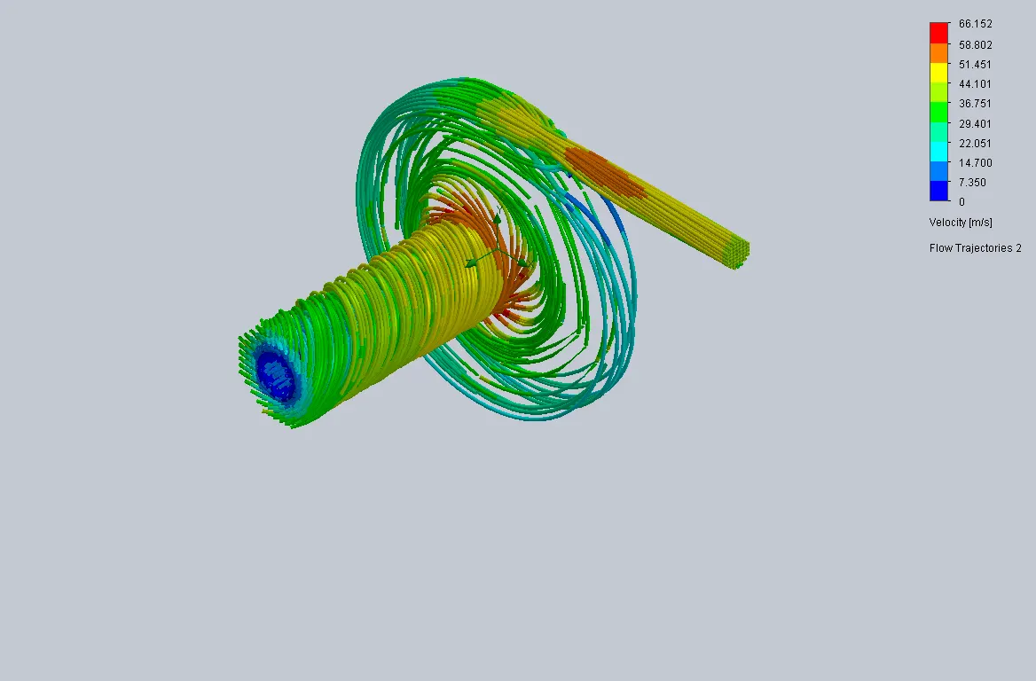
Outlet velocity is 40 m/s
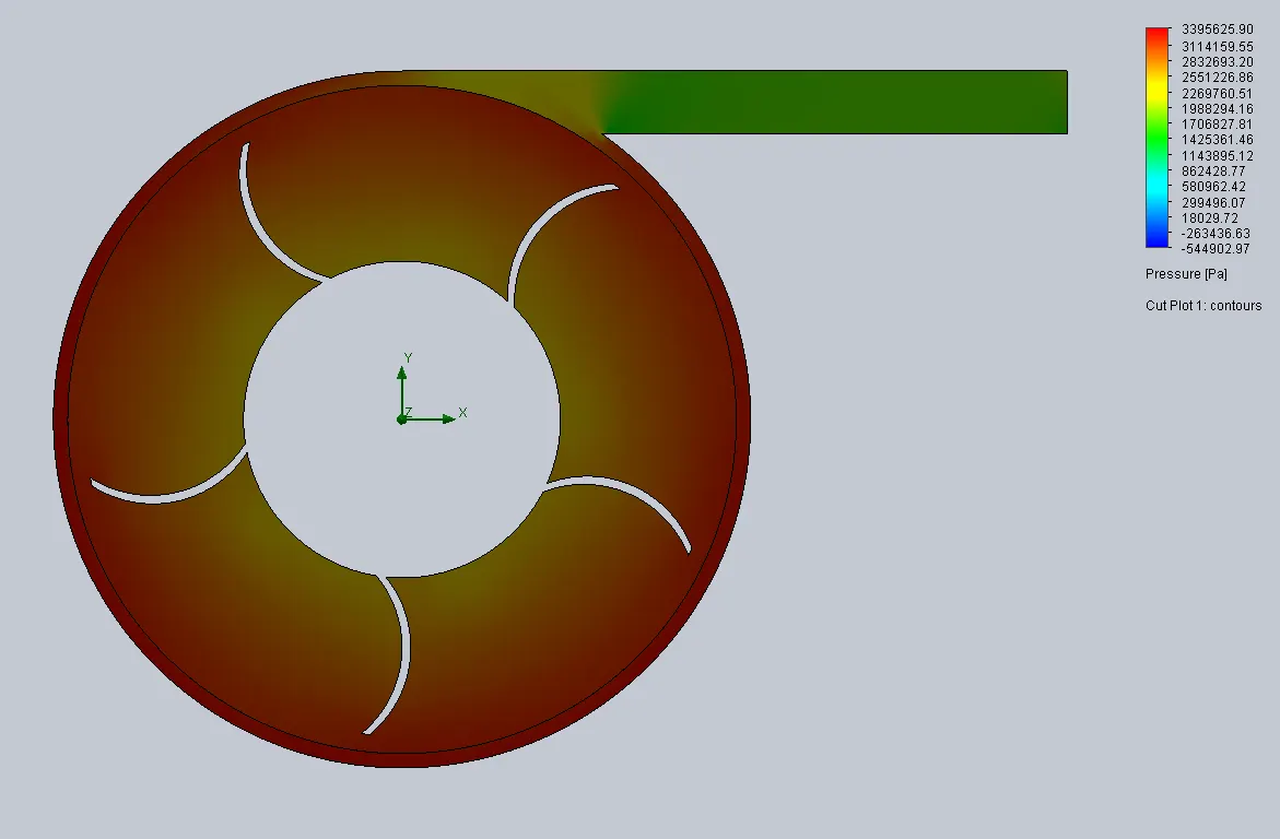
Pressure contour :
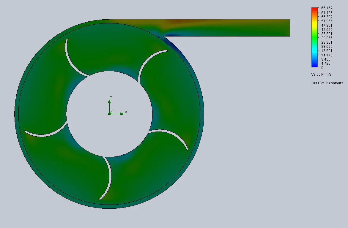
Velocity contour :
Flow trajectories for pressure :
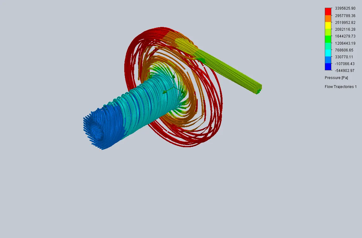
Flow trajectories for velocity :
Case 5
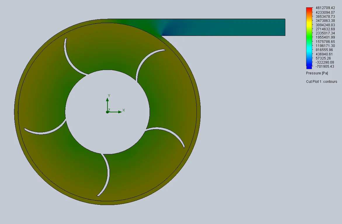
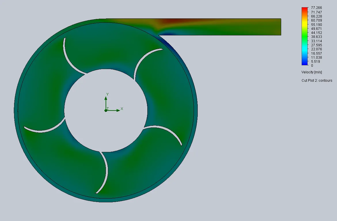
Outlet velocity is 50 m/s
Pressure contour :
Velocity contour :
Flow trajectories for pressure :
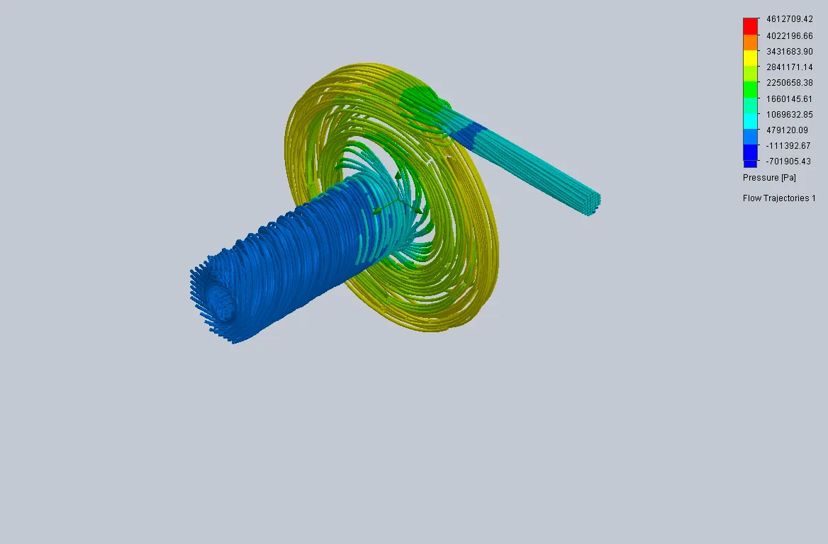
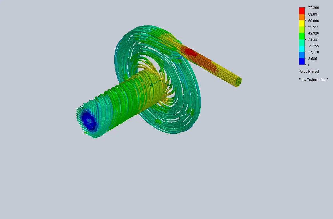
Flow trajectories for velocity :
Case 6
Outlet velocity is 60 m/s
Pressure contour :
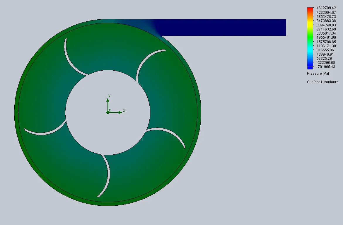
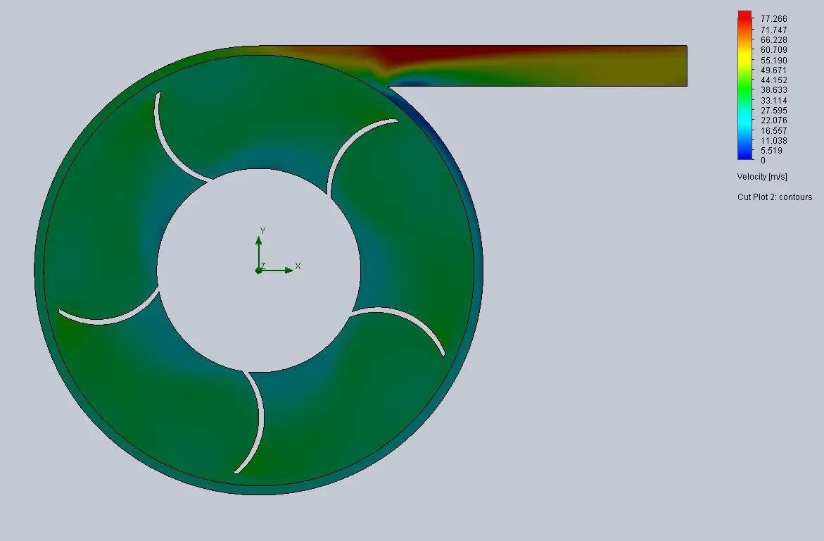
Velocity contour :
Flow trajectories for pressure :
Flow trajectories for velocity :
COMPARISION :
Goals for all cases :

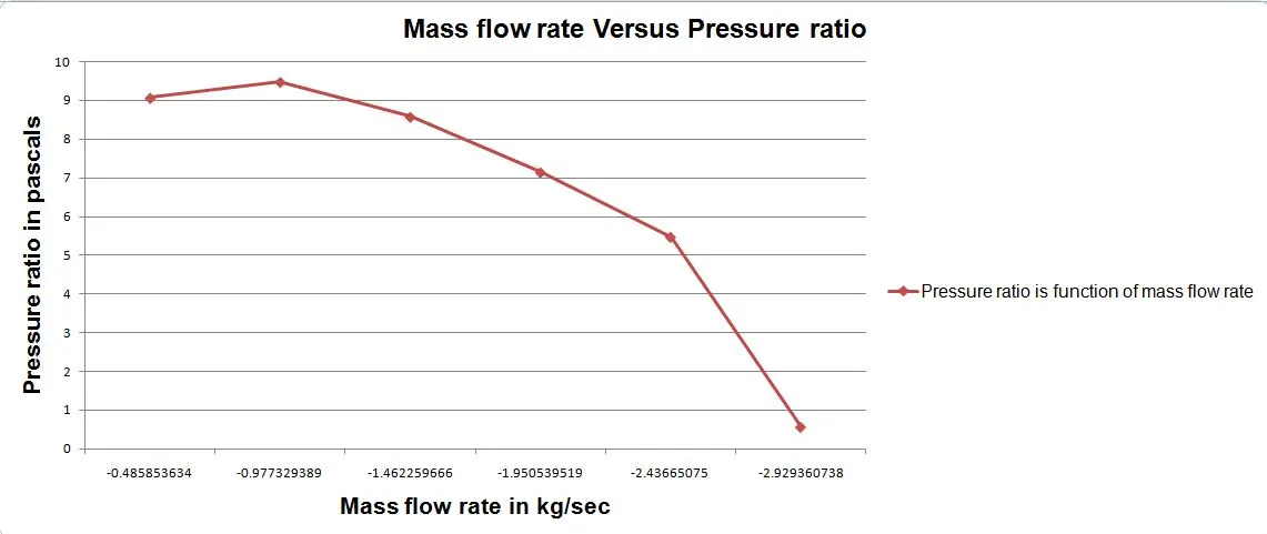
Mass flow rate Vs Pressure ratio :
A pump performance curve is indicates how a pump will perform in regrads inlet total pressure, outlet total pressure and mass flow. A curve is defined specific operating speed in revolution per minute and specific inlet and outlet diameter.
Also curve shows the optimum design for maximum efficiency.
Pressure ratio = Outlet total pressure/Inlet total pressure
Inlet total pressure for all cases :
Outlet total pressure for all cases :
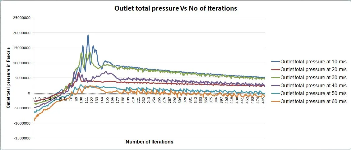
OBSERVATION :
1) All the cases obey bernoullie's equation, it states that an increase in the speed of a fluid occurs simultaneously with a decrease in static pressure or a decrease in the fluid's potential energy.
2) When the mass flow rate outlet or velocity of fluid is increased, it inversely proportional to Pressure ratio.
3) A pressure is comes under the environment pressure, a suction is happened.
4) The moving reference frame rotates and sucked from the water on that is pressure is low compared to outlet.
CONCLUSION :
Finally, to ran the centrifugal pump flow simulation with the different mass flow rate and correspondingly plotted the pressure ratio on single graph.
REFERANCE :