Centrifugal pump design and analysis
Aim :- Centrifugal pump design and analysis in solid Works.
Introduction :- Centrifugal pumps are used to transport fluids by the conversion of rotational kinetic energy to the hydrodynamic energy of the fluid flow. The rotational energy typically comes from an engine or electric motor. They are a sub-class of dynamic axisymmetric work-absorbing turbomachinery. The fluid enters the pump impeller along or near to the rotating axis and is accelerated by the impeller, flowing radially outward into a diffuser or volute chamber (casing), from which it exits. Like most pumps, a centrifugal pump converts rotational energy, often from a motor, to energy in a moving fluid. A portion of the energy goes into kinetic energy of the fluid. Fluid enters axially through eye of the casing, is caught up in the impeller blades, and is whirled tangentially and radially outward until it leaves through all circumferential parts of the impeller into the diffuser part of the casing. The fluid gains both velocity and pressure while passing through the impeller. The doughnut-shaped diffuser, or scroll, section of the casing decelerates the flow and further increases the pressure. Centrifugal Pumps are the most popular and commonly used type of pump for the transfer of fluids. In simple words, it is a pump that uses a rotating impeller to move water or other fluids by using centrifugal force. These are the undisputed pump choice especially for delivering liquid from one location to another in numerous industries including agriculture, municipal (water and wastewater plants), industrial, power generation plants, petroleum, mining, chemical, pharmaceutical, and many others. Centrifugal Pumps are useful since they can generally handle large quantities of fluids, provide very high flow rates (which may vary with the changes in the Total Dynamic Head (TDH) of the particular piping system) and have the ability to adjust their flow rates over a wide range. Centrifugal pumps are generally designed and suitable for liquids with a relatively low viscosity that pours like water or light oil.
3D Geometry Of centrifugal pump :-
- Blade for centrifugal pump of arbitrary dimension
- Near the blade of centrifugal pump, a cylinderical body is created to rotate the fluid near the blade for more precise result.
- Different views of the blade to check the alignment and dimension of the body.
- Section view of centrifugal pump
############## Setup for initial study :-
- To provide sufficient particles near the pump blade, rotating region is created, which also rotate.
- Inlet Boundry condtion :- Inlet of pump is setup at environmental pressre (101325 Pa)
- Outlet Boundry condtion :- Outlet velocity of the pump is provided (10 m/s)
####### Setup for Parametric Study :-
- Input Variables : velocity at outlet of the pump for the range of ( 10 m/s to 20 m/s for 5 values)
- Output parameter : Mass flow rate, Pressure at the outlet and inlet of the pump to calculate the required data.
- Scenarios: diffrent types of scenario is setup for parametric study to calculate the reaqiured data to achieve goal.
- Goals : - after parametric study, the calculated result can be used to find the performance, characteristics .... of the pump
Result :-
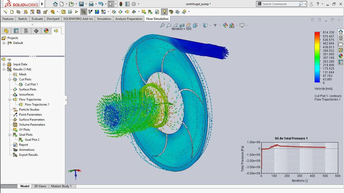
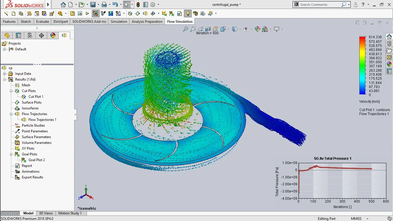
######Output Of the parametric Study :
| Goal (Value) | Design Point 1 | Design Point 2 | Design Point 3 | Design Point 4 | Design Point 5 |
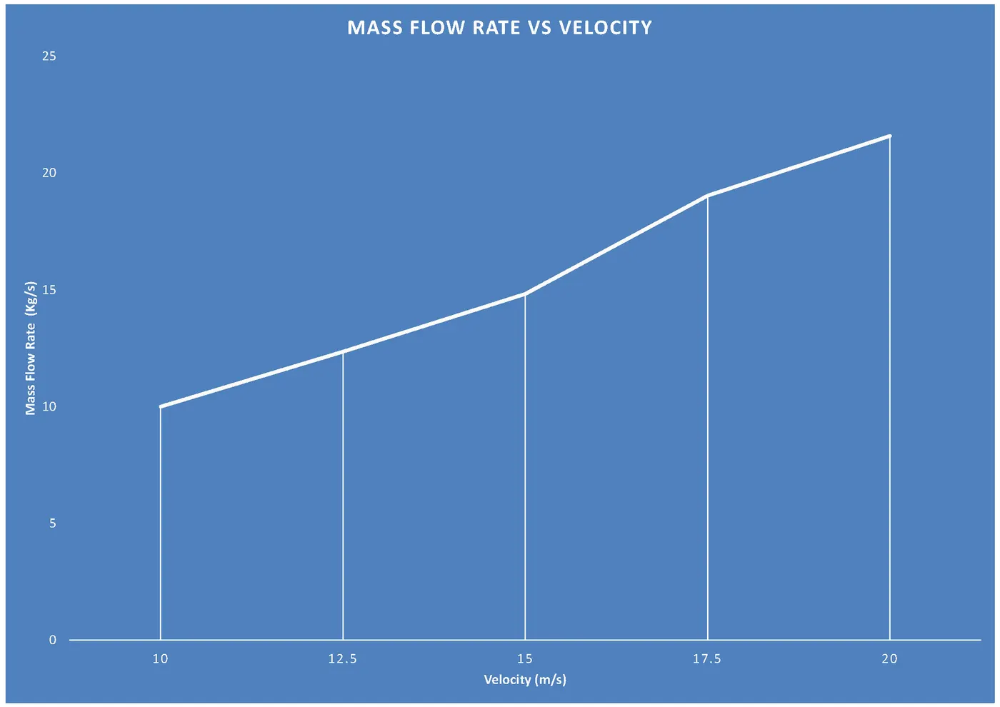
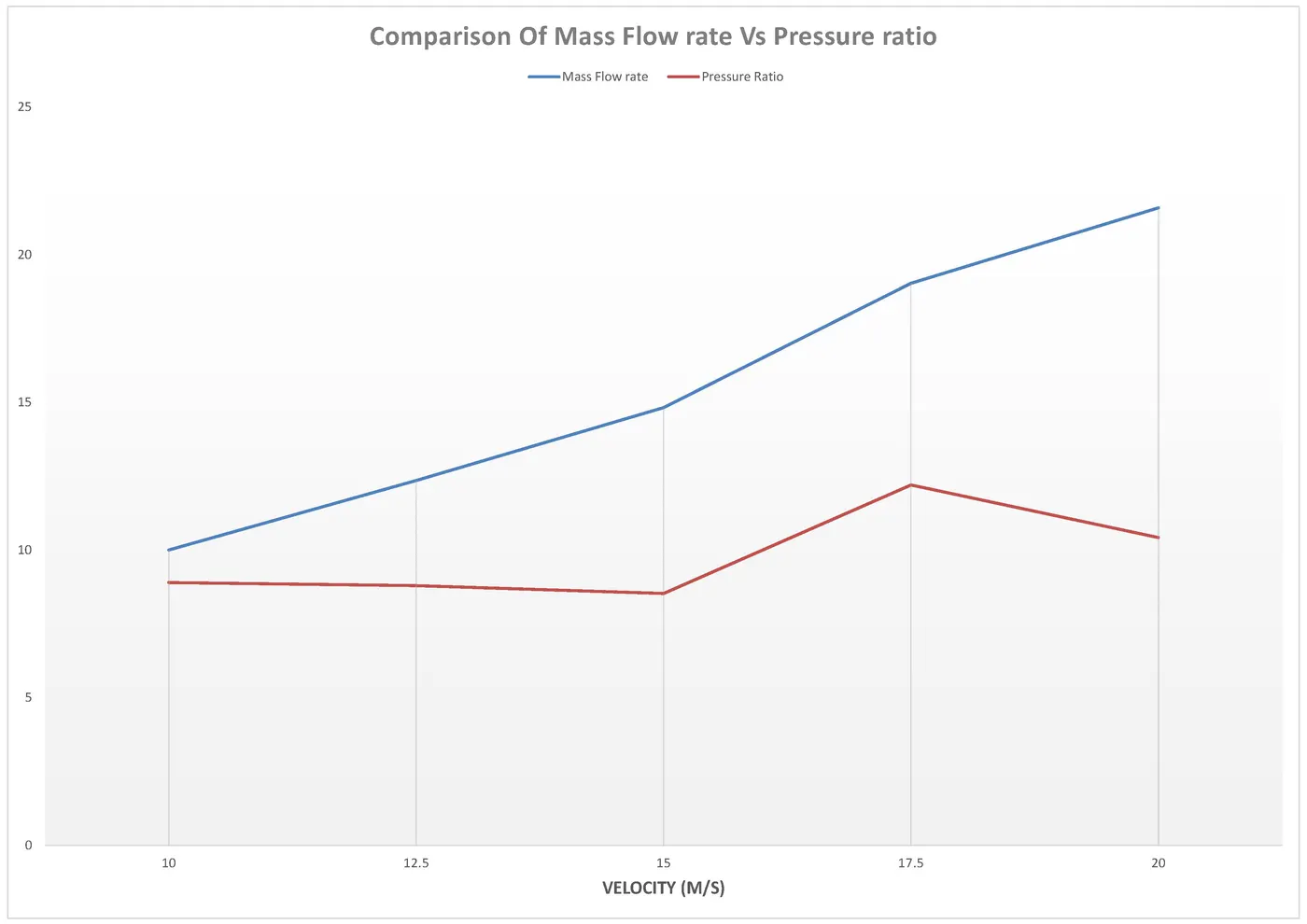
| SG Mass Flow Rate 2 [kg/s] | 9.997080602 | 12.34930366 | 14.81916439 | 19.02798249 | 21.58460823 |
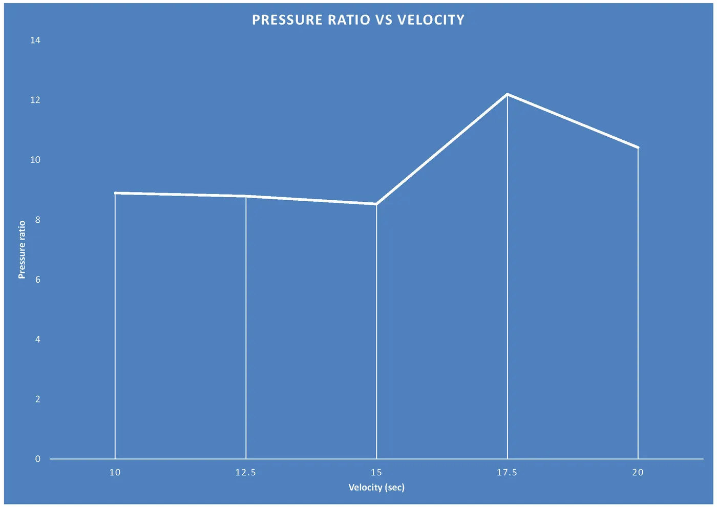
| Pressure Ratio | 8.893121508 | 8.790235699 | 8.526682866 | 12.19954079 | 10.41586405 |
| Velocity normal to face (Outlet Velocity 1) [m/s] | 10 | 12.5 | 15 | 17.5 | 20 |
- Mass Flow Rate Vs Velocity :
- Pressure ratio Vs Velocity :
- Comparison Of Mass flow rate & Pressure ratio Vs Velocity :
Obseravtions & Conclusion :-
- From the First plot we can see that initially, the velocity is less so the mass flow rate is less when the velocity increases the mass flow rate increases.
- From the Second plot, we can see that the pressure ratio is high for low velocity and pressure ratio starts varying as the velocity increases.