Centrifugal Pump design and Analysis
AIM:
To obtain the relationship between Pressure ratio and outlet mass flow rate in a centrifugal pump.
THEORY:
What is a Centrifugal Pump?
A centrifugal pump is a mechanical device designed to move a fluid by means of the transfer of rotational energy from one or more driven rotors, called impellers. Fluid enters the rapidly rotating impeller along its axis and is cast out by centrifugal force along its circumference through the impeller’s vane tips. The action of the impeller increases the fluid’s velocity and pressure and also directs it towards the pump outlet. The pump casing is specially designed to constrict the fluid from the pump inlet, direct it into the impeller and then slow and control the fluid before discharge.
How does a Centrifugal Pump work?
The impeller is the key component of a centrifugal pump. It consists of a series of curved vanes. These are normally sandwiched between two discs (an enclosed impeller). For fluids with entrained solids, an open or semi-open impeller (backed by a single disc) is preferred.
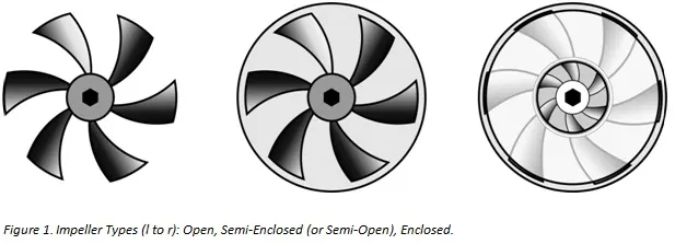
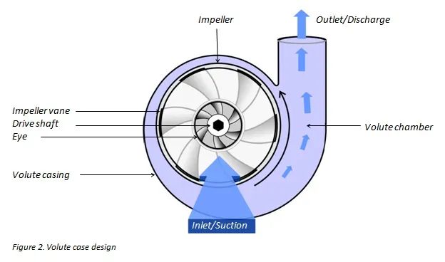
Fluid enters the impeller at its axis (the ‘eye’) and exits along the circumference between the vanes. The impeller, on the opposite side to the eye, is connected through a drive shaft to a motor and rotated at high speed (typically 500-5000rpm). The rotational motion of the impeller accelerates the fluid out through the impeller vanes into the pump casing.
There are two basic designs of pump casing: volute and diffuser. The purpose in both designs is to translate the fluid flow into a controlled discharge at pressure.
In a volute casing, the impeller is offset, effectively creating a curved funnel with an increasing cross-sectional area towards the pump outlet. This design causes the fluid pressure to increase towards the outlet.
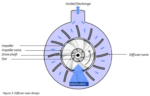
The same basic principle applies to diffuser designs. In this case, the fluid pressure increases as fluid is expelled between a set of stationary vanes surrounding the impeller. Diffuser designs can be tailored for specific applications and can therefore be more efficient. Volute cases are better suited to applications involving entrained solids or high viscosity fluids when it is advantageous to avoid the added constrictions of diffuser vanes. The asymmetry of the volute design can result in greater wear on the impeller and drive shaft.
Classification of Centrifugal Pumps:
1) According to the Working Head:
a) Low Head Pump- Head Limited to 15m
b) Medium Head Pump- Head between 15m and 40m
c) High Head Pump- Head above 40m
2) According to the type of casing:
a) Volute Casing: Volute casing is a spiral diffusion chamber with increasing cross-section towards the discharge end. The increase in area of flow decreases the velocity of flow, thus increasing the static pressure
b) Vortex Casing: In Vortex casing a circular chamber is introduced between the impeller and the casing (Figure (b)). The efficiency of this casing is more compared to the simple volute casing because loss of head due to eddies is reduced considerably.
c) Diffuser Casing: Diffusion casing consists of a ring of stationary vanes called diffuser (figure (c)) provided at the outlet of the impeller. Water leaves the impeller and enters the guide vanes without shock. The area of the fixed vane increases. Therefore, velocity of flow through guide vanes reduces and consequently pressure of liquid increases. The liquid leaving the guide vanes enters the collecting volute of uniform cross-section.
3) According to the number of stages:
4) According to the type of impellers: It can be classified as single suction or double suction impeller.
What is Pressure Ratio?
It is the ratio of Total outlet pressure to Total inlet pressure.
What is Mass Flow Rate?
The mass flow rate is the mass of a liquid substance passing per unit time. In other words, Mass flow rate is defined as the rate of movement of liquid mass through a unit area. The mass flow is directly depended on the density, velocity of the liquid and area of cross-section. It is the movement of mass per unit time. The mass flow is denoted by m and the units in kg/s.
GEOMETRIC SETUP:
1)Open SolidWorks. Create a new part. In the Top Plane, sketch a circle of Radius 0.02m.
2) Without exiting the sketch, draw a concentric circle of radius 0.04m. Join the two circles using the arc tool.
3) Make another such arc and then use circular pattern to make 5 such arcs in the circle. Trim the excess.
4)Extrude this sketch.
5)To make the volute casing, select the Top Plane again and draw a circle of radius 0.045m. Extrude this circle.
(Uncheck Merge with result)
6) To make inlet shaft, select top face of volute and sketch a circle of radius 0.015m. Extrude it.
7)To make outlet shaft, select top plane and draw a tangent to the volute casing. Draw a line parallel to this tangent(distance between the two lines=0.005m) towards the volute. Exit Sketch. Select Features--->Plane. Use the point and line as reference. In the new plane draw a circle of radius 0.005m. Exit sketch and use the swept boss option.
8) Go to the direct editing tab and click on the Add option to combine the outlet shaft with the other components.
9)To make the impeller region, select the top plane. Draw a circle whose radius is greater than that of impeller and lesser than volute casing. Extrude it such that its thickness is less than that of volute casing. Unselect merge result option.
10)Make the part transparent.
11) Using the shell command make the part hollow.
12)Go to the Flow Simulation Tab and create lids at the inlet and outlet.
13)Click on the Wizard option. Enter Project name. Choose SI system of units. Select water as the fluid to be used. Click on Rotation under type of flow. Under Rotation, choose Local Regions Average. Click Finish. Computational Domain is created.
14) Go to Input Data--->Component Control. Unselect Boss-Extrude region 4.
15) Select Boundary Conditions. (Environmental Pressure at Inlet and Outlet Velocit 10m/s at outlet)
16) Insert Surface Goals. (Inlet-average total pressure and mass flow rate. Outlet-average total pressure and mass flow rate)
17) Select Boss-Extrude region 4 as rotating region with angular velocity as 1000 rad/sec.
18)Go to Input Data--->Calculate Control Options. In the dialogue box, select only Iterations. Keep number of iterations as 500.
19)Run the simulation and obtain cut plots for pressure and velocity, as well as Flow trajectory of pressure and velocity (Output Variables for Parametric Study).
20)Run parametric study keeping outlet velocity as Input Variable.
PARAMETRIC STUDY:
RESULTS:
When Outlet Velocity= 10m/s
Cut Plot 1(Pressure):
Cut Plot 2(Velocity):
Flow Trajectory 1(Pressure)
Flow Trajectory 2 (Velocity)
When Outlet Velocity= 14m/s
Cut Plot 1(Pressure):
Cut Plot 2 (Velocity):
Flow Trajectory 1 (Pressure):
Flow Trajectory 2(Velocity):
When Outlet Velocity= 18m/s
Cut Plot 1(Pressure):
Cut Plot 2 (Velocity):
Flow Trajectory 1 (Pressure):
Flow Trajectory 2 (Velocity):
When Outlet Velocity= 22m/s
Cut Plot 1(Pressure):
Cut Plot 2 (Velocity):
Flow Trajectory 1(Pressure):
Flow Trajectory 2 (Velocity):
When Outlet Velocity= 26m/s
Cut Plot 1(Pressure):
Cut Plot 2 (Velocity):
Flow Trajectory 1 (Pressure):
Flow Trajectory 2(Velocity):
When Outlet Velocity= 30m/s
Cut Plot 1(Pressure):
Cut Plot 2(Velocity)
Flow Trajectory 1(Pressure):
Flow Trajectory 2(Velocity):
PLOT: Pressure Ratio vs Mass Flow Rate Outlet
Taking Mass Flow rate as positive,
CONCLUSION:
1)It is observed that as outlet velocity increases, the mass flow rate also increases (there are some small sinusoidal variations after sudden increase).
2)Pressure Ratio is high for low velocities and low for high velocities.
3)The negative sign for mass flow rate indicates it is at outlet.
4)The variation of Pressure Ratio with Mass Flow Rate (Outlet) is not linear but sinusoidal. Pressure Ratio first decreases, then increases, then remains constant for some time, then decreases and finally increases.
SOURCES OF ERROR:
1)Innaccurate Dimensions.
REFERENCES:
https://www.michael-smith-engineers.co.uk/resources/useful-info/centrifugal-pumps