CASE STUDY OF DIFFERENT METHODS OF MID SURFACE EXTRACTION & MESHING FOR A GIVEN SHEET PANEL
AIM:
To compare the results on different mesh generation & mid surface extraction method for a given sheet metal component. Also to give a detailed report stating that which method gives best mesh flow & which would be the best way.
GIVEN DATA:
- Cad model
- Quality Criteria
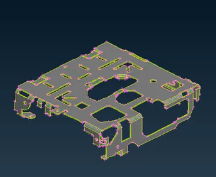
Figure 1 - CAD MODEL
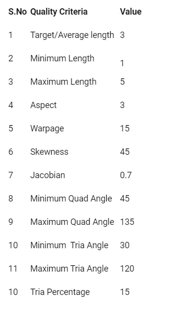
Figure 2 - Given Quality Criteria
CASE STUDY:
To compare the results on different mesh generation & mid surface extraction. I had gone with three case studies for this challenge. They are,
- Case study - 1: Midsurface Extraction - Skin method; Mesh generation - Batch mesh method (Auto mesh).
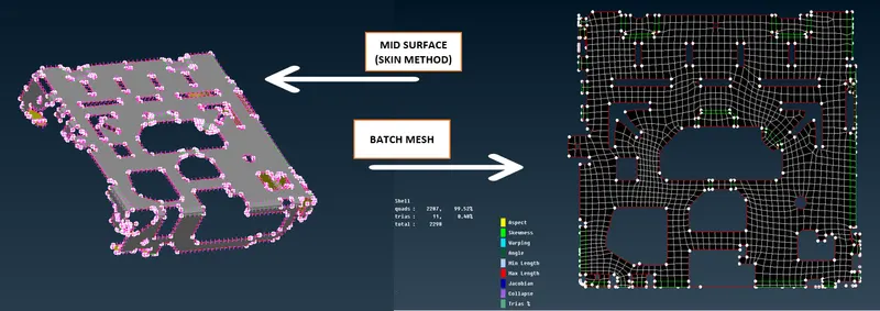
Figure 3 - SkIN MID SURFACE & BATCH MESH
- Case study - 2: Midsurface Extraction - Casting method; Mesh generation- Casting method (Auto mesh).
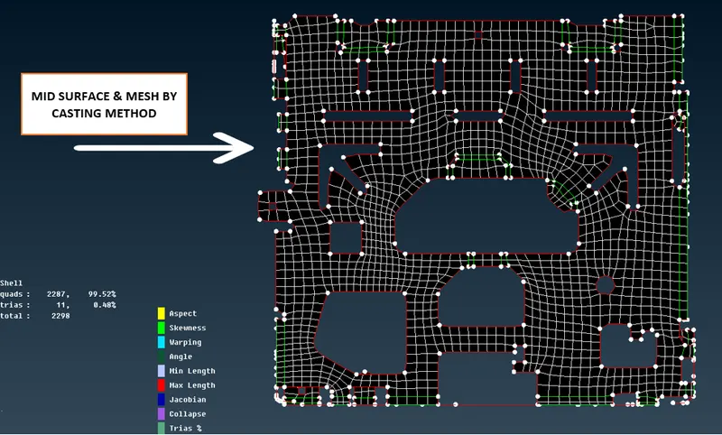
Figure 4 - MID & MESH BY CASTING METHOD
- Case study - 3: Midsurface Extraction - Offset method; Mesh generation - Best mesh, Spot mesh, map mesh methods (Manual mesh method).
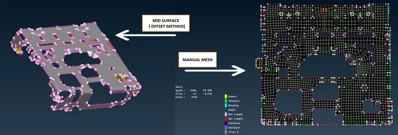
Figure 5 - MID BY OFFSET & MANUAL MESHING METHOD
Before performing the case studies, the given qulaity criteria & mesh parameters are entered and saved by using GUI settings. [Go to Tools --> settings --> save all]
CASE STUDY 1:
Midsurface Extraction - Skin method (Auto mid); Mesh generation - Batch mesh method (Auto mesh):
- Once the topo & geometry cleanup done.
- As per case study 1 the Mid surface is generated by skin method.
- In Skin method the PID will generated automatically.
- PROCEDURE TO EXTRACT MID SURFACE - BY USING SKIN METHOD:
- Step-1: Go to ---> Faces ---> Mid surface ---> Skin
- Step-2: Edit area Tab will pop-up. Check for the colours as Middle - blue, Top - green, Bottom - Red. After confirming the check middle click on mouse. Now the skin - mid surface would generated with PID assinged.
- PROCEDURE TO EXTRACT MID SURFACE - BY USING SKIN METHOD:
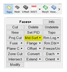
Figure 6 - STEP 1 (PROCEDURE TO EXTRACT MID SURFACE - BY USING SKIN METHOD)
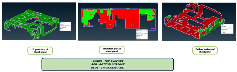
Figure 7 - STEP 2 (PROCEDURE TO EXTRACT MID SURFACE - BY USING SKIN METHOD)
- Once the mid extracted, Mesh has to be performed. For this case Batch mesh had been performed.
- PROCEDURE TO PERFORM BATCH MESH:
- Step-1: Click on Batch mesh
- Step-2: Batch mesh manager will pop-up. Go to New --> Mesh scenerio. The mesh scenerio will be look as shown in below figure
- Step-3: To open contents of meshing scenerio click the content as shown in below figure. Change the parts to PID & slect the PID which has to be batch meshed and click the green arrow to bring the selected PID from left to right and then click OK.
- Step-4: Once Step 3 completed. It will automatically go to batch mesh manager there click RUN to perform mesh for the selected PID. Once the Run completed the mesh would be deployed to the selected PID. NOW the status will be changed from empty to completed.
- PROCEDURE TO PERFORM BATCH MESH:
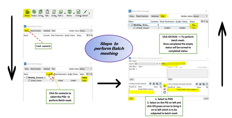
Figure 8 - STEPS TO PERFORM BATCH MESH
- Once the Batch mesh algorithm completed its run. we will get the component by mesh deployed
- Since it is an Automated algorithm to perform mesh there is a chance of incorrect capture on the features. As an Engineer its our duty to check those things and to perform some changes to capture the features correctly.
- If there is some off elements found have to solve/fix those off elements with the help of reconstruct, smooth, split, swap options.
- Also to consider the trias by eliminating if possible, opposite tria to be eliminated, the trias near the holes or free edges should be swapped.
CASE STUDY 2:
Midsurface Extraction & Mesh generation by Casting method (Auto mid & Auto mesh):
- Once the topo & geometry cleanup done.
- As per case study -2, Mid & mesh has to be performed by casting method.
- PROCEDURE TO EXTRACT MID SURFACE & DEPLOY MESHING - BY USING CASTING METHOD:
- Step-1: Go to Topo ---> Faces ---> Mid surface ---> Casting.
- Step-2: Enter the minimum thickness value then click OK.
- PROCEDURE TO EXTRACT MID SURFACE & DEPLOY MESHING - BY USING CASTING METHOD:
Figure 9 - STEP 1 (PROCEDURE TO EXTRACT MID SURFACE & DEPLOY MESHING - BY USING CASTING METHOD)
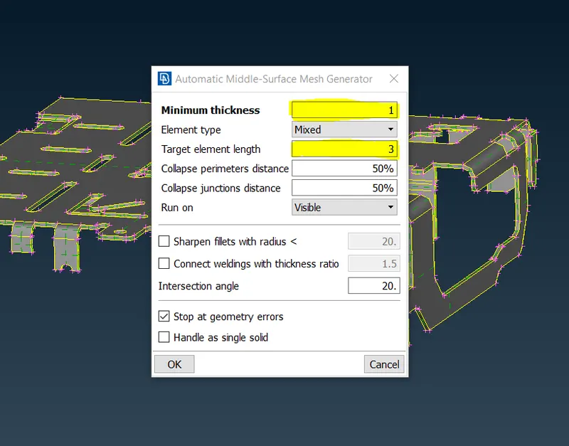
Figure 10 - STEP 2 (PROCEDURE TO EXTRACT MID SURFACE & DEPLOY MESHING - BY USING CASTING METHOD)
- The Mid & the mesh will be generated with automatically assigned thickness as well as PID.
- Again, Since it is an Automated algorithm to perform mesh there is a chance of incorrect capture on the features. As an Engineer its our duty to check those things and to perform some changes to capture the features correctly.
- If there is some off elements found have to solve/fix those off elements with the help of reconstruct, smooth, split, swap options.
- Also to consider the trias by eliminating if possible, opposite tria to be eliminated, the trias near the holes or free edges should be swapped.
CASE STUDY 3:
Midsurface Extraction (Offset) & Mesh generation by Manual method (Manual mid & manual mesh deployment):
- Once the topo & geometry cleanup done.
- As per case study -3, Mid & mesh has to be performed manually.
- Before taking mid surface, check with the orientation or Go to Topo --> Faces --> Orient ---> Visible/Auto
- It is neccessary to measure a thickness of the component since the value is needed while offseting as it is a manual method.
- Extract a mid surface by using OFFSET.
- PROCEDURE TO EXTRACT MID SURFACE USING - OFFSET:
- Step-1: Go to Topo ---> Faces ---> Mid surface ---> Offset.
- Step-2: Enter the offset value and middle click on mouse. Now the mid would be generated.
- Step-3: Since it is a manual method, the PID and thickness has to assign manually. For that Go to Topo --> Faces --> Set PID --> Create new -->Then after creation right click on the created PID ---> Apply ---> Select the mid surface generated. To define thickness Edit and Fill the Thickness value in coloumn T.
- PROCEDURE TO EXTRACT MID SURFACE USING - OFFSET:
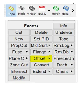
Figure 11 - STEP 1 (PROCEDURE TO EXTRACT MID SURFACE USING - OFFSET)
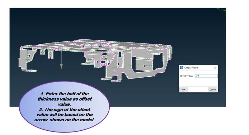
Figure 12 - STEP 2 (PROCEDURE TO EXTRACT MID SURFACE USING - OFFSET)
- PROCEDURE TO DEPLOY MESH MANUALLY:
- Best practices has to be followed while deploying manual mesh.
- Using Cut (Plane cut / parametric cut) split the PID into macro areas so that it is easy to get a good mesh flow. [GO to TOPO --> Faces --> cut]
- Use slide [GO TO MESH --> perimeter --> Slide] to make the cons of holes parallel. Especial for square holes.
- Check with perimeter number for the holes which has to be always an even number. If not change the number to even. [Go to mesh --> perimeter --> Number --> middle click on mouse]
- Mark the nodes of the holes to avoid distortion while deploying connections.
- Capture the features at its peak point.
- We can use either best mesh, spot mesh, or map mesh as all these run in different algorithm. Here I had gone with BEST mesh.
- If there is some off elements found have to solve/fix those off elements with the help of reconstruct, smooth, split, swap options.
- Also to consider the trias by eliminating if possible, opposite tria to be eliminated, the trias near the holes or free edges should be swapped.
MESH (Before & after mesh rework):
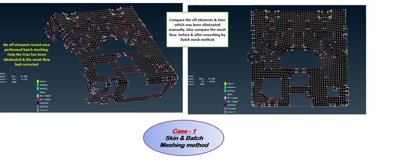
Figure 13 - Before & after mesh rework for Case-1 Skin & batch mesh method
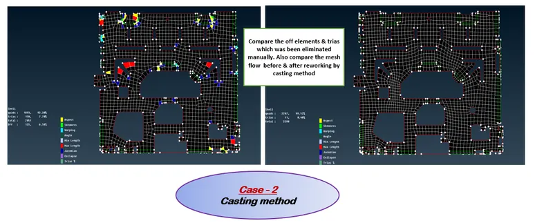
Figure 14 - Before & after mesh rework for Case-2 Casting method
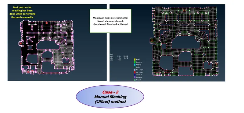
Figure 15 - Before & after mesh rework for Case-3 Offset & manual mesh method
ADVANTAGES & DISADVANTAGES BETWEEN THIS THREE CASES:
- Case 1 - Skin Mid & Batch mesh method:
- Advantages:
- Midsurface by skin -
- Time saving to extract the mid surface for a component having uniform thickness.
- Generates PID automatically.
- Batch mesh -
- Automatically runs the mesh using batch mesh manager. So it reduces the time involved in manual meshing.
- Work for an engineer made easy.
- Can erase the mesh in some macros and we can slide the holes parallel to the cons and re mesh those macros to achieve better flow there.
- Midsurface by skin -
- Disadvantages:
- Midsurface by skin -
- Since it is a time saving method to extract the mid surface it is limited only to sheet metal component having uniform thickness. Varying thickness - plastic components are not suitable for this method.
- Batch mesh -
- Although it reduces the time, Some times it cracks inbetween the running the batch mesh algorithm.
- Some holes may not be parallel to the cons. So have to erase the mesh on particular macros and to do the best practice on that macros alone.
- Some features failed to capture well.
- Midsurface by skin -
- Advantages:
- Case 2 - Casting method:
- Advantages:
- This method automatically extract the mid surface & deploys mesh on the mid automatically by giving the minimum thickness value.
- Suits for both components having uniform thickness & varying thickness.
- Work for an engineer made easy.
- Disadvantages:
- As per batch mesh rework has to be performed to get better mesh flow.
- Some features failed to capture well.
- Some holes may not be parallel to the cons.
- Unable to erase the mesh on macros to rework.
- Advantages:
- Case 3 - Mid by offset & Manual meshing method:
- Advantages:
- Midsurface by Offset -
- Since it is a manual method to extract midsurface, This offset method is very useful to extract mid for plastic parts or varying thickness component.
- Manual Mesh -
- Gives better mesh flow and best results.
- Midsurface by Offset -
- Disadvantages:
- Midsurface by Offset -
- Time taken will be more.
- Manual Mesh -
- As it gives better mesh flow, More pre work has to be done to follow the best practices.
- Time taken will also be more since we will be meshing manually the macros seperately.
- Midsurface by Offset -
- Advantages:
MESH FLOW
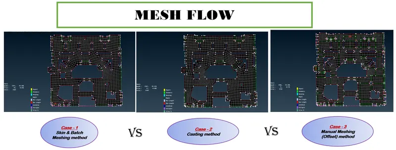
Figure 16 - MESH FLOW OF THREE CASES
ELEMENTS DETAIL
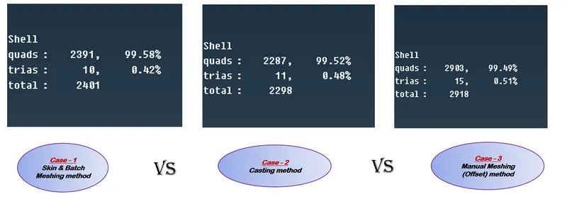
Figure 17 - ELEMENT DETAILS OF THREE CASES
RESULT
While comparing these three cases on different methods for mid extraction & meshing Manual meshing gives better result as a whole since we have worked manually. In manual meshing, meshes are deployed macros by macros taking more time also the feature capture as well as holes are captured correctly.
But this sheet metal component is a simple part. Here batch mesh also works quite good and gives better results and better mesh flow on reworking on mesh. The holes captured wrongly can be corrected by erasing the mesh on a particular macros and can be remesh those macros alone.
In casting method, we can not slid the hole parallel to the cons as done in batch mesh method. The holes got distorted & the mesh for that macros unable to erase for capturing the holes correctly.
So as a result, Manual meshing & Batch meshing gives better mesh flow & better results
CONCLUSION
The results on different mesh generation & mid surface extraction method for a given sheet metal component has compared successfully. Also a detailed report had stated that which method gives best mesh flow & which would be the best way.
LEARNING OUTCOMES
At the end of this challenge, I can able to
Identify the suitable methods of mid surface extraction & mesh generation for a given component by considering the project time, Component complexity, etc.