CAD Cleanup and Advance Meshing of a Car Model with Wind Tunnel
CAD Cleanup and Advance Meshing of a Car Model with Wind Tunnel
Aim :
1. To Perform the CAD Cleanup of the Car model provided based on external aerodynamic analysis .
2.Create the wind tunnel to define fluid domain and perform Tyre crushing
3. Making The car model and the Wind tunnel free of any errors
4.To perform surface meshing on car and wind tunnel for external aerodynamic Analysis
Geometry Link : Please click here to find the geometry for the car model
https://drive.google.com/file/d/12NSEXI_pBmxu8hBqKiHD_kh9MUnYpSrW/view?usp=share_link
Procedure :
1.Units are in mm
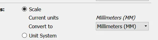
2.Resolution is proper , we need not to change any resolution
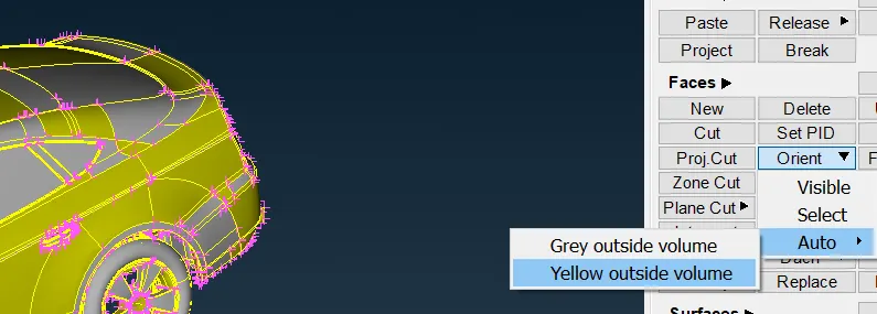
3. Orientation set as yellow outside volume
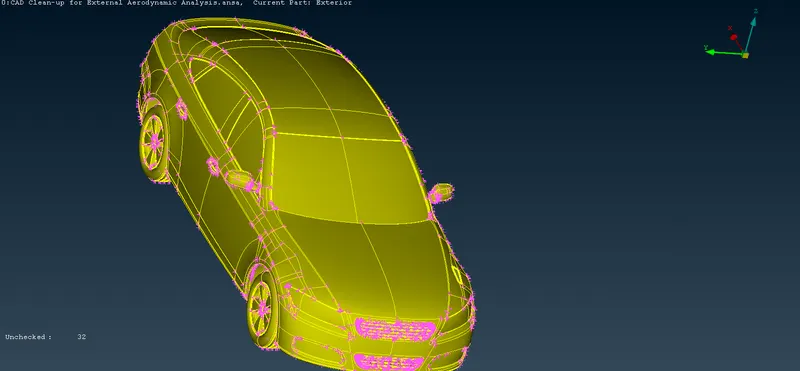
4. As we are going to perform externel aerodynamic analysis . We will not be including internal surfaces like cabbin
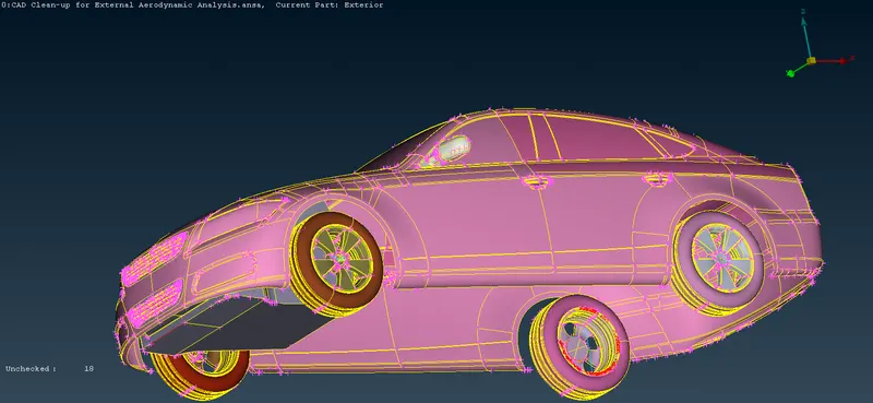
5.We are going to hide the unnecessary parts which are not symmetric and delete half of the part of car model and will do geometery cleanup of half of the geometry and do mirror operation of the same and replicate the same .
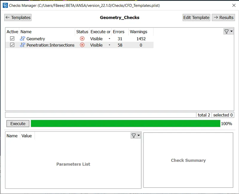
6.Performing initial error check
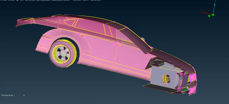
7.Hiding the unsymmetric parts
Underbody ,Exhaust system , Engine
8.Providing the half division using plane cut
9.Assigning a seperate PID for the bumper as it is not symmetric
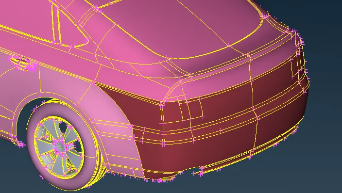
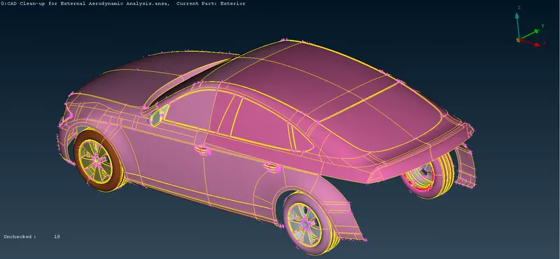
10.Half of the portion of the car has to be deleted which has errors more
11.Error check 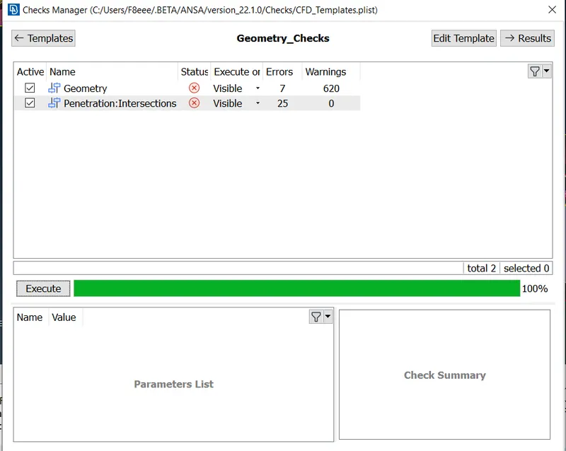
12.We will be working on component basis starting from mirror
13.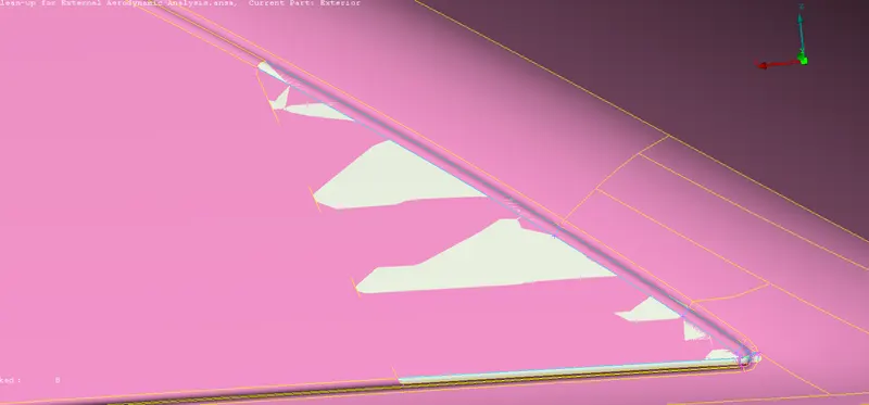
this mirror part is not uniform so we will be projecting that part's cons to the near by surfaces
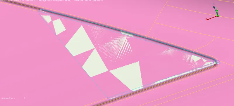
Now it became fine
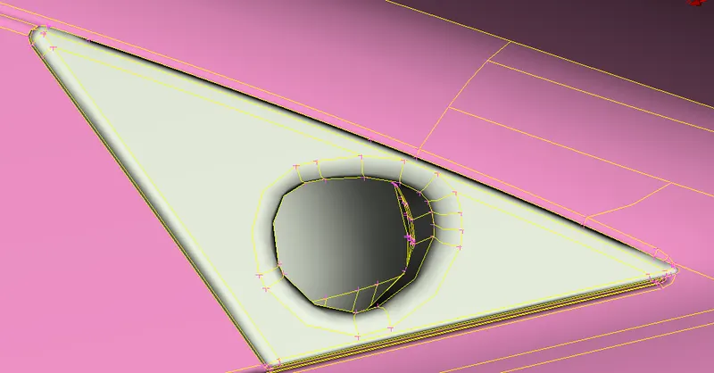
if we can closely observe there are some gaps between faces of mirror and external body
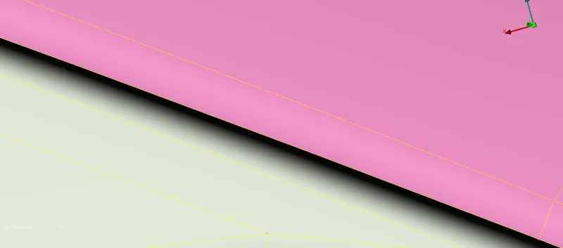
14. Our geometry should be smooth , it should not be very sharp . If it is sharp flow around that would be trapped in that sharp edges ,
so where there are gaps between surfaces those surfaces have been deleted and new surfaces are created there
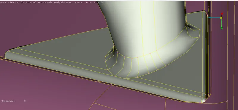
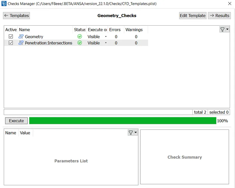
15.Error check on mirror part :
In between there are some gaps in the cad model which may further lead to formation of convex cons . To prevent that , additional care is taken. and Stitching operation has been performed to make the mirror part and the near by region is error free.
16. Cleaning of Tyres:
i.car tyres have been isolated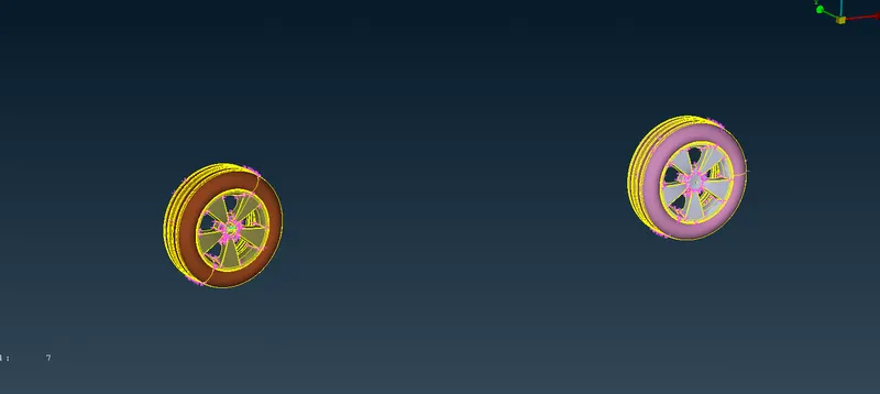
ii. In order to clean the geometry of the tyres , we first clean one of the tyre geometry and after that we will proceed with pasting the that geometry .
iii. To copy and proceed further, we will be wanting one reference point .
We will be creating one 3D points on COG
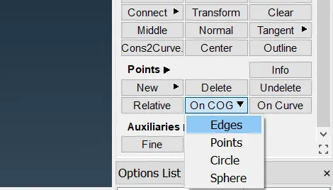
3D Point has been created 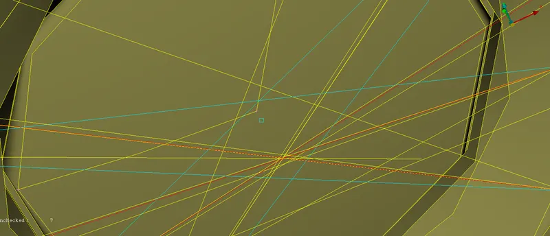
In the same manner it has been done for the second tyre also 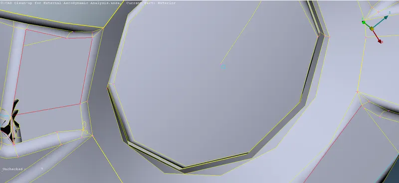
now the second tyre has been detailed .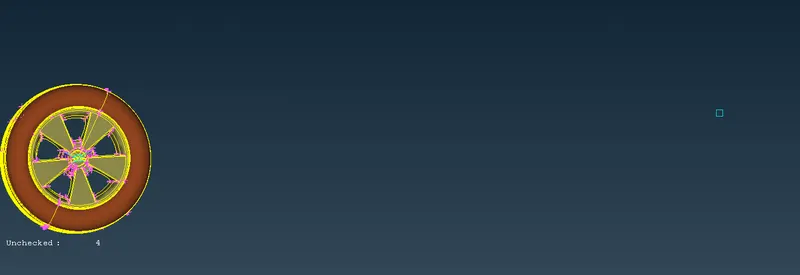
Now we can start the cleaning of the tyre
As we are cleaning this for external aerodynamics , we are not going to be using the faces which are in the internal part of the tyre . we study the PID and will remove the PID which are not going to interract with the flow 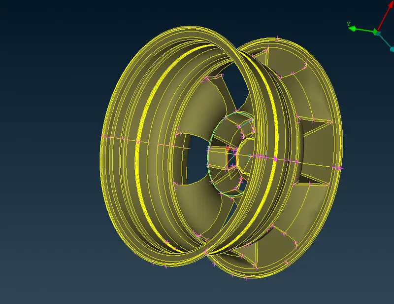
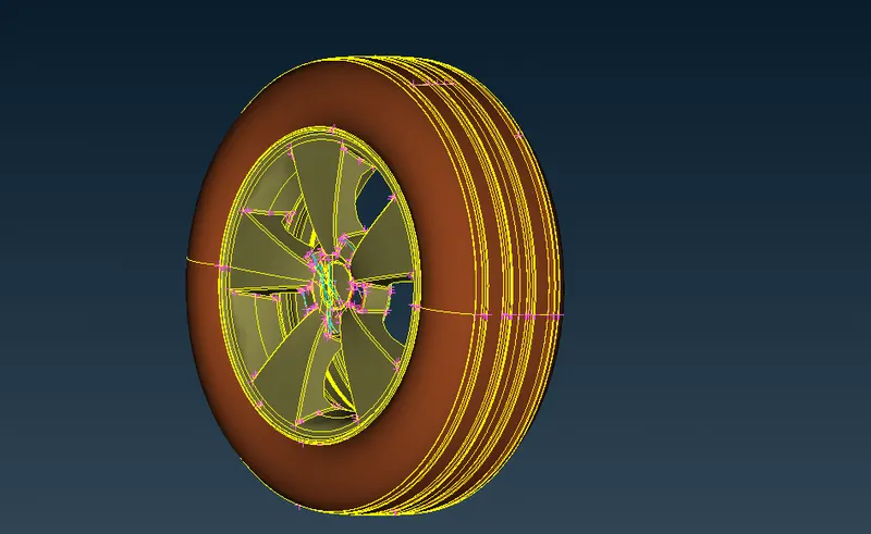
Unchecked faces has to be deleted
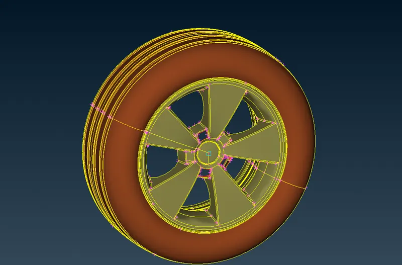
Unchecked faces formed due to the incomplete CONS and those can not be shown when switched from wireframe mode to Shadow mode
if we can closely observe the resolution of the tyre is not adequate that needs to be changed
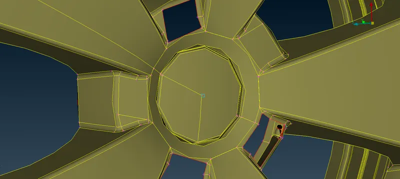
Unwanted faces has been removed and face has been created 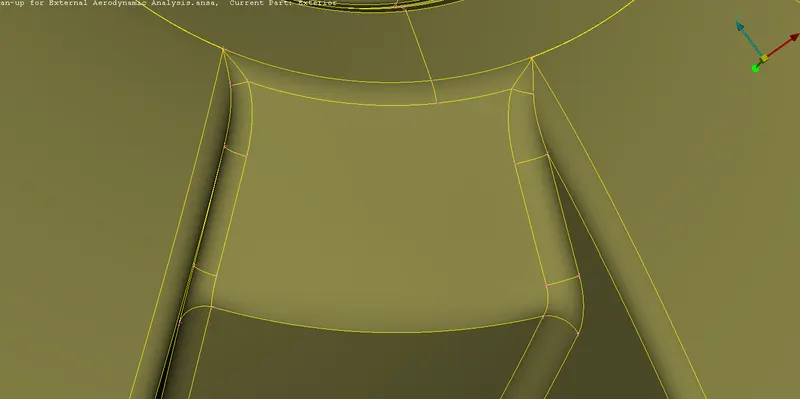
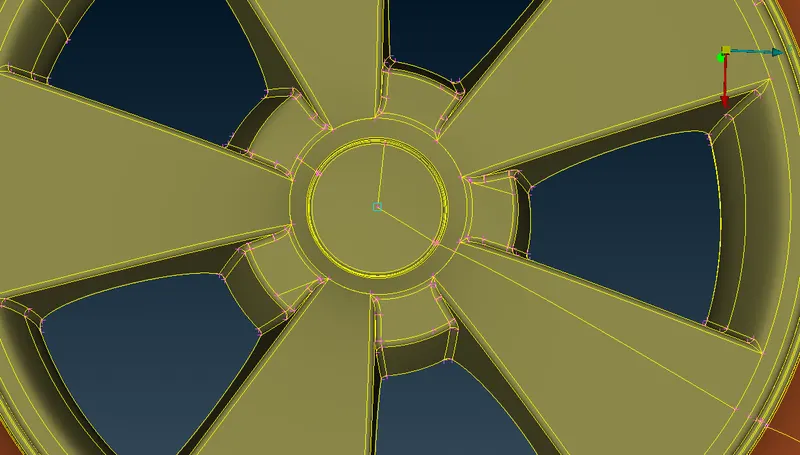
there are some gaps which are formed here we have to clean them
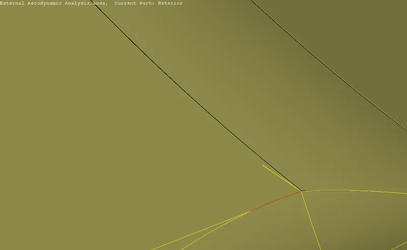
Back side part of the tyre mode has to be closed
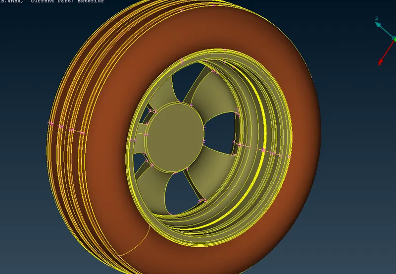
check on the tyre at the moment 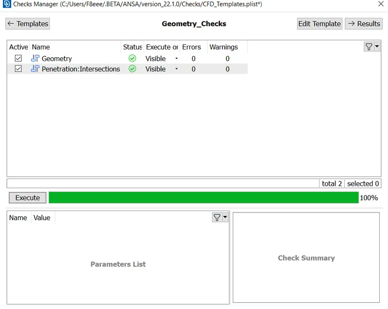
when ever there are some unsolved intersection errors or convex cons , we must try deleting the neighbour face and recreating them again
Now we have to mirror the tyres
we have to select copy from transform option 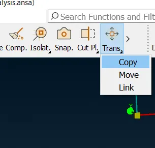
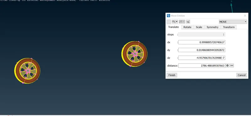
Error check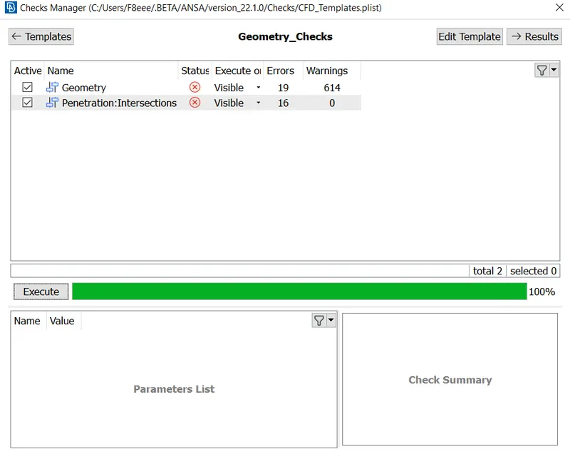
Cleaning of Grill :
unnecessary Hot points have been deleted 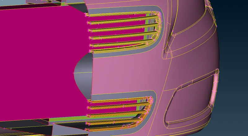
using feature option , overlapped faces between the grill have been deleted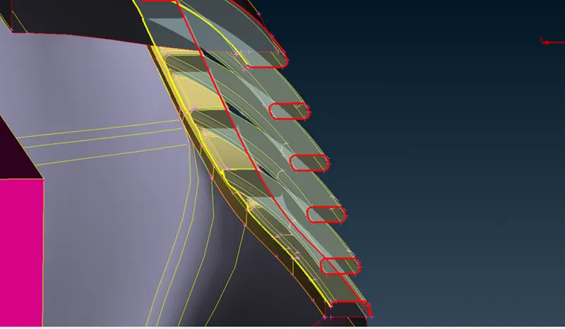
grill face have been closed without any gaps 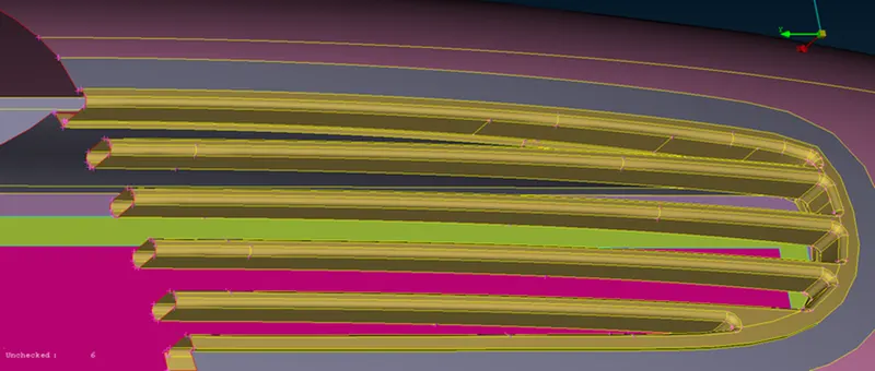
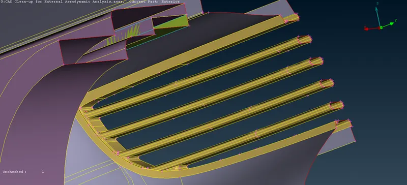
same kind of procedure we have to follow for the second grill as well . We will be deleting the faces which are not interrracting with the flow .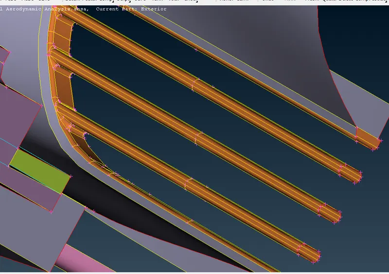
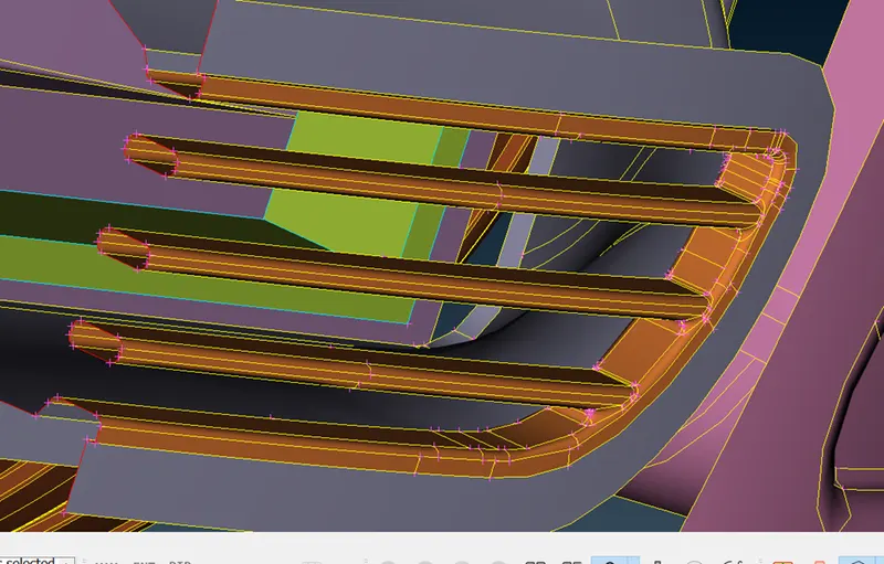
Isolating grill faces and checking for errors:
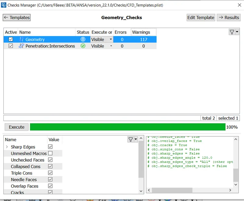
some single CONS are formed because we deleted half of the part . And Convex cons cleared as follows:
Some sharp faces are there which are causing concave cons . Those sharp faces will not be encouraged and
those can affect the flow around that region and in fact affect the analysis and capturing of physics of that particular region .
By projecting cons in parallel and creating faces parallelly we can create sharpless faces
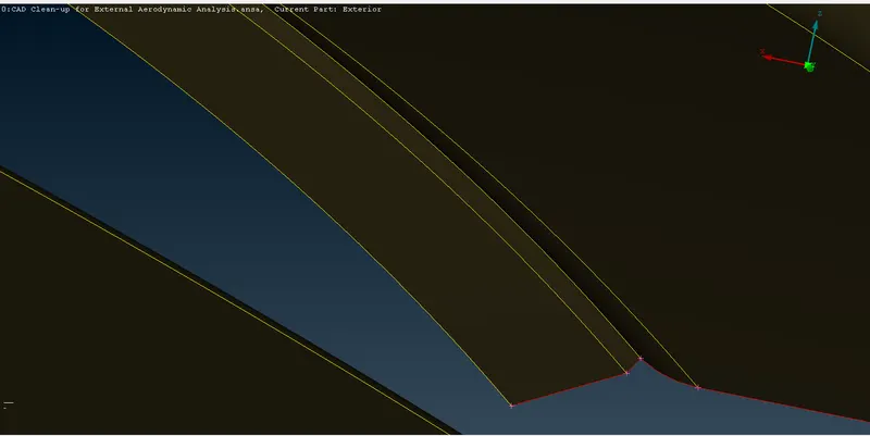
these are the remained convex cons
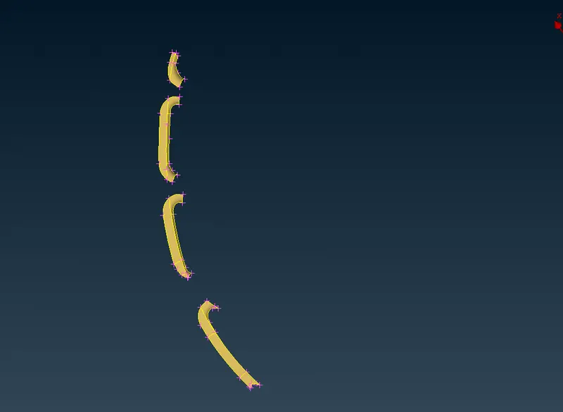
one region has been re adjusted to create the error free parts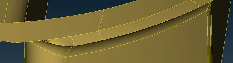
Second region has been modified like this to reduce convex cons
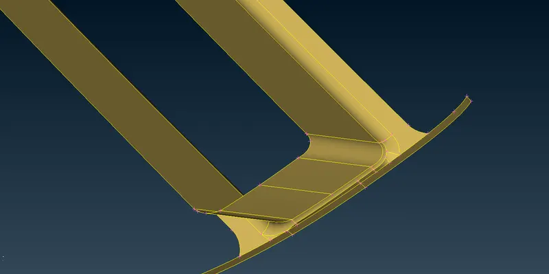
After removing the all of sharp edges now mirror became free of errors 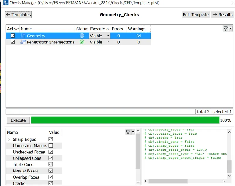
Now that we have cleared mirror we can go to further parts.
Radiator casing and cooling pack cleanup :
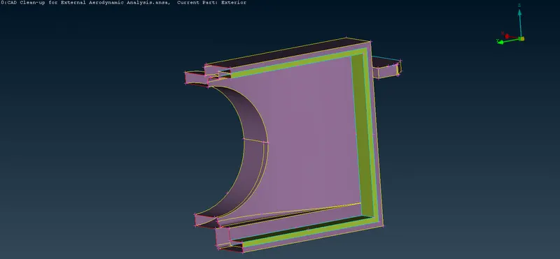
We are going to delete few faces which are not going to interrract with the flow:
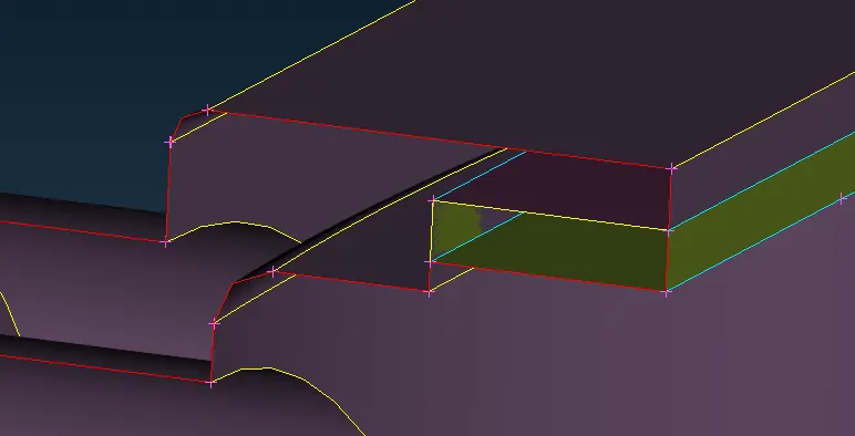
Triple cons must have to be checked so that no required face be deleted . Faces whcih can be interracted with the flow can be kept
After the cleanup of casing and removing unwanted surfaces and doing necessary changes the error check has been performed 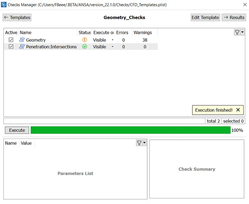
These triple CONS can not be avoided for cooling pack and radiator casing 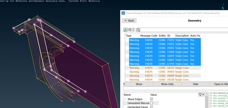
Shroud Cleanup :
Shroud supports on cooling pack casing . So there will be intersection error as we can verify here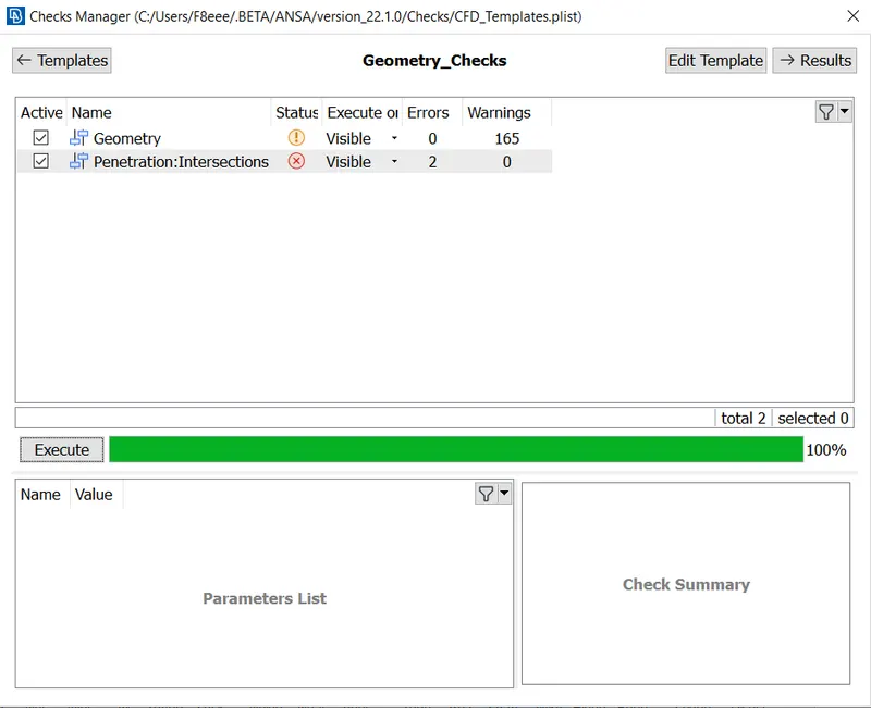
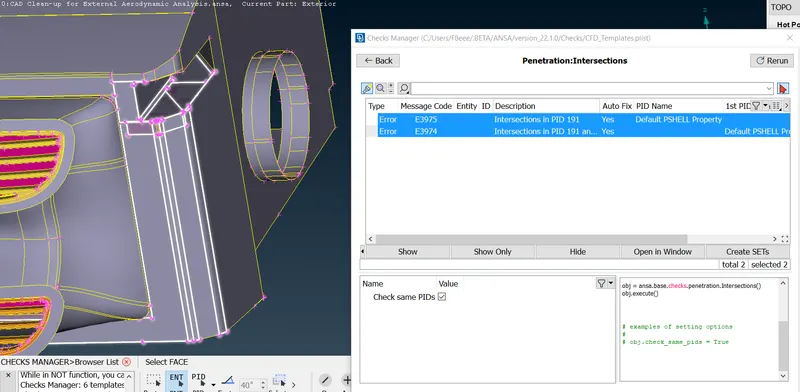
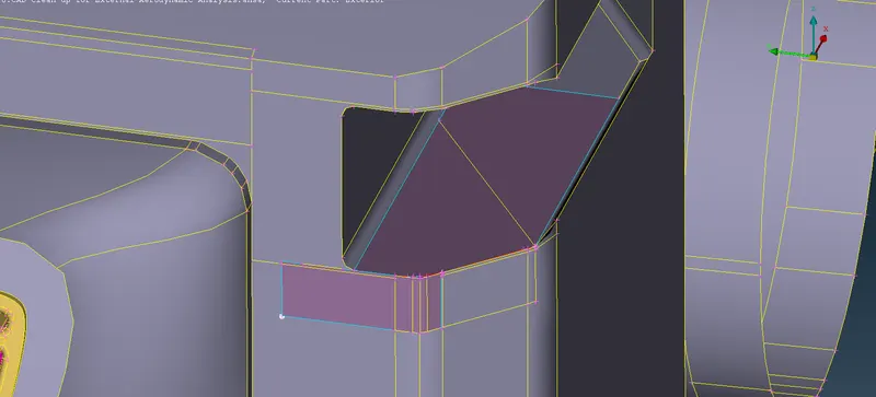
Using intersect option with PIDs intersection part between cooling case and shroud has been found and as we can see from the above picture
and unwanted faces can be deleted and in remaining areas can be adjusted with filled using cons option 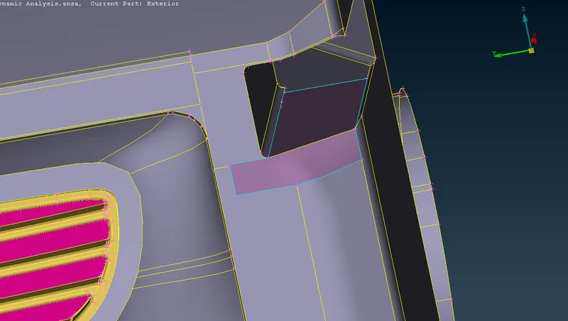
Error check has been performed 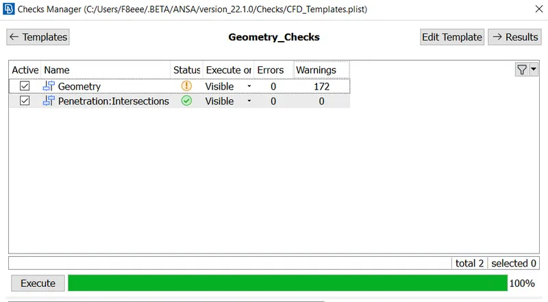
All of the single CONS are formed out side of our targetting region 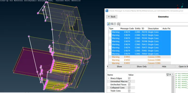
This duct is not going to interract with the flow so it can be deleted
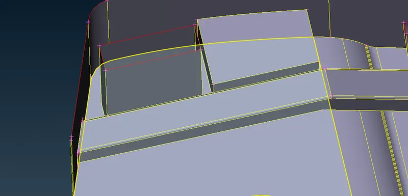
After all of the cleanup and succesfull adition of faces error check has been performed 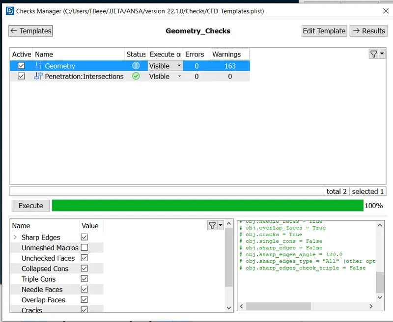
Shroud and cooling pack cleaned succesfully .
Till now geometry cleanup for the parts which are symmetrical have been done . Now its time to move on to work on parts which are not symmetrical .
Cleanup of unsymmetrical parts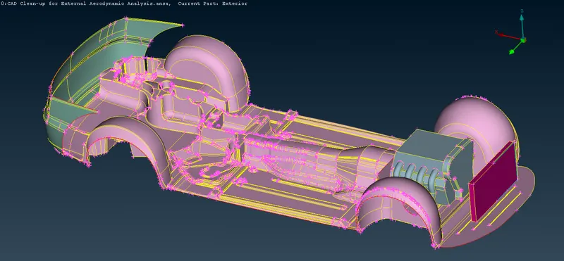
Engine Cleanup :
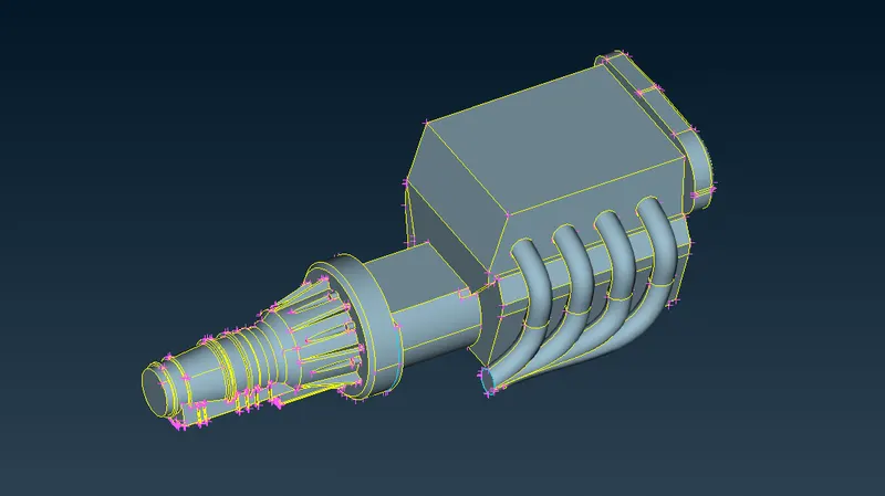
Initial error check :
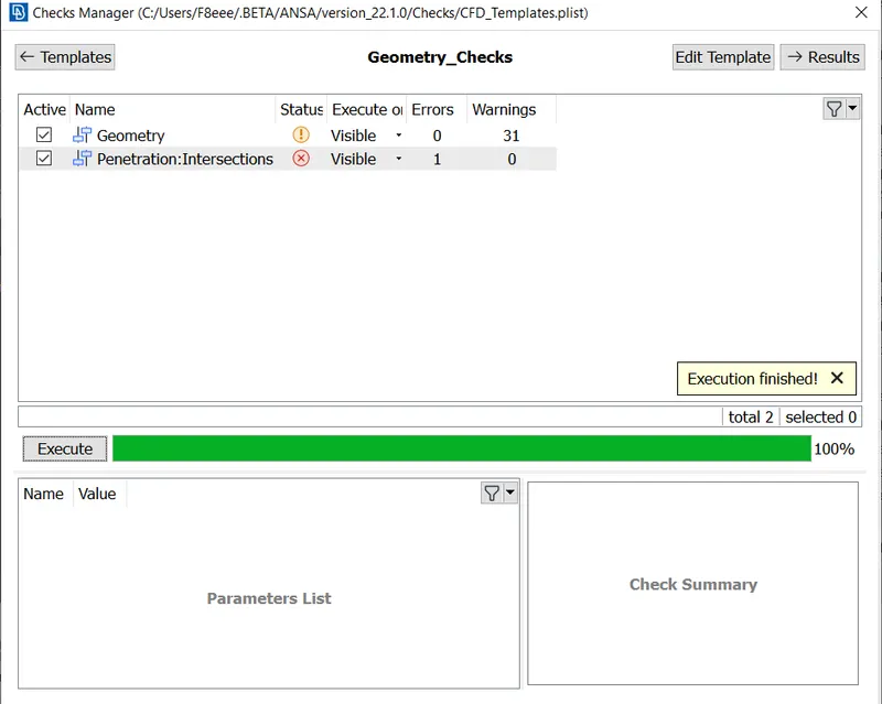
here we can see that one intersection is forming due to closing of one component . That can be deleted as it is not going to be interracting with the flow "
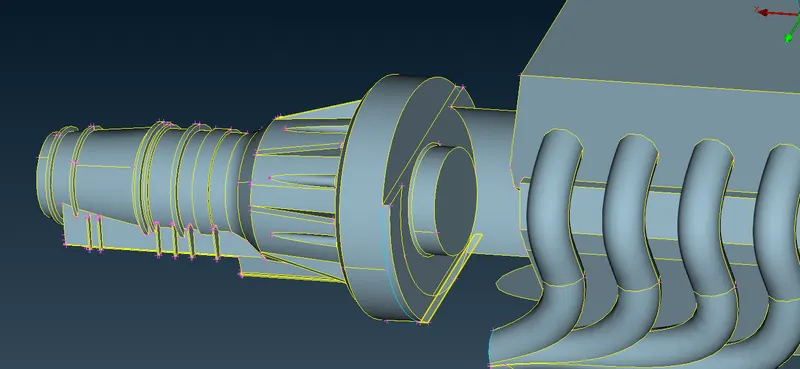
where ever we are not able to define the boundaries properly we cam use the intersect option there.
error check :
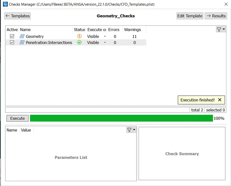
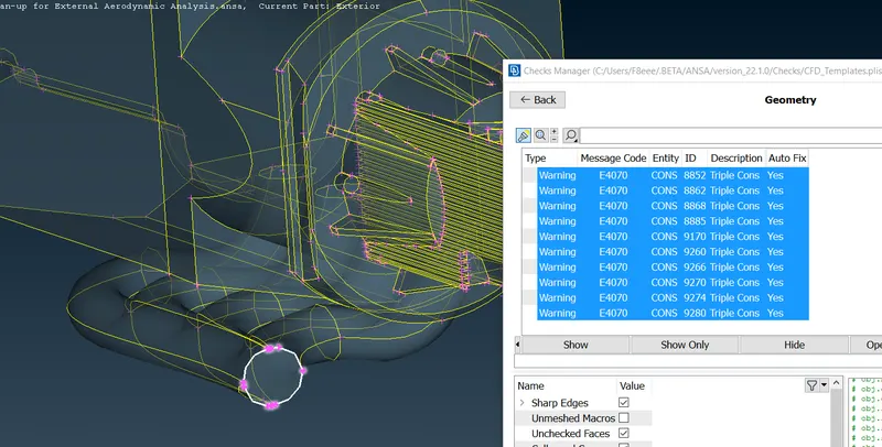
these are the places where are the triple CONS are there
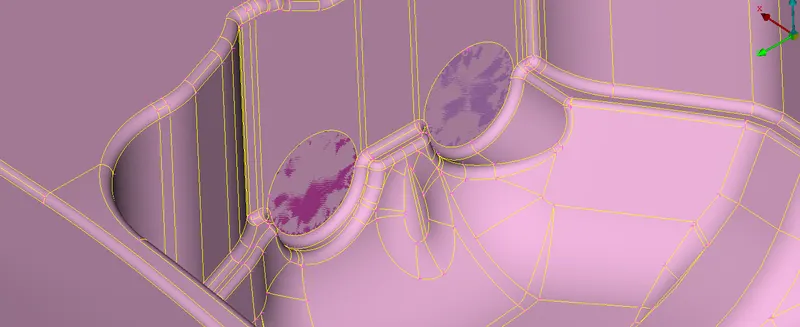
Cleanup of Exhaust System :
If we can closely observe the exhaust system , it is kind of closed here. It has to be openeed .
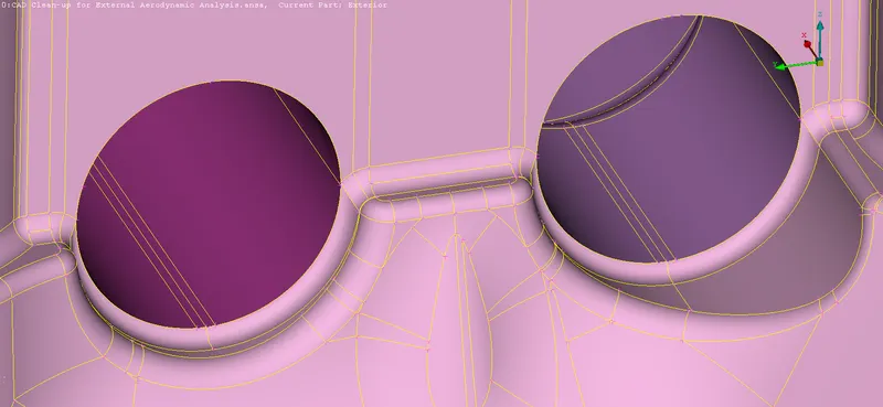
those exhaust ports have been made as open
Mirroring :
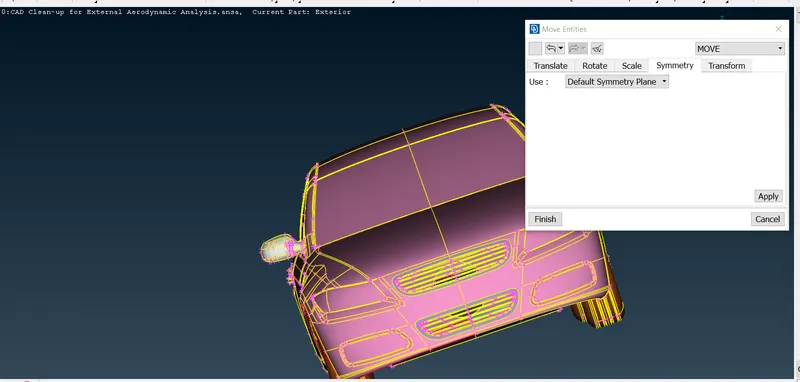
Now it got mirrored :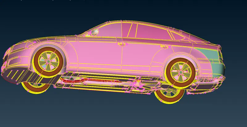
Wind Tunnel Creation :
from the front face of the car, we will have to create a relative point with a distance of 3*l
by taking that reference point we will have to create a face at the bottom to create relative points on both sides from the middle this will help to create all faces of the wind tunnel wind tunnel.
by using these relative points we will have creat a relative point on the rear side of the car and connet all this with the curves
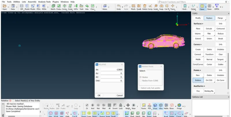
Use curves or lines for the bottom surface :
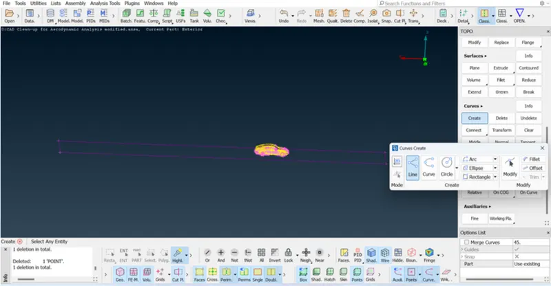
Offset the bottom face and create the top face of the wind tunnel :
create a new face by using the curve we have created and delete the reference curves. and do the offset and provide the distance by selecting the direction. it will create a top face of the wind tunnel
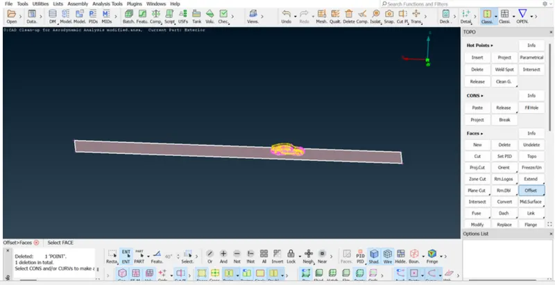
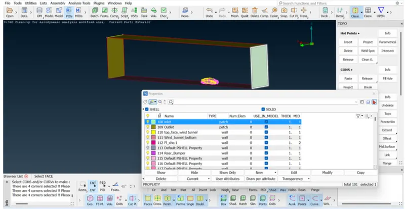
Creating faces and names of the wind tunnel :
We will have to create a pid of the wind tunnel base don the faces and its location to identify easily while assigning the boundary conditions.
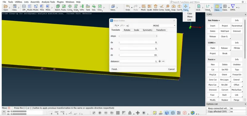
Wind tunnel move :
we will have to define compression between the tires and the bottom face of the wind tunnel by projecting the tires with the bottom face of the wind tunnel by moving 10 mm height of the wind tunnel
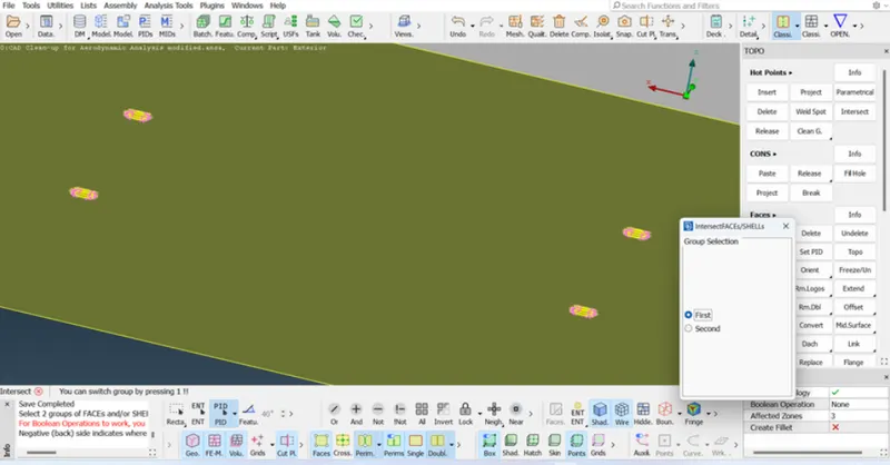
Intersecting the bottom surface of the wind tunnel and the tyres :
Intersecting the bottom face of the wind tunnel with all thtyres and remove the intersections
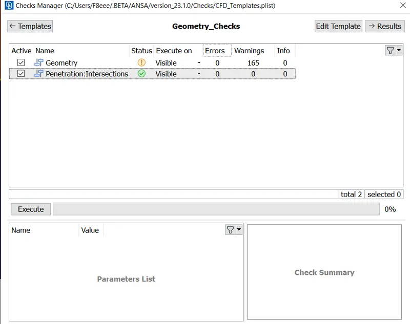
this is how the final checks of the geometry errors.
by doing all the geometry cleanup up the process we were able to remove all the errors
Meshing :
Procedure :
1. For meshing we have to ensure that there are not any geometrical errors
2. We will decide target length based on the smallest possible distance between two CONS.
3.The actual approach for this kind or any kind of big geometry simplification followed by meshing is we just delete the half part and clean the other part and mesh(Provided the geometry is symmetric )
4.For this particular model we have car and a windtunnel we start meshing with tyres
5. Meshing of Tyres :- We take Auto CFD optiion for spacing with a maximum length as 2mm and minimum length as 0.8mm considering the computational resource available
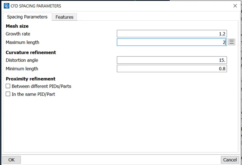
same has been given for the macros also .
6.We are going to use CFD Meshing
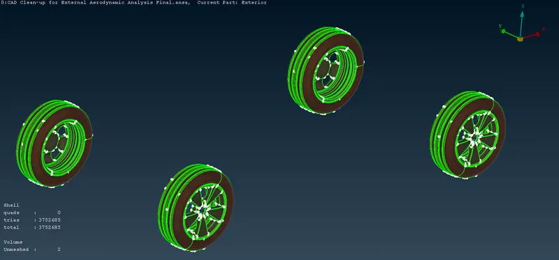
7.Off elements were improved :
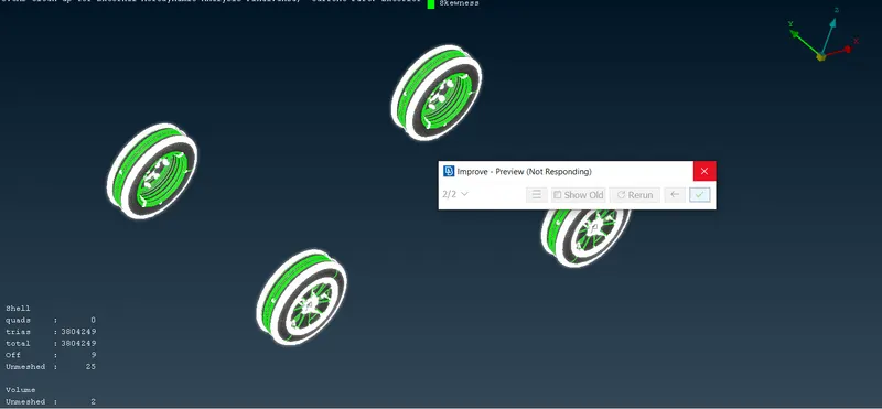
those off elements were close to 3 after that process
now that tyres were frozen
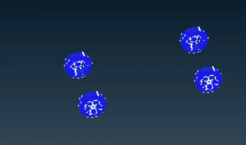
8.Meshing of grills :
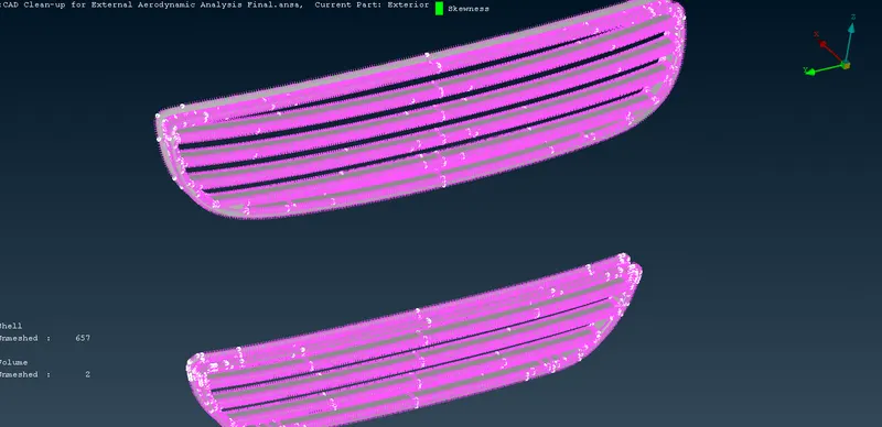
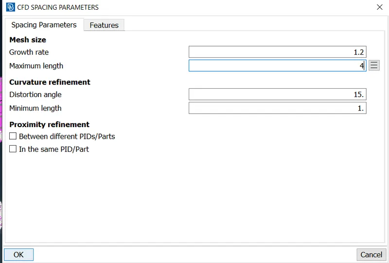
According to the size of the grills we can conclude that maximum and minimum length of autospacing are 4mm and 1 mm respectively.
Auto CFD spacing for Paremeter and macros were given in this manner :
CFD Mesh Generation :
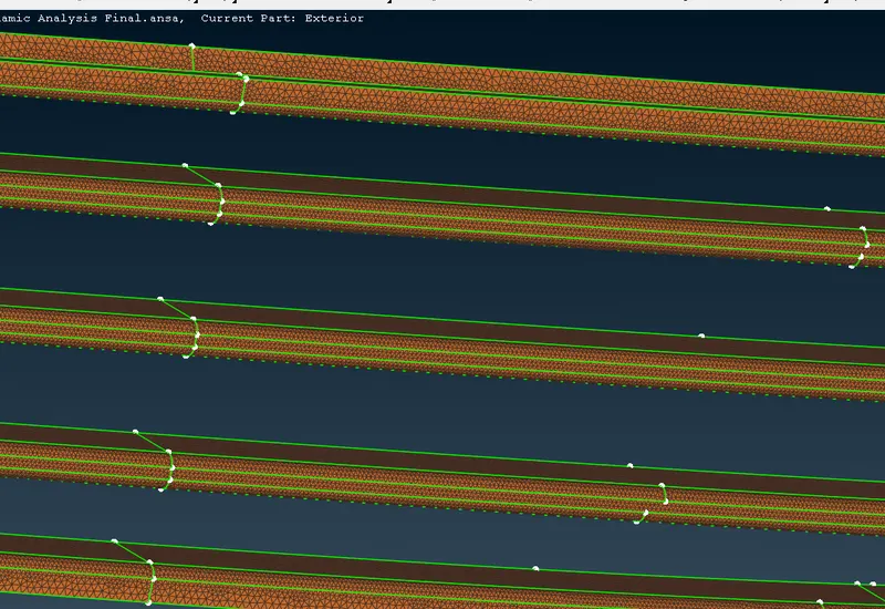
9.Now the grill part has also to be freezed and now we move on to the other part :
For arts other than grills tyres we can go with a range of 8 -20 mm as Auto CFD Spacing
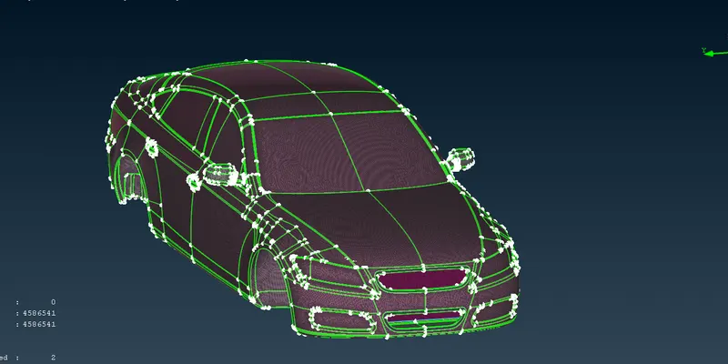
10. now meshing the wind tunnel :
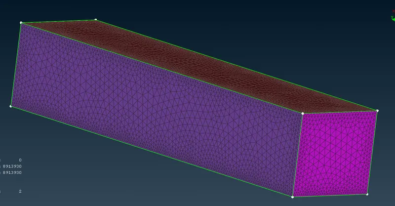
For wind tunnel we can create mannual spacing . with minimum number of cells
For bottom face single peremeter length given 400mm and adv front meshing algorithm is used
On top face I gave target length of 550mm. For side faces we used mannual spacing with target lengths from 400mm to 550 mm
Geometry link :
https://drive.google.com/file/d/1h5Pj0CA_X9D5T4PPukkG6JVyXg5lMMpu/view?usp=share_link