Boeing-747 _ Final_Project
A Report on
MODELLING AND ASSEMBLY OF
BOEING 747-8 USING SOLIDWORKS
BY
SARTHAK DINESH DESHMUKH
Under the guidance of
SOUNDAR RANJAN

BOEING 747-8 DESIGN USING SOLIDWORKS
[I] OBJECTIVE:
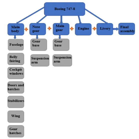
The main objective of this project is to design Boeing 747-8 Aircraft by using Solidwork Part and Surface Modelling Environment and after completion of modelling, assembling the individual parts by using Solidwork Design Environment.
PARTS MODELLED IN BOEING 747-8:
- Fuselage
- Belly Fairing
- Nose Cone
- Pitot Tubes
- Cockpit Windows
- Windshield Wipers
- Passenger Windows
- Doors & Hatches
- Lights & Antennas
- Axillary Power Unit (APU)
- Horizontal Stabilizer
- Vertical Stabilizer
- Static Discharge Tubes
- Wings
- Flaps & Ailerons
- Flap Track Fairings
- Landing Gear Axis
- Landing Gear Hatches Open
- Landing Gear Hatches Closed
- Wheel
- Nose Gear Base
- Nose Gear Suspension Arm
- Main Gear Base
- Main Gear Suspension Arm
- Engine
- Livery
ASSEMBLY MODELLED IN BOEING 747-8:
- Nose Gear Assembly
- Main Landing Gear Assembly
- Boeing 747-8 Assembly
[II] INTRODUCTION OF BOEING 747-8:
The Boeing 747-8 is a wide body airliner developed by Boeing Commercial Airplanes. It is the latest and largest variant of the 747 family. After introducing the 747-400, Boeing considered larger 747 versions as alternatives to Airbus A3XX. The stretched 747 Advanced program was launched as the 747-8 on November 14,2005, for a market forecast of 300 aircraft. The cargo version was first delivered in October 2011 and the airliner began commercial service in June 2012.
Its fuselage is stretched by 18 ft (5.6m) to 250 ft (76.3m), making it the longest airliner until the 777X-9 which first flew in 2020. On November 14, 2005, Boeing announced launching the 747 advanced as the “Boeing 747-8”. The 747-8 was intended to use the same engine and cockpit technology as that of the 787, including the General Electric GEnx turbofan and fly by wire ailerons and spoilers. Boeing states that the 747-8 is more than 10 percent lighter per seat and consumes 11 percent less fuel per passenger than the A380, translating into a trip cost reduction of 21 percent and a seat mile cost reduction of over 6 percent.
The airliner version can carry 467 passengers in a typical three class configuration over a range of 7790 nautical miles (14430 km), at the cruise speed of 0.86 mach (914km/hr).
|
Length |
76.3m |
|
Height |
19.4m |
|
Wingspan |
68.4m |
|
Maximum take- off weight (MTOW) |
4,47,696 kg |
|
Maximum Landing Weight (MLW) |
3,12,072 kg |
|
Maximum Taxi Weight (MTW) |
4,49,056 kg |
|
Power-plant |
4 x GEnx- 2B67 |
|
Engine-Model |
General Electric GEnx |
[III] DESIGN METHODOLOGY:
- Blueprint- Setup:
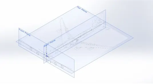
- There are three different views used in the blueprint setup (Front, Side and Top view). By using the Sketch picture option, the images are inserted and the required dimensions are given to it. By locking the feature of blueprints in the Feature-Manger Tree, we make sure that the changes are not made in the blueprints sketch by mistake.
Tools used:
- Reference geometry-Planes
2. Fuselage:
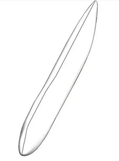
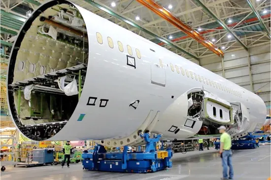
- The fuselage or body of an airplane, is a long hollow tube which holds all the pieces of airplane together. The shape of the fuselage is normally determined by the mission of the aircraft. An airliner has a wider fuselage to carry the maximum number of passengers. On an airline, the pilot sits in the cockpit at the front of the fuselage. Passengers and cargo are carried in the rear of the fuselage and the fuel is usually stored in the wings. For fighter plane, the cockpit is normally on the top of the fuselage, weapons are carried on the wings the engines and fuel are placed at the rear of the fuselage.
- Initially, required sketches of fuselage are created in the Solidwork and then by sing Surface Loft command, the half section of the fuselage is modelled. The other half is created by using Mirror command. To convert the following Surface Body to Solid Body, the Knit command is used.
Tools used:
- Surface Loft
- Mirror
- Thicken Surface
- Belly Fairing:
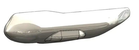
The belly fairing is a structure whose primary function is to produce a smooth outline and reduce drag. These structures are covers for gaps and spaces between parts of an aircraft to reduce form drag and interference drag. It is also called “Ventral-Fairing”.
It is located on the underside of the fuselage between the main wings. It can also cover additional cargo storage or fuel tanks and it also gives space to body landing gears.
- Belly Fairing is modelled using Boss & Extrude, Fillet, Mirror and Combine command.
Tools used:
- Combine
- Chamfer
- Fillet
- Split
- Nose Cone:
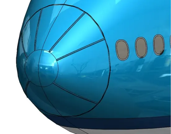
A nose cone is the conically shaped forwardmost section of a rocket, guided missile or aircraft, designed to modulate oncoming airflow behaviours and minimize aerodynamic drag. On airliners the nose cone is also a radome protecting the weather radar from aerodynamic forces. The shape of the nose cone must be chosen for minimum drag so a solid of revolution is used that gives least resistance to motion.
Tools used:
- Split
- Mirror
- Fillet
- Pitot-Tubes:
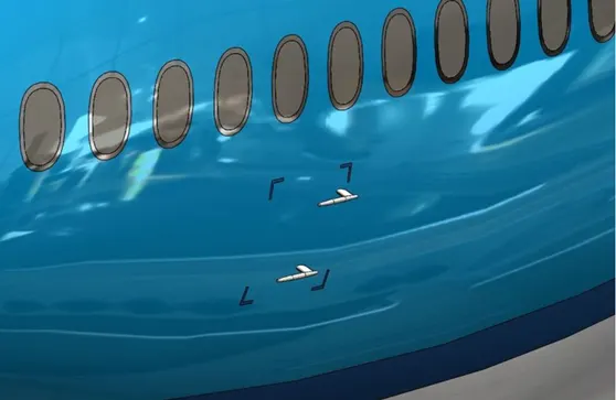
It is also known as “pitot-probes”. It is basically a flow measurement device used to measure
Fluid flow velocity. It is widely used to determine the airspeed of an aircraft. It is the
pressure sensitive instrument used to measure
- Aircraft’s airspeed
- Mach number
- Altitude
- Altitude trend
There are four pitot tubes available on the Boeing 747-8 aircraft. Two pitot tubes are on the left-hand side and other two are located on the right-hand side of the fuselage. Errors in pitot static system readings can be extremely dangerous as the information obtained from the pitot static system, such as airspeed, is potentially safety critical. It is modelled by using Extruded Boss/Base, Fillet and Revolve Command.
Tools used:
- Split
- Mirror
- Extrude Boss/Base
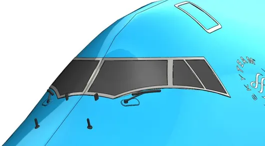
6) Cockpit Windows
A cockpit or flight deck is the area, usually near the front of an aircraft, from which the pilot controls the whole aircraft. It contains flight instruments on an instrument panel, and the controls that enable the pilot to fly the aircraft.
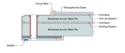
Cockpit windows may be equipped with a sun shield. Most cockpits have windows that can be opened when the aircraft is on the ground. Nearly all glass windows in large aircraft have an antireflective coating, and an internal heating element to defrost the ice if any. Ergonomics and human factors concerns are important in the design of modern cockpits.
There are two main functions of cockpit:
- To provide the pilot with a good angle of view.
- To make all control mechanisms accessible to them.
How strong is the cockpit window?
The cockpit window glass is approximately 6 centimetres thick and is reinforced with various chemicals. These glasses consist of several layers and can withstand temperatures ranging from -60 degrees to 40 degrees Celsius.
It is impossible for the glass to crack completely under normal conditions. Under extreme conditions, only first layer of the window breaks.
It is modelled by using Extruded Boss/Base, Fillet, Thicken, Offset Surface commands.
7. Windshield Wipers:
A windshield wiper is a device used to remove rain, snow, ice, washer fluid, water and debris from an aircraft’s front window. A windscreen washer system is also used to improve and expand the function of the wipers in dry or icy conditions. This system sprays water or an antifreeze window washer fluid at the windscreen using several well positioned nozzles. This system helps remove dirt or dust from the windscreen when it is used in concert with wiper blades. When antifreeze washer fluid is used, it can help the wipers remove snow or ice.
- Passenger Windows:
A typical cabin window consists of three panes:
- An outer pane flush with the outside fuselage
- An inner pane- which has a little hole used for maintaining pressurization and de-pressurization of an aircraft during ascents and descents.
- A thinner, non-structural plastic pane called a scratch pane. The aircraft cabin windows are not made of glass, but with something called ‘stretched acrylic’.
Inner panes are generally thinner at approximately 0.2’’ thick and are only present as a fail safe if the outer pane fails. The outer panes are thicker at approximately 0.4’’ thick and carry the pressure loads for the life of the window. The air gap is approximately 0.25’’ and also varies for each aircraft.
Tools used for Cockpit windows, Windshield wipers, Passengers window
- Split Line
- Mirror
- Thicken Surface
- Surface offset
- Fillet
- Shell
- Boss Extrude
- Sweep
- Move/Copy
- Block
9. Doors & Hatches:
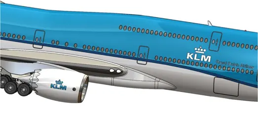
There are total of 6 doors on each side of the Boeing 747-8. The cockpit escape hatch is placed above the cockpit. In case of emergency, pilots can escape through this hatch. There are total of three hatches available on the right side of the fuselage. These hatches are available for the cargo apartment.
10.Lights & Antennas:
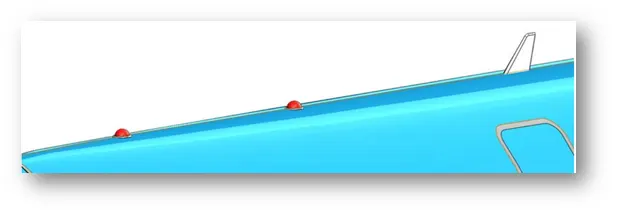
Aircraft lighting systems provide illumination for both exterior and interior use. Lights on the exterior provide illumination for such operations as landing at night, inspection of icing conditions and safety from mid air collision. Interior lighting provides illumination for instruments, cockpits, cabins and other sections occupied by crew members and passengers. Certain special lights, such as indicator and warning lights, indicate the operation status of equipment. Position, anticollision, landing and taxi lights are common examples of aircraft exterior lights.
Aircraft operating at night must be equipped with position lights. A set of position lights consists of one red, one green and one white light. The green light unit always mounted at the extreme tip of the right wing. The red light is mounted in a similar position on the left wing. The white light is usually located on the vertical stabilizer in a position where it is clearly visible through a wide angle from the rear of the aircraft.
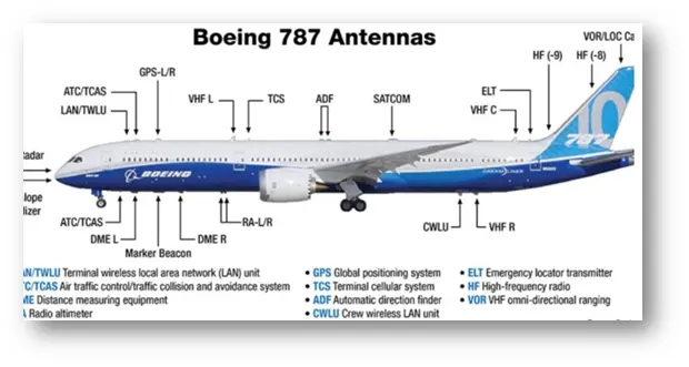
Variety of antennas are available on an aircraft. These are:
- Communication antennas
- GPS antennas
- Loran antennas
- Loop antennas
- Marker Beacon Antennas
- Navigation Antennas
- Radio Altimeters
- UHF Antennas
These units are modelled using Extruded Boss/Base, Revolved Boss/Base, Revolve, Fillet and Move commands.
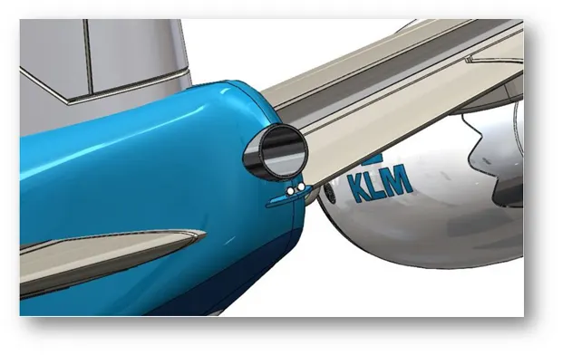
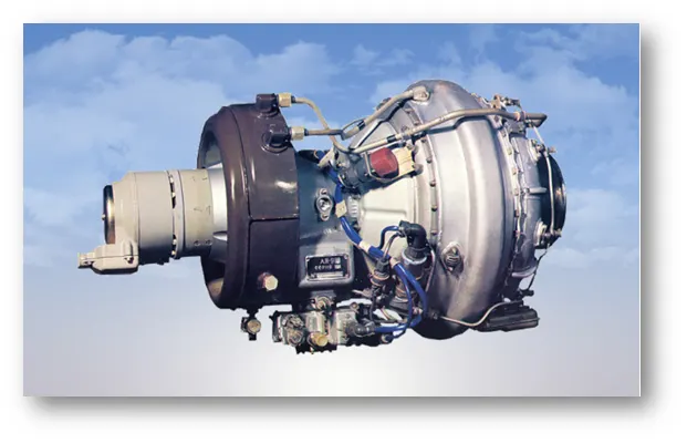
11. Auxiliary Power Unit (APU):
An Auxiliary Power Unit or APU allows an aircraft to operate autonomously without reliance on ground power unit, an external air-conditioning unit or a high-pressure air start cart.
The APU is a small jet engine which is normally located in the tail cone of the aircraft but in some cases is located in an engine nacelle or in the wheel well. The APU can be started utilizing only the aircraft battery and once running, will provide electrical power to aircraft systems as well as bleed air for air conditioning and for engine start.
It can also be used as a source of bleed air for starter assist for an inflight engine relight or to power the air-conditioning packs in the event conditions. It generally produces 115V AC voltage at 400Hz to run the electrical systems of an aircraft. It can produce power through single or three phase AC systems.
Tools used for Doors, Hatches, Lights & Antennas, APU:
- Surface Offset
- Mirror
- Split Lines
- Revolve
- Thicken Surface
- Split
- Cut/Extrude
- Dome
12. Vertical Stabilizer:
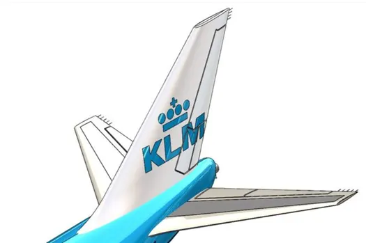
The Vertical Stabilizer is found on the tail of the aircraft. The vertical stabilizer, however is installed vertically on the airplane’s tail. It is a component that is specially designed to minimize side slip (Yaw Slip). It is also called as Rudder, which allows pilots to control the yaw moment.
There are two types of vertical stabilizers:
- Single type stabilizers
- Multi type stabilizers
Conventional Tail, T-Tail and Cruciform Tail are the types of single type stabilizers.
Twin Tail, Triple tail, Quad tail and V-Tail are the types of multi-type stabilizers.
13.Horizontal Stabilizer:
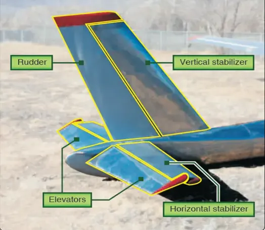
A Horizontal Stabilizer is used to maintain the aircraft in longitudinal balance, or (trim). It exerts a vertical force at a distance so the summation of pitch moments about the centre of gravity is zero.
Another role of horizontal Stabilizer is to provide longitudinal static stability. It refers to the tendency of the aircraft to return to the trimmed condition if it is disturbed. This maintains a constant aircraft attitude, with unchanging pitch angle relative to the airstream.
The elevator serves to control the pitch axis; in case of a fully movable tail, the entire assembly acts as a control surface. It also prevents up down or pitching movement. During take-off the elevators are used to bring the nose of the aircraft up to begin the climb out. During a banked turn, elevator inputs can increase the lift and cause a tighter turn. That is why elevator performance is so important for fighter aircraft.
Tools used for Vertical & Horizontal Stabilizers:
- Surface Loft
- Mirror
- Thicken Surface
- Cut Extrude
- Fillet
- Curve
- Variable Fillet
- Split Line
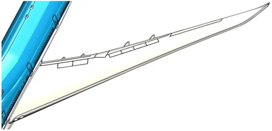
14. Wings:
Wings develop the major portion of the lift of heavier than air aircraft. The particular design of a wing depends on many factors, such as the size, weight, speed, rate of climb and use of the aircraft. The wing must be constructed so that it holds its aerodynamics shape under the extreme stresses of combat maneuvers or wing loading.
A wing’s aerodynamic efficiency is expressed as its lift to drag ratio. The lift of a wing generates at a given speed and angle of attack can be one or two orders of magnitude greater than the total drag on the wing.
For a wing to produce lift, it must be oriented at a suitable angle of attack. When this occurs, the wing deflects the airflow downwards as it passes the wing. Since the wing exerts a force on the air to change its direction, the air must also exert an equal and opposite force on the wing, resulting in different air pressures over the surface of the wing.
 15. Flaps & Ailerons:
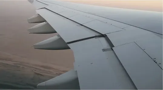
Flaps are mounted on the trailing edge on the inboard section of each wing (near the wing roots). They are deflected downward to increase the effective curvature of the wing. Flaps raise the maximum lift coefficient of the aircraft and therefore reduces the stalling speed. They are used during low speed, high angle of attack flight including take-off and descent for landing. Some aircraft are equipped with “flaperons”, which are commonly called “inboard ailerons”.
The ailerons control the rolling movement along the lateral axis of an aircraft. Whenever lift is increased, induced drag is also increased. When the stick is moved left to roll the aircraft to the left, the right aileron is lowered which increases lift on the right wing and therefore increases induced drag on the right wing. Differential ailerons are ailerons which have been rigged such that the down going aileron deflects less than the upward-moving one, reducing adverse yaw.
16. Flap Track Fairings:
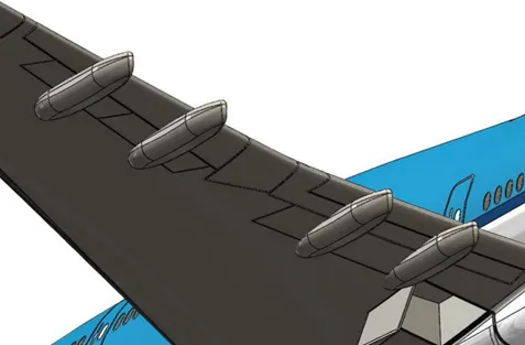
A flap track fairing is a secondary structure whose function is to provide an aerodynamic cover and so reduce drag. Flaps are used to reduce take-off and landing distance. It is mounted under the trailing edge of the fixed wing aircraft. Boeing 747-8 has total 8 flap track fairings, 4 on the left and 4 on the right.
Tools used:
- Surface Loft
- Variable Fillet
- Surface Offset
- Body Delete/Keep
- Split Line
- Surface-Offset
- Combine
- Mirror
17. Landing Gear Hatches Closed and Open:
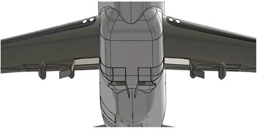
To decrease drag in flight, undercarriages retract into the wings and fuselage with wheels flush with the surrounding surface or concealed behind flush mounted doors. The doors are hinged back-to-back in the center of a Boeing 747-8 fuselage and open only when the landing gear are retracted or deployed. The landing gear hatches are operated electrically and hydraulically.
Doors remain closed and locked in the event of inadvertent landing gear deployment (during malfunction of landing gear deployment).
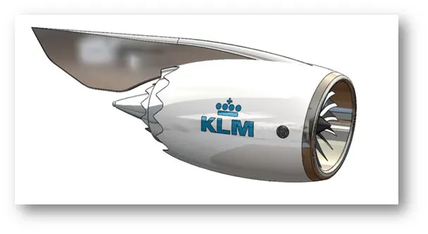
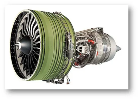
18. Engine:
An aircraft engine, often referred to as an aero engine, is the power component of an aircraft propulsion system. Most aircraft engines are either piston engines or gas turbines (air- breathing engines). In commercial aviation the major western manufacturers of turbofan engines are Pratt & Whitney, General Electric, Roll-Royce and CFM International.
In general, aircraft engines are internal combustion engines. Most modern subsonic jet aircraft use more complex high bypass turbofan engines. They give higher speed and greater fuel efficiency than piston and propeller aeroengines over long distances.
Turbofans are the dominant engine type for medium and long-range airliners. Turbofans are usually more efficient than turbojets at subsonic speeds, but at high speeds their large frontal area generates more drag.
The engine used for the Boeing 747-8 is General Electric GEnx-2B67 next generation engine. The design of the 747-8 aircraft engine is slightly modified variant of the GEnx engine developed for the Boeing 787 Dreamliner aircraft. The engine provides 65,500 lb of thrust (296 KN).
Tools used for Engine:
- Surface Loft
- Variable Fillet
- Surface Offset
- Body Delete/Keep
- Split Line
- Surface-Offset
- Combine
- Mirror
- Surface Revolve
- Revolve Thin
- Draft
- Surface Trim
- Shell
- Cut Extrude
19. Livery
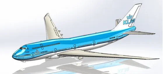
The aircraft liveries and logos of airlines are used to provide distinctive branding for corporate and commercial reasons. Often, they also combine symbols of national identity while being acceptable to an international market.
BOEING 747-8 ASSEMBLY:
In this modelling, first the initial models were created and then the assembly was done. This type of approach is called as Bottom-up Approach. Then the parts were assembled using various mate options in the Solidwork Assembly Environment.
- Nose Gear Assembly:
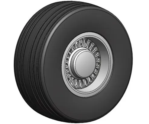
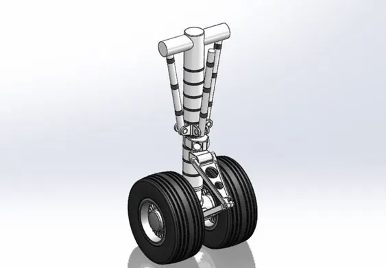
Nose Gear Base, Wheel and Nose Gear Suspension Arm are the parts used for Nose Gear sub part. Then all the models were created individually and then the assembly was done followed by the sub-assembly parts in the Solidwork assembly Environment. In Boeing 747-8 it has only one nose landing gear.
- Main Landing Gear Assembly:
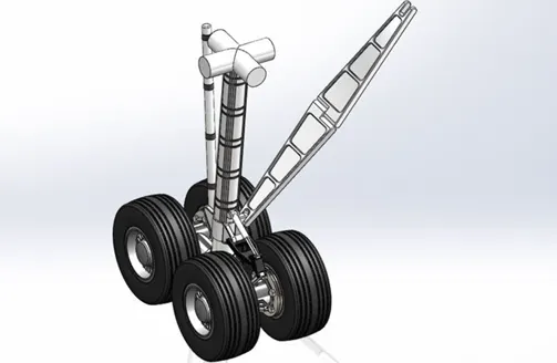
It consists of main gear base, two main gear suspension arms and four wheels. This is also modelled and assembled by similar approach as done for the Nose Gear Assembly. Boeing 747-8 has 4 main landing gear. Two are wing landing gears (Assembled under the wing of an aircraft) and 2 are body landing gears (Assembled under the fuselage of an aircraft). After the completion of all the model creation and sub-assemblies of an aircraft, final assembly of Boeing 747-8 was done in the Solidwork Assembly Environment.
First the livery part of the main body (fuselage with all the associated parts) is inserted into the assembly section and made fixed. Then the engine was inserted for the assembly. The engine was assembled using the engine right plane, front plane and top plane with the main livery part specific planes for the successful application of mates which we had given (Coincident, Concentric and Distance mates).
Same steps were followed by the nose and main landing gears.
There are different types of mates used in the project:
- Coincident mates
- Distance mates
- Concentric mates
- Angular mates
- Gear mates
Gear mates plays an important role in the movement of the mechanical components modelled in Solidwork. This mate is applied to nose and main landing gear so that it moves appropriately in the desired location.
[IV] SKETCH TOOL & FEATURES USED FOR MODELLING:
SKETCH TOOL USED
The Sketch Fillet tool trims away the corner at the intersection of two sketch entities to create a tangent arc. This tool is available for both 2D and 3D sketches. The Fillet tool on the Features toolbar fillets entities such as edges in parts.
The Sketch Chamfer tool applies a chamfer to adjacent sketch entities in 2D and 3D sketches. This tool is available for both 2D and 3D sketches. The Chamfer tool on the Features toolbar chamfers entities such as edges in parts.
Offset one or more sketch entities, selected model edges, or model faces by a specified distance. For example, you can offset sketch entities such as splines or arcs, sets of model edges, loops, and so on.
You can create one or more curves in a sketch by projecting an edge, loop, face, curve, or external sketch contour, set of edges, or set of sketch curves onto the sketch plane.
You can use intersection curves to measure the thickness of a cross section of a part.
You can extract iso-parametric (UV) curves from a face or surface. Applications of this functionality include extracting the curves for imported surfaces and then performing localized cleanup using the face curves.
Select the trim type based on the entities you want to trim or extend. All trim types are available with 2D sketches and 2D sketches on 3D planes.
You can add to the length of a sketch entity (line, centerline, or arc). Use Extend Entities to extend a sketch entity to meet another sketch entity.
You can split a sketch entity to create two sketch entities. Conversely, you can delete a split point to combine two sketch entities into a single sketch entity. Use two split points to split a circle, full ellipse, or a closed spline.
You can jog sketch lines in 2D or 3D sketches in part, assembly, and drawing documents. Jog lines are automatically constrained to be parallel or perpendicular to the original sketch line.
Use the Make Path tool to create machine design layout sketches. For example, you can model cam profiles where the tangent relation between the cam and a follower automatically transitions as the cam rotates. A path enables you to create a tangent relation between a chain of sketch entities and another sketch entity.
You can convert sketch entities in a sketch or drawing to construction geometry. Construction geometry is used only to assist in creating the sketch entities and geometry that are ultimately incorporated into the part. Construction geometry is ignored when the sketch is used to create a feature. Construction geometry uses the same line style as center lines.
Select Mirror Entities to mirror pre-existing 2D sketch entities on a plane, and then select the entity about which to mirror. If you want to first select the entity about which to mirror, and then sketch the entities to mirror, select Dynamic Mirror Entities
FEATURES USED
Loft creates a feature by making transitions between profiles. A loft can be a base, boss, cut, or surface.
Pattern repeats the selected features in an array based on a seed feature. You can create a linear pattern, a circular pattern, a curve driven pattern, a fill pattern, or use sketch points or table coordinates to create the pattern.
Revolves add or remove material by revolving one or more profiles around a centerline. You can create revolved boss/bases, revolved cuts, or revolved surfaces. The revolve feature can be a solid, a thin feature, or a surface.
You can scale a part or surface model about its centroid, the model origin, or a coordinate system.
The shell tool hollows out a part, leaves open the faces you select, and creates thin-walled features on the remaining faces.
Surfaces are a type of geometry that can be used to create solid features. Surface tools are available on the Surfaces toolbar.
Sweep creates a base, boss, cut, or surface by moving a profile (section) along a path. A sweep can be simple or complex.
Creates a solid feature by thickening one or more adjacent surfaces.
[V] RENDERING:
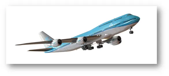
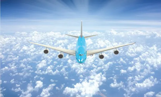
Rendering or image synthesis is the process of generating a photorealistic or non-photorealistic image from a 2D or 3D model by means of a computer program. The resulting image is referred to as the render.
It can be done in 2 ways in Solidwork. These are:
- Photo view 360
- Solidwork Visualize
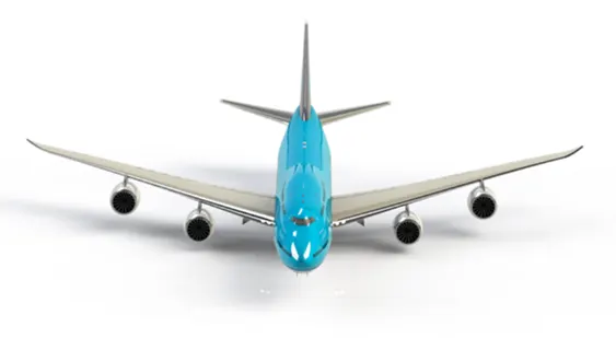
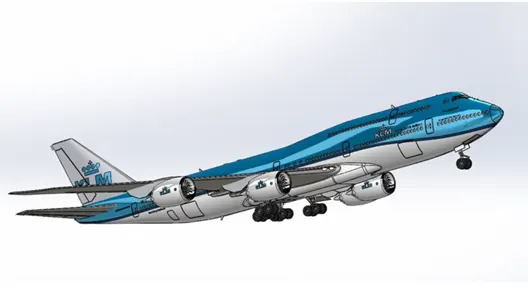
Some of the rendered BOEING 747-8 Final Assembly images are given below:
[VI]CONCLUSION:
In this project, various models/parts were created using many commands and area like Surface, Solid modelling and combining all the models by using assembly feature available in Solidwork. Rendering was done to come out with realistic effect on the assembly that we have modelled using Photo view 360 and Solidwork Visualize.