Bird Strike - Project - 2
BIRD STRIKE IN AERO ENGINE
Objective
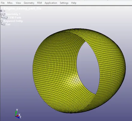
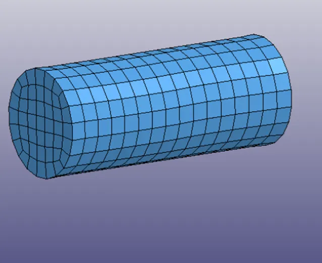
Part: Engine casing
- Engine casing is the stationary part here should not move from its location. The keyword for parts node and it's node set are single file. The material card for the same and it's boundary conditions also having each. Kfile and it is directly include in the main. K file.
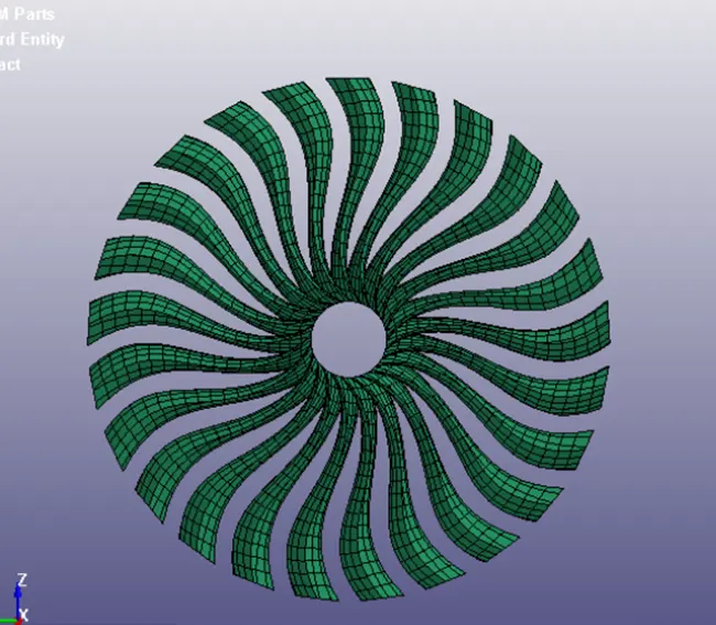
Part:Blade
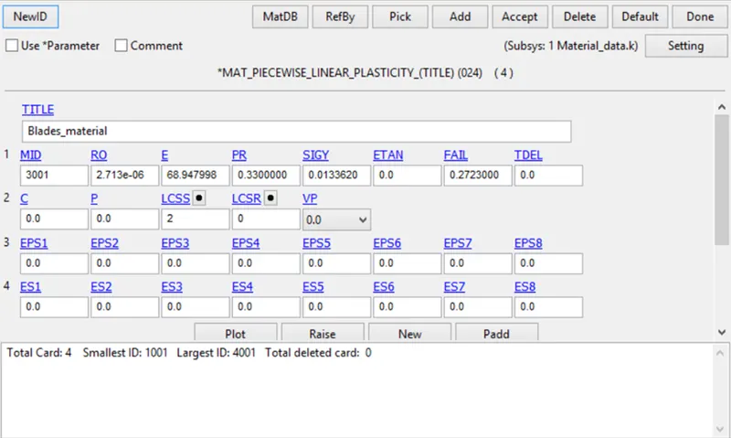
- In this project blades are the main component it should rotate with some angular velocity 0.5 mm/ms and material properties are slightly lower than bird so as to break earlier when the bird is making contact with it. The contact keyword is added to the blades part file. This will allow blade not to penetrate with adjacent blades. This is done by trial and error method.
Part: Hub
- The hub is the solid component and it is meshed with tras the hub is connected with blades so that the contact between blade and hub is not required. The hub is then roate, if blades will rotate with respect to particular axis.
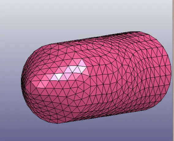
Part: bird
- Bird is the shell component which is provided with 20mm/ms velocity and it hits the blades.
Material
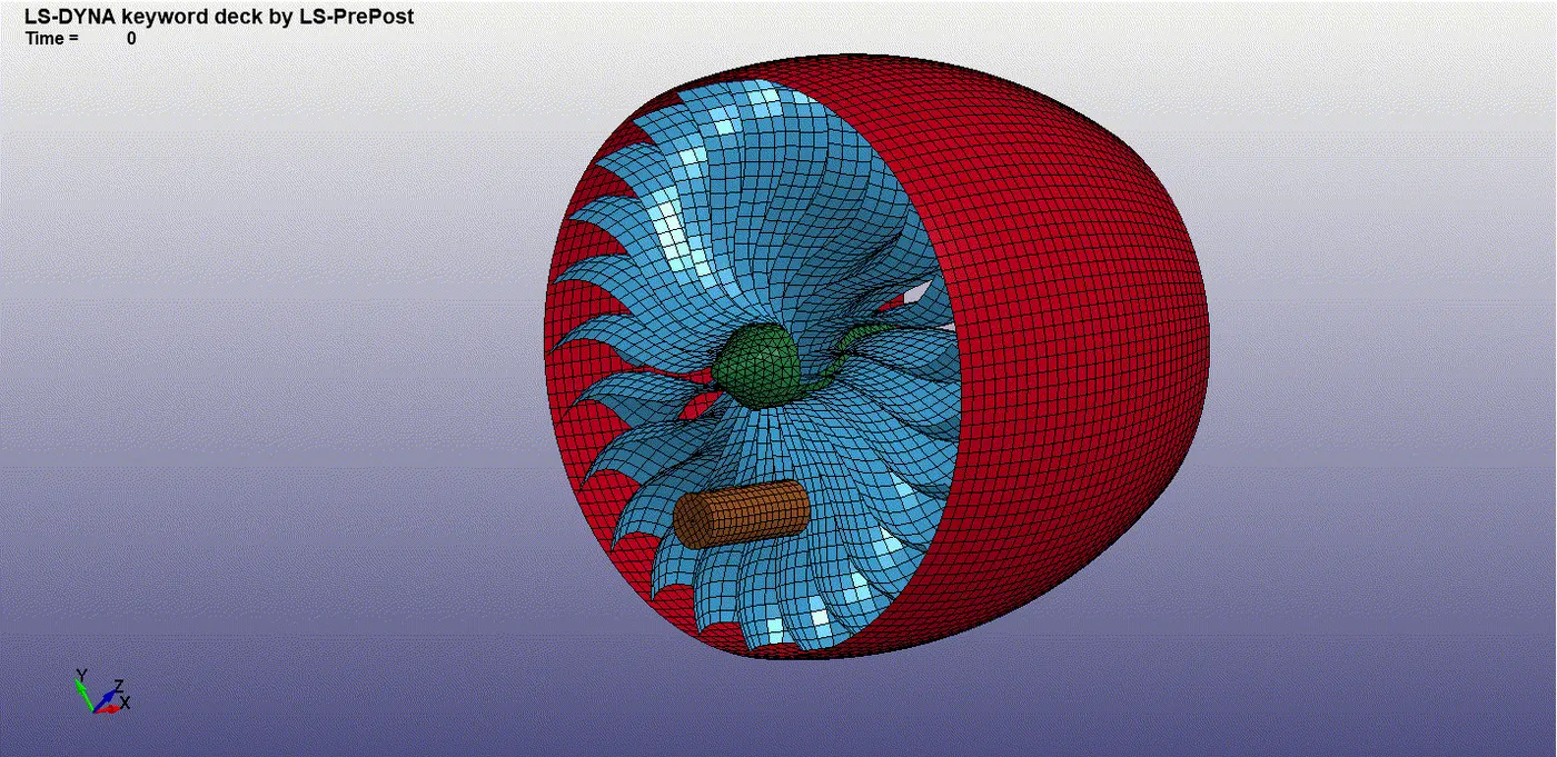
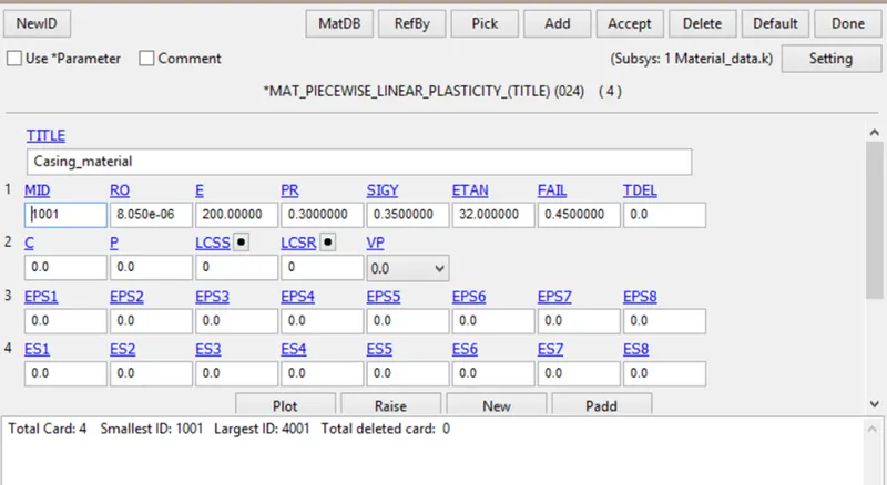
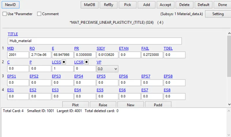
- The part of the bird strike model setup are modelled with different materials to create the expected scenario. Blades are connected to the central hud thus forming a rotating sub structure.
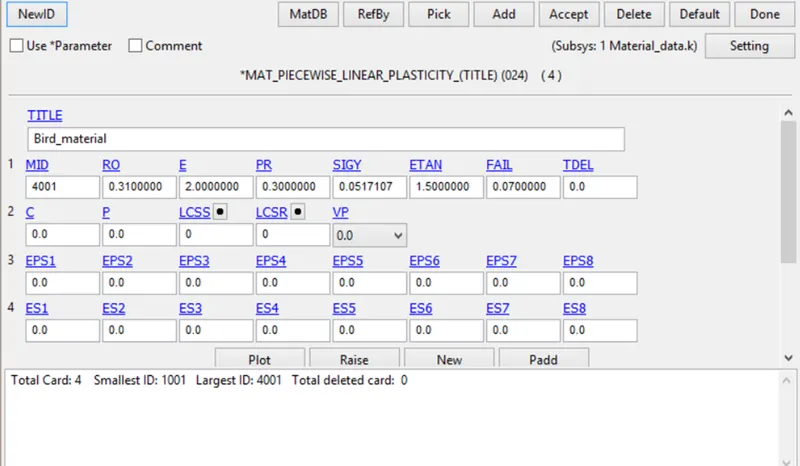
- The hub is a thick component when compared to the fan blades and is not likely to experience damage or failure because the fan blades will fail before damaging loads were transferred to the hub stresses are not determined and it was assigned with rigid steel material properties.
- The engine casing and hub are modeled with rigid material as they do not account for any deformation in the model during the event.
Section creation
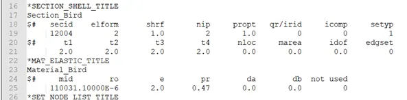
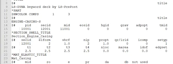
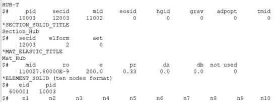
- It can be seen that the bird blades and engine casing are made up of shell elements but the hub is made up of solid elements.
- Using *Section_shell card all the parts except the hub are modeled with shell element formulation.
- Similarly the hub is modeled with *section_soild card with tetra-hedron element formulation.
4. Boundary conditions
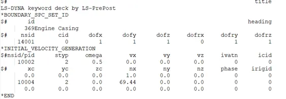
- The conditions that are given here require the bird to go towards the aero engine. The velocity of the bird was 600 km /200 mm/ms.this was done by assigning the node-set created for the bird in the boundary_prescribed_motion card.
- The blade and the hub were given a rotatonal velocity of 2.with higher rotational velocities the simulation tended to be a bit unstable with the blades getting detached and flying outwards.
- This was done using *initial_velocity_generation card.
contact modeling
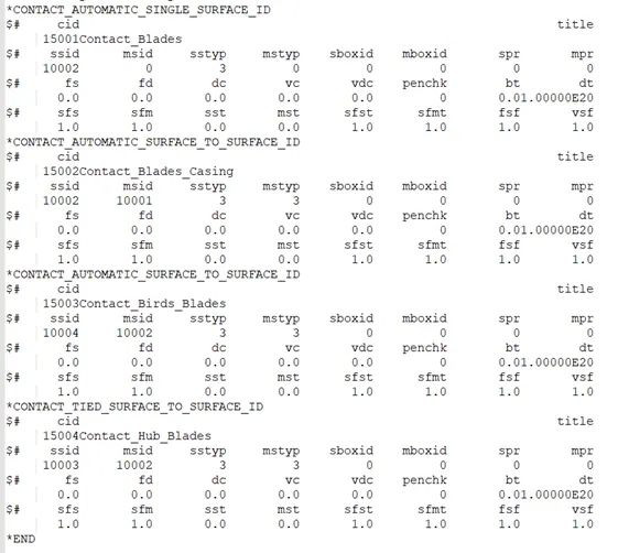
- Contact are defined between different parts to avoid penetration during impact scenario
- In case of bird impacting the fan blades directly it is important to assign the proper contact between
5. Control card
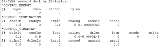
- The termination time for this simulation is given to be 10 ms. Apart from *Control_TErmination, *Control_Hourglass is used to interpret hourglass energy.
- To track initial penetration during contact *control_energy has been used * control_timestep card is also utilized in the simulation.
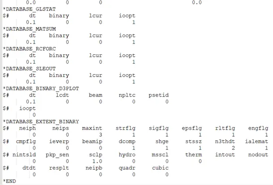
6.database Ascii and database_extent_binary cards are used to get output file. Glstat, Matsum, Sleout, Rwforce are written.
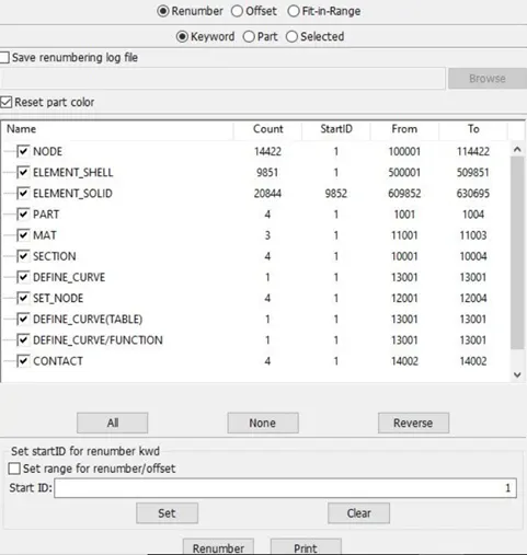
7. Renumbering.
- the renumbering is done as perthe problem statement
von-mises contour
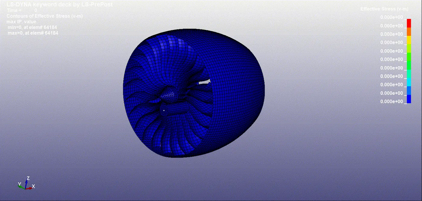
- there is initial stress between the blades and the hub.this is due to to the contact definition.as soon as the bird the blade there is a spike in the effective stress value
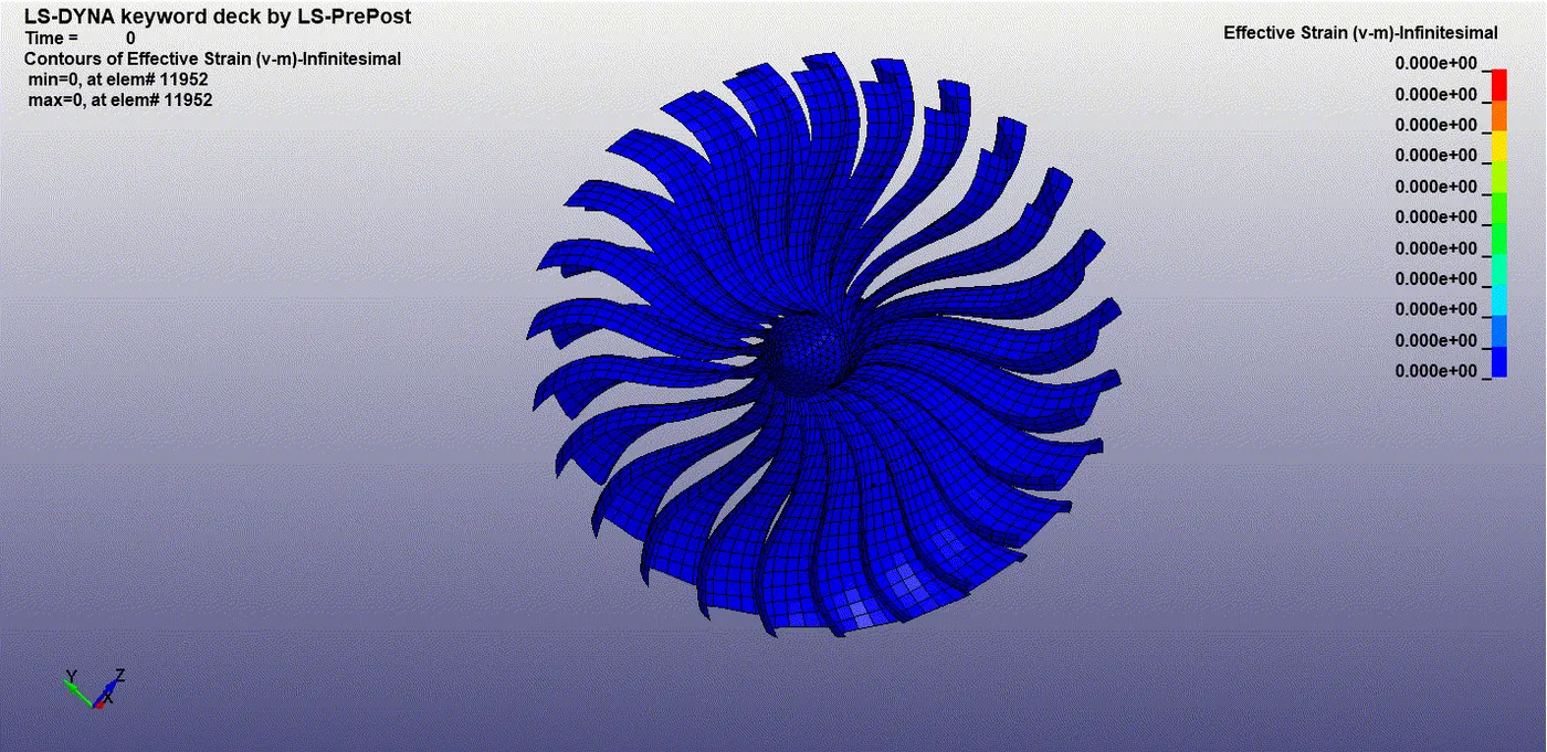
- the bird strike the strain is generated on the blade which is slowly transffered to the rest of the blades . maximum strain obtained is 0.983.
- note: there is might be a change in the value of stress and strain in the case of the simulation without mass scaling.this is because the addedmass might change the values.however a huuge difference in value wont be observed.
Energy plots.
The globel energy plot is shown below
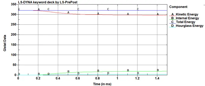
- as shown in the above figure after the bird strikes the kinetic energy decreases which causes an increase in the internal energy of the system .the hourglass energy remains close to zero during the entire simulation.
Effective plastic strain
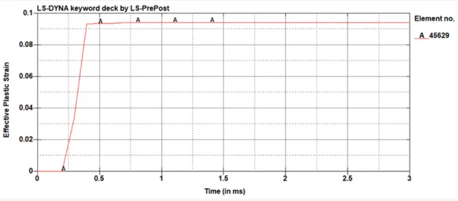
the element corresponds to the element near the deformation region.the plastic strain increases as the bird strike the blade and after which it remains constant.
Conclusion:
all the objectives given in the problem statement are satisfied.from this challange the following concepts are learnt.
- renumbering in accordance with the standards.
- usage of include keyword/
- mass scaling and its significance without compromising the stability of the model is learnt.
- running the simulation and debugging the error.
G Link
https://drive.google.com/file/d/11GfYk_P28r_UoDrNhsqPHkYCPCs2Mjno/view?usp=sharing