Bird Strike - Project - 2
LS-DYNA Course (Structural Mechanics / FEA)
Week 12 Challenge :-
Objective :-
The main objective of this project is to use all the combined knowledge derived from LS-DYNA towards simulating the most common crash dynamics of an airplane engine. As far as airplane engine R&D is concerned, a bird strike is one of the durability tests which the engine has to go through virtually and physically. But since physical testing costs are high and it can only be performed once at the end, the virtual testing takes precedence. With the help more detail oriented computational software, a real-world situation can be easily simulated and normally goes hand in hand with the physical test.
Bird strikes usually occur close to the lower atmosphere i.e., during take-off or landing. Although steps are taken to avoid such a condition but preparation for the strike has to be well organized. Nowadays engines are much sturdier with high material durability such that it can survive a bird strike. In this simulation, we are given the basic model of an airplane engine along with a basic bird model. We have to input all the necessary conditions which will help us simulate this project. We are also given the engine blades material for input. We try to run this complete simulation is run as per companywide practices, as much as we can.
Case Setup Steps and User defined Parameters:-
For this project, we employ the approach taken by almost all manufacturers. As we mentioned that we are following company practices, this means that there will be one main file with its separate sub-files. This main file will only contain reference codes to extract data from the other sub-files. No other input shall be given to the main file. This also prevents confusion of data between each sub-file.
As mentioned in the start of the project, this nonlinear transient dynamic problem will be solved using the Explicit solver.
The unit system to be used for this project is - Kilograms, Millimeters, Milliseconds. We make sure each sub-file has the same unit system employed, to avoid any numerical errors.
Trying to simulate this problem with real-world parameters. We look into the velocities and other conditions.
- Airplane engines at max thrust rotate at 20,000 RPM. Converting that to our unit system gives us 2 rad/ms or 4590 mm/ms of rotational velocity.
- A bird has the travel velocity of 60 mph. Converting to our unit system we get 27 mm/ms.
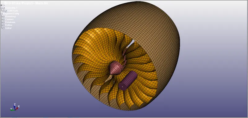
Image 1 – Complete Model for Airplane Engine and Bird
The above image is the complete set up of the bird and the airplane engine which is to be simulated and the results observed.
We go on to define the material properties of each individual component of this simulation.
For Airplane Engine Hub/Cone -
This material is free to be user defined, so we use a Nickel-Iron alloy. Below are the material properties (In the Kg, mm, ms system):-
Density = 8200 Kg/m3 = 8.2 x 10⁻⁶ (Input)
Young’s Modulus = 145 GPa = 145 (Input)
Poisson’s Ratio = 0.3 = 0.3 (Input)
Yield Strength = 810 MPa = 0.81 (Input)
Tangent Modulus = 58 GPa = 58 (Input)
For Airplane Engine Blades -
The material for the Blades is provided. This material is defined to be an Aluminum alloy AL-4495. We do not need to input anything else since the material model contains all necessary parameters. We simply call the material model into the Main .K file.
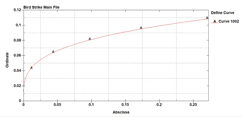
Image 2 – Curve followed for Blade Material
For Airplane Engine Casing -
We are given a reference material for the Airplane engine casing to be 200 GPa. From the options available and as per user discretion, we choose A36 Steel to be the material for our Casing. The material properties are as follows (In the Kg, mm, ms system):-
Density = 7800 Kg/m3 = 7.8 x 10⁻⁶ (Input)
Young’s Modulus = 200 GPa = 200 (Input)
Poisson’s Ratio = 0.32 = 0.32 (Input)
Yield Strength = 250 MPa = 0.25 (Input)
Tangent Modulus = 78 GPa = 78 (Input)
For Bird -
We are given to choose an Elastic material for the bird model, which has 2000 MPa (2 GPa). Thus, we select the appropriate properties from the internet and list the material properties below (In the Kg, mm, ms system):-
Density = 2 g/cm3 = 2 x 10⁻⁶ (Input)
Young’s Modulus = 2 GPa = 2 (Input)
Poisson’s Ratio = 0.15 = 0.15 (Input)
Node Numbering Reference :-
In such projects, node/element/part numbering plays an important role to identify each member accurately. This number system also helps us identify the location of the errors, if that be the case. All companies with crash testing labs have their own unique node numbering system.
However, for this project we stick with the node numbering system as provided from the model. Our node numbering is as follows:-
Node Numbers – 372 to 44007
Element Numbers – Shell = 5547 to 64993 ; Solid = 1 to 63143
Part Numbers – 1001 to 1004
Other Keyword numbers – 10001 to 10104
Execution of Steps :-
The MAIN file will only consist of primarily DEFINE and INCLUDE keywords as mentioned. Apart from those cards we will have to initiate a KEYWORD_ID and TITLE card for this main file as well. Every other parametric card will be input in separate .K files and the MAIN file will access these parameters via DEFINE_TRANSFORMATION along with INCLUDE_TRANSFORM.
- We define the KEYWORD_ID and TITLE input cards only for the MAIN .K
- The ELEMENT and NODE cards for this project get initiated after all the sub-files have been called into the MAIN .K
We move on to create all the .K sub-files in their respective orders and number them for the sake of organization.
- We are provided the airplane and bird models in one single file, but for the sake of ease we separate each model into its individual files. File number 1 to 4 are ; 1) Airplane Casing model ; 2) Bird model ; 3) Blades model ; 4) Hub/Center cone model.
- The next file is the MAT cards for our simulation. The material for the Casing, bird and hub are included in this file number 5. The material model for the blades is already given so we do not need to create its material card.
The material properties for each part are mentioned in the case setup. We use MAT_PIECEWISE_LINEAR_PLASTICITY (MAT_024) for the Casing and the Hub. MAT_ELASTIC (MAT_001) is used for the bird material.
Since the MAT model for the Blades is in a separate .K file, we call the file into the main file under number 7.
- The SECTION card is input under file number 6. Shell elements are used for the Casing, Bird, and the Blades, whereas the Hub is formed from a Solid. We create this .K sub-file with the following user defined inputs:-
Casing (SECTION_SHELL) -> ELFORM = 2; Thickness = 5 mm
Bird (SECTION_SHELL) -> ELFORM = 2; Thickness = 6 mm
Blades (SECTION_SHELL) -> ELFORM = 2; Thickness = 3 mm
Hub (SECTION_SOLID) -> ELFORM = 10 (For Tetrahedron)
- File number 8 is used to create the DATABASE These cards will help us gather all the output parameters associated with our simulation. We choose the following cards:-
In DATABASE_ASCII Option : GLSTAT, MATSUM, SLEOUT, NODOUT, RCFORC and DATABASE_BINARY_D3PLOT.
All of the above will have the Time Interval (DT) = 1 ms.
We introduce the DATABASE_EXTENT_BINARY card, in which we enter STRFLG = 1. The STRFLG will help us calculate the Strain values in this simulation.
In the DATABASE_HISTORY_NODE, we select a few nodes on each blade of the airplane engine to get the required output values.
- The CONTROL cards are defined as File number 9. Termination time comes under the keyword, CONTROL_TERMINATION and will have Termination time = 100 milliseconds (Since initially this might be a complex simulation taking time).
CONTROL_ENERGY (HGEN = 2, RWEN = 2) and CONTROL_HOURGLASS (IHQ = 1) cards are entered as well.
- File number 10 is input for the curves needed for the motion in the blades and the bird. This comes under the keyword DEFINE and the curves are as follows :-
Curve 1 (LCID 20000) - For the blades we input velocity to the Hub, 2 mm/ms is entered for this curve. This velocity will be constant throughout the time of this project.
Curve 2 (LCID 20001) - For the bird, we enter 27 mm/ms; where the bird goes from 0-27 in the first 20 ms and then stays at 27 mm/ms.
- All the Node sets are entered for their respective function under SET card, which is File number 11.
NSID – 10100 is input for keeping the Airplane Engine Casing stable. We select 4 nodes around the Casing.
NSID – 10101 is used for the bird, in order to enter the motion parameter.
NSID – 10102 is used to define the nodes responsible for making the hub and blades rotate.
- The above Node sets are given their respective parameters under the BOUNDARY input card. File number 12.
- Firstly, we initiate BOUNDARY_SPC_SET for the Casing and use its NSID 10100 to restrain all the degrees of freedom for the Casing. This is done so that the Casing stays in place does not see residual motion.
- Next, we input the rotational velocity for the Blades by using the Hub NSID – 10102. For this BOUNDARY_PRESCRIBED_MOTION_SET card is used and LCID 20000 is used to give a +ve X-direction rotational velocity.
- Lastly, we enter the BOUNDARY_PRESCRIBED_MOTION_SET card for the bird model. NSID 10101 and LCID 20001 is used to give a +ve X-direction translational motion to this bird.
- Now we have to enter the CONTACT between each member under File number 13.
- To avoid self-contact and error during the simulation, CONTACT_AUTOMATIC_SINGLE_SURFACE card is for the Bird and the Blades. We need to only enter the SLAVE ID, where we enter the PART ID for each in separate cards.
- CONTACT_AUTOMATIC_GENERAL is used to define the contact between:-
Bird to Blades, Bird to Casing, Blades to Casing (PART ID for each member are used in this card).
For the first contact card, Bird is the Slave part and Blade is the Master.
For the second, Bird is the Slave part and Casing is the Master.
Lastly, Casing is the Master (Since it cannot move) and Blade is the Slave part.
- The last file number 14 is for the PART We note down all the MAT and SECTION identity numbers for the easy of entry. This file will contain the MID and SECID correctly entered for all the parts in order to tie the whole MAIN file together and connect respective cards.
Now that we have all the files initiated and ready to use. Each file, respective of its number, is input in the MAIN .K file using the cards DEFINE_TRANSFORMATION and INCLUDE_TRANSFORM.
After checking the MAIN file, in LS-PrePost, to see that all the cards show up correctly; we run the simulation for this MAIN file and observe the results.
Trial and Error plus Debugging :-
We encounter certain errors to fix the simulation, in order to make it run smooth. Below listed is the flow of the errors we caught/experienced and the solution we employed to correct them.
Trial 1 (Error Termination)
Error – We get a minor warning where the processor deletes duplicate nodes that may have been created along the way. (This warning is not critical, and the program can run)
Two main errors are displayed where the DEFINE_TRANSFORMATION ID is not properly entered and fails to process further.
Fix - We re-write the MAIN file to fix these errors and check for anymore transformation errors.
Trial 2 (Error Termination)
Error – DEFINE_TRANSFORMATION ID 14 (PART) keeps getting removed from the processing scripts and stops the program.
Fix – Instead of importing a sub-file with the PART keyword parameters. We connect the MID and SECID for the PART card, in the MAIN file itself. We also remove the File number 14 from the DEFINE and INCLUDE cards in the MAIN file.
Trial 3 (Error Termination)
Error – Some error causing the removal of the DEFINE_TRANSFORMATION kept occurring. This stopped the program since the missing Transformation card threw an error.
Fix – Tried to fix the error in Notepad++ to avoid any parameters from being removed.
Trial 4 (Normal Termination)
This file took 2 hrs and 43 mins to run. On starting the simulation, we observed that the bird failed to contact/interact the blades and went through them. The rotational velocity given to the hub fails to execute. Hub and blades are stationary.
Fix – We adjust the Master and Slave parts in the CONTACT_AUTOMATIC_GENERAL cards. Also, for sake of managing time, we reduce the TERMINATION TIME from 100 ms to 20 ms.
We try to solve the bird contact problem before we solve the rotational velocity problem.
Trial 5 (Normal Termination)
This file took 27 mins to process. On observing the simulation, the bird still goes through the blades with any interaction. The rotational velocity given to the hub + blades fail to execute again.
Fix – This time we change the CONTACT cards from CONTACT_AUTOMATIC_GENERAL to CONTACT_AUTOMATIC_SURFACE_TO_SURFACE, using the originally entered parameters.
We also change the translational bird velocity to 5 mm/ms from 27 mm/ms (LCID 20001) in the DEFINE_CURVE file.
We reduce the Hub Rotational velocity from 2 mm/ms to 1 mm/ms (LCID 20000) in the DEFINE_CURVE file.
We also try to change the Rotational degree of freedom in the BOUNDARY_PRESCRIBED_MOTION_SET for the Hub to check.
Trial 6 (Normal Termination)
The bird finally interacts with the blades but causes the blade+hub setup to move backwards. The blades still show no rotational motion.
Fix – We switch the motion parameter for the blade+hub from BOUNDARY_PRESCRIBED_MOTION_SET to INITIAL_VELOCITY_GENERATION.
To prevent any unnecessary motion to the hub setup, we impose BOUNDARY_SPC_SET to the hub of the engine.
NSID – 10103 is the node set include one node in front of the hub and one node at the back of the hub to which a restrained will be input via BOUNDARY_SPC_SET.
NSID – 10104 is a Part set which includes the Blade (Part number 1003) and Hub (Part number 1004) for the rotational velocity to be imposed via to INITIAL_VELOCITY_GENERATION.
We also make the bird translational velocity parameter from BOUNDARY_PRESCRIBED_MOTION_SET to INITIAL_VELOCITY_GENERATION.
The BOUNDARY sub-file number 12 now only has SPC_SET in the parameters. We also remove the DEFINE sub-file number 10 since we do not need the curves for the INITIAL cards.
Trial 7 (Normal Termination)
This file is a success. It takes a total time of 1 hr 10 mins to execute the program. The blades are rotating, the bird interacts with the blades without moving the setup, the blades and casing do not penetrate one another. This is a successful simulation.
However, we run one last simulation with a few refined input parameters.
Bird Translational Velocity is changed from 5 mm/ms to 2 mm/ms in the INITIAL card.
Hub+Blade Rotational Velocity is changed from 1 mm/ms to 0.5 mm/ms in the INITIAL card.
The TERMINATION TIME in the CONTROL card is changed from 20 ms to 30 ms.
This is our final simulation, and we consider this file for our final results and plot.
Results and Graphs :-
The results from this simulation give us general idea of how a bird interacts with an airplane engine. In the real-world, the bird does not stand a chance but since we do not have real-world conditions in place, we analyze the results of this simulation.
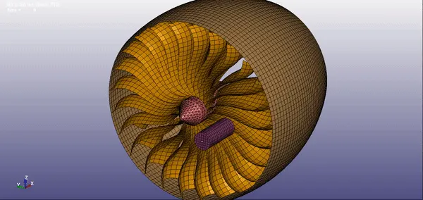
Image 3 – Bird Strike Simulation Gif
As per the simulation, the bird contacts the blades, and we observe the bird comes off the blades with experiencing forces.
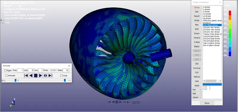
Image 4 – Bird Strike Simulation Final Timestep
This above image is the final time interval of this simulation, in which we see the bird come off of the blades and maintain its integrity. In actuality the bird would lose its complete integrity and fail versus an airplane engine.
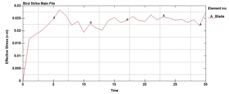
Graph 1 – Stress experience by the blade
The above graph shows us the effective stress experienced by the blades. Since the material is sturdier, it sees a peak at contact interval with the bird. But general stress levels are low due to the material properties of the blades.

Graph 2 – Stress experience by the bird
In case of the bird, it experiences higher stress values due to its material properties being weaker than the blades. The peak of the stress plot is when the bird contacts the blades. Since we lack details on the bird losing integrity, it simply comes off the blades.
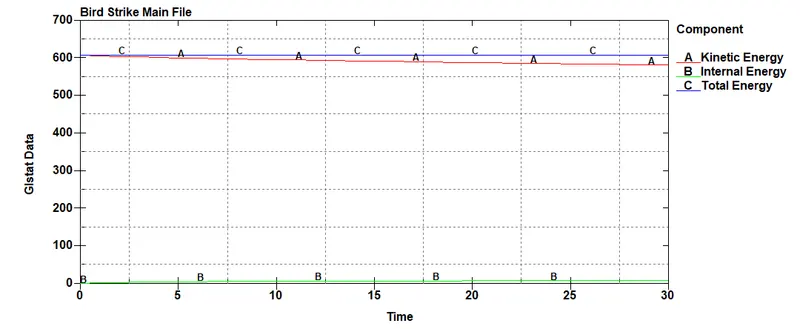
Graph 3 – Energy plot for the complete simulation
This final plot denotes the energies experience by the complete simulation. Total Energy, as it should, remains constant whereas kinetic energy has a slight decline.
We also observe that real world conditions need more refining and detailing in order to run, so we ended up running this file as per user defined parameters. This concludes our results and plots analysis, and we move on towards our conclusion.
Conclusion:-
We conclude this simulation by successfully performing a close-to company level simulation. Since we did not include the bird as SPH, we could not go into much detail for this simulation. These details were not added to the model to reduce complexity, but the generic elements included, we completed this bird strike analysis. The results and graphs show us the overall picture of how a bird will interact when striking an airplane engine.
Even though the details make a model precise and accurate, for the sake of our project we just needed a general idea of this simulation. This area of research is very widespread because majority of the bird strikes have a negative impact on the engine and plane functions. But as technology advances, we can effectively match real-world crash conditions in any software simulation.