Bird Strike - Project - 2
TITLE: BIRD STRIKE IN AERO ENGINE
Bird-strike events are relatively common, occur most often on the ground or at low altitude. However, bird strikes can have significant economic and occasional safety consequences for flight operations. Pilots and operators should be knowledgeable about the hazard, and flight crews should use facts, data, and standard operating procedures to reduce the potential for and consequences of a bird strike.
While bird strikes usually inflict most damage on the engines, all areas of an airplane can be damaged.Airplane damage and effect on flight from bird strikes are closely correlated to kinetic energy, derived from the mass (determined by bird species) and the square of the speed of the collision. (A 20 percent increase in speed raises the kinetic energy by 44 percent.)
Single or multiple large birds, relatively small numbers of medium-size birds, and large flocks of relatively small birds are all problematic and have resulted in accidents. In the United States, a list of birds most hazardous to flight has been identified: large flocking waterfowl (Canada goose); gulls; pigeons and doves; blackbirds, starlings, and sparrows; and raptors (hawks and kestrels). Most bird strikes occur on or near the ground, highlighting the need for wildlife management on airport grounds and in the vicinity.
OBJECTIVE: To perform a bird strike in aero engine simulation by organising all the files in a disciplined manner using all the part files and other files using a consistent numbering approach.
PROCEDURE:
- UNIT SYSTEM = kg mm ms
- Seperate .k files are made up from a single file which consist all the parts together which is birdstrike.k file.
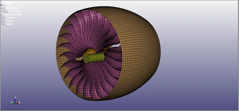
- Now I started from Material card.I make a fresh .k file and assigned material in that file.
- MAT001, Elastic material is assigned for bird and engine casing.
- MAT024, Piecewise linear plasticity is used for Hub.
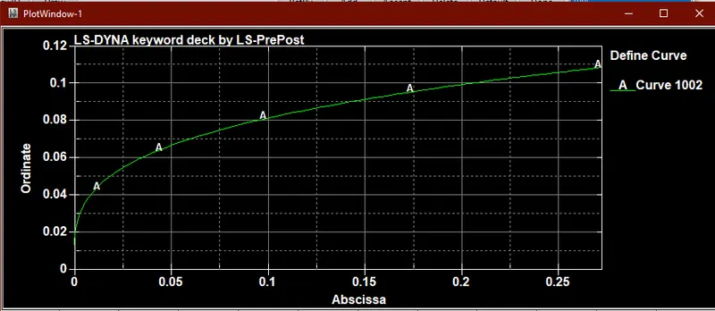
- Blade material is already provided with separate card(ALUMINIUM 4495).
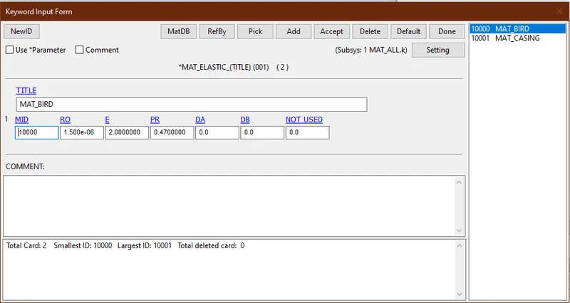
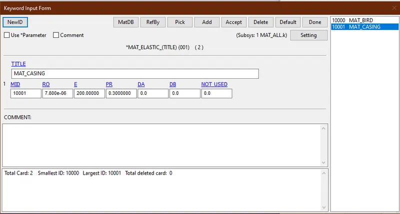
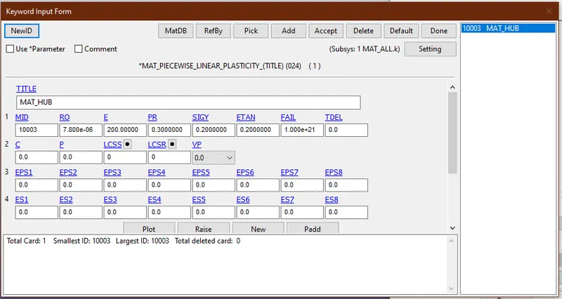
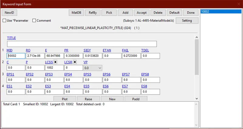
- Curve for Blade material.
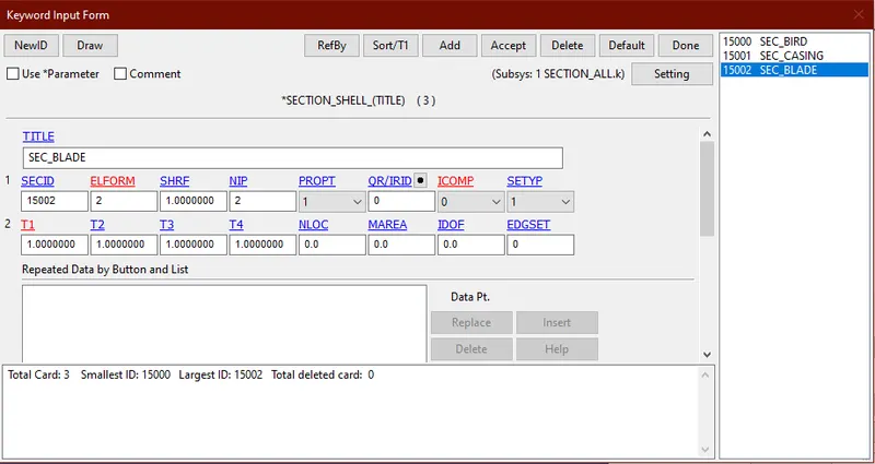
- Again as similar to above one new card is assigned only for sections and all the section card for different parts as assigned to that card with respective part ids.
- Section shell is defined with diffrent thickness for casing, bird and blade with elform 16(fully integrated).Solid section is used for hub with elfom4.
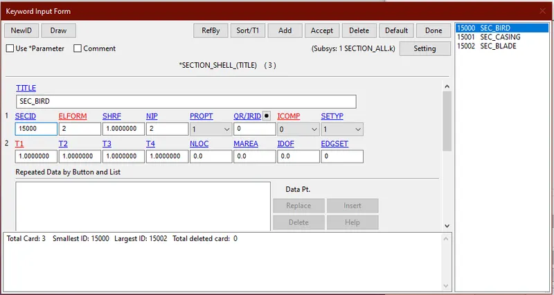
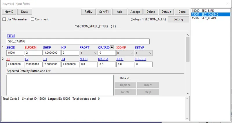
- Now as I define materials and sections its time for defining the contacts in the model.
- As similar process separate contact card is made and all the contacts are defined using part ids.
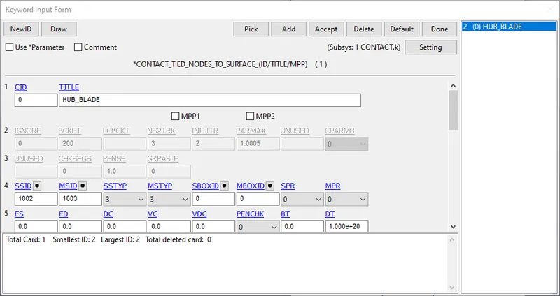
- Here two contacts are define one is TIED NODE TO SURFACE contact for blade and hub part where moving part blade is kept as slave and hub as master.
- AUTOMATIC SINGLE SURFACE is defined for all other parts like bird,blade and casing contact.
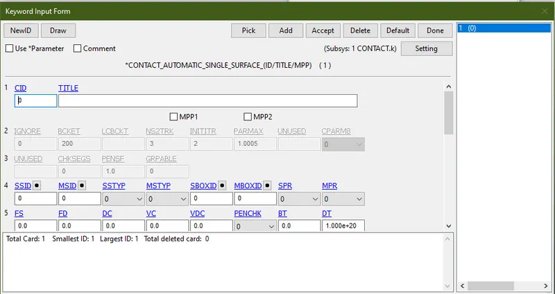
- In automatic single surface contact ssid and msid is given as 0 so that contact is assigned to all the remaining parts.
- Similarly Bounadry coditions are assigned by giving spc set to the casing,so that it will reamin fix in all direction when we provide angular velocity to the blades.
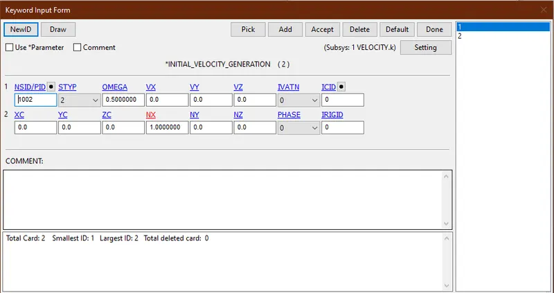
- Velocity generation card is asigned to boundary card and angular velocity is assigned to blade and x directional velocity is assigned to the bird.
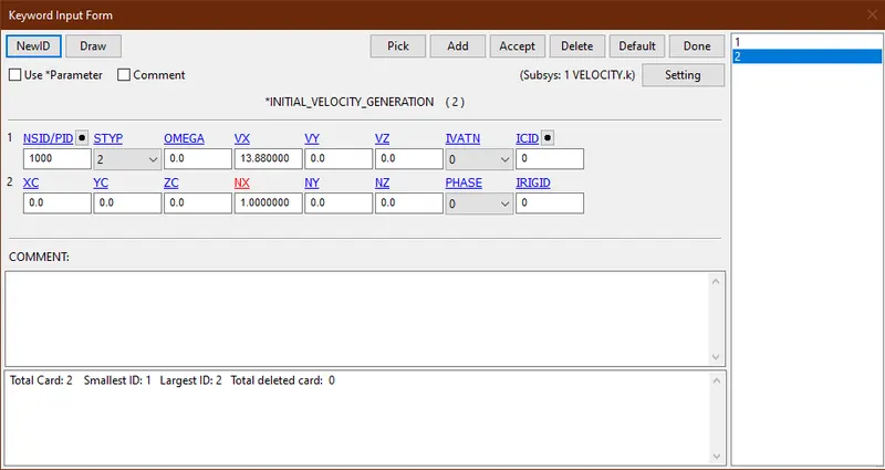
- Similary new .k file is made and control card is assigned,here only control termination is used and termination time of 10ms is provided.
- On the same .k file database cards are also added and necesaary outputs like GLSTAT,ASCII and MATSUM are assigned.Dt used for data base is 0.1ms.
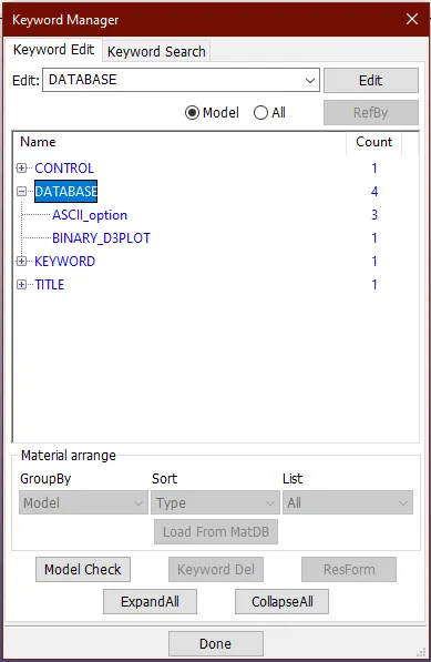
- After that all the cards kept properly in a discplined manner on a folder.
- Now another .k file is created and named as Main.k where all the other cards are called using the include card.
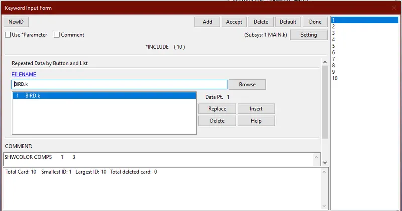
- In this card on the right hand side 10 cards can be seen which includes all the cards that are previously made including the parts.
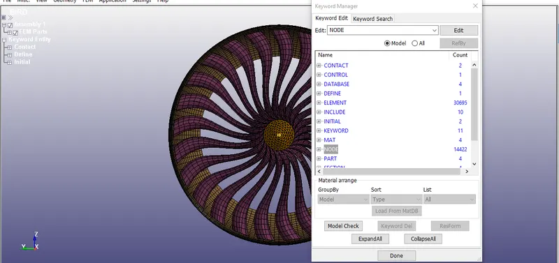
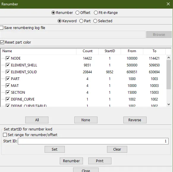
- Renumbering is done to renumber nodes elements and parts.
- Now its time to run the simulation without any adding mass and look for the results.
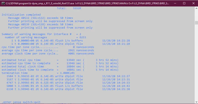
- Time here is showing 5 hrs and 14 mins.
- Dt = 6.25e-05
RESULTS:
- Effective plastic strain
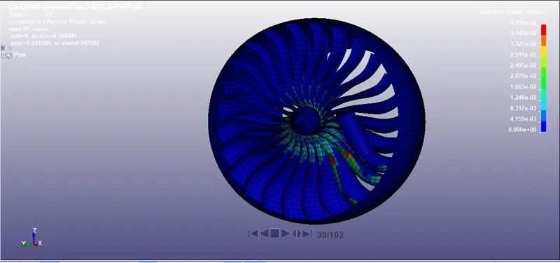
- Maximum plastic strain is 0.04159.
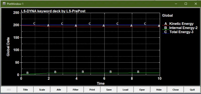
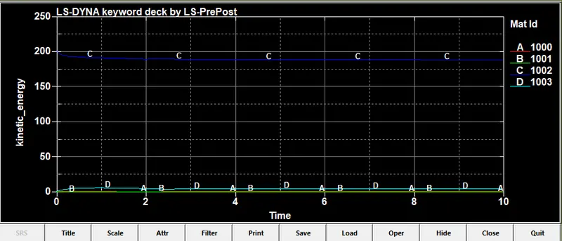
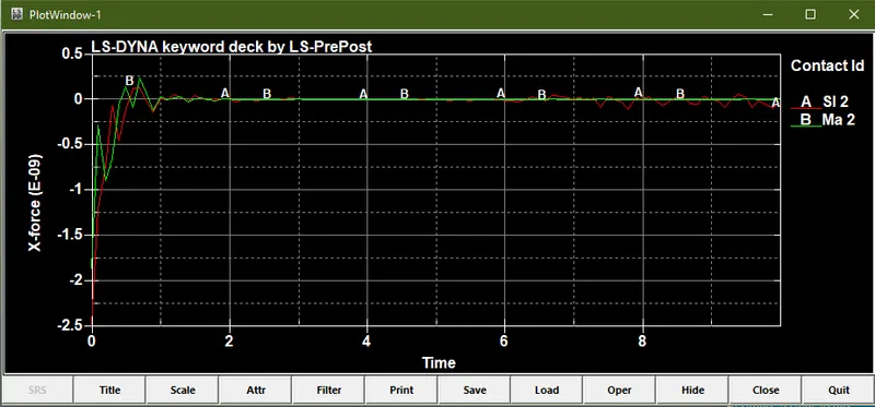
- ENERGY PLOT
1000- Bird
1001- Casing
1002- Blade
1003-Hub
Now mass is added in the simulation and then we look for results.10 % added mass is acceptable,Therefore we have to do trails to get that mark.
Here dt = 6.25e-05,
So control timestep is used with TSSFAC 0.9 and DT2MS more then 6.5e-05.
TRAIL 1
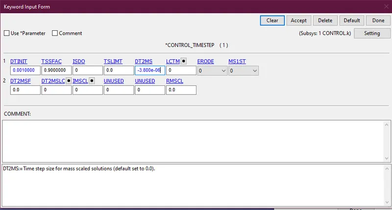
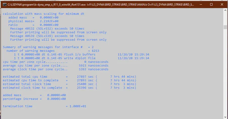
- Its showing increase in time therfore I have try with more values.
TRAIL 2
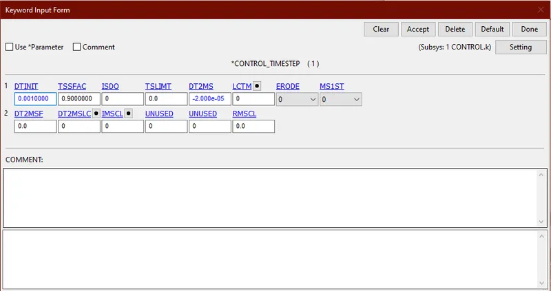
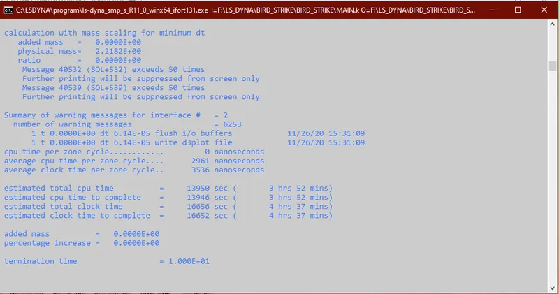
TRAIL 3
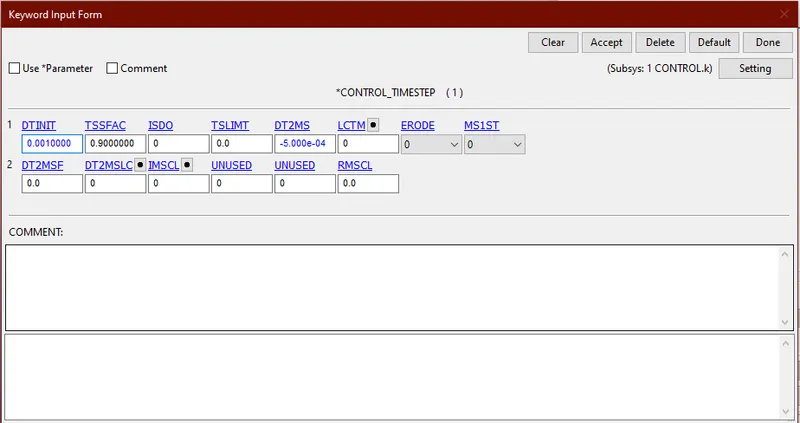
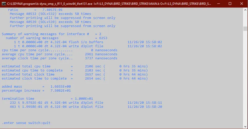
TRAIL 4
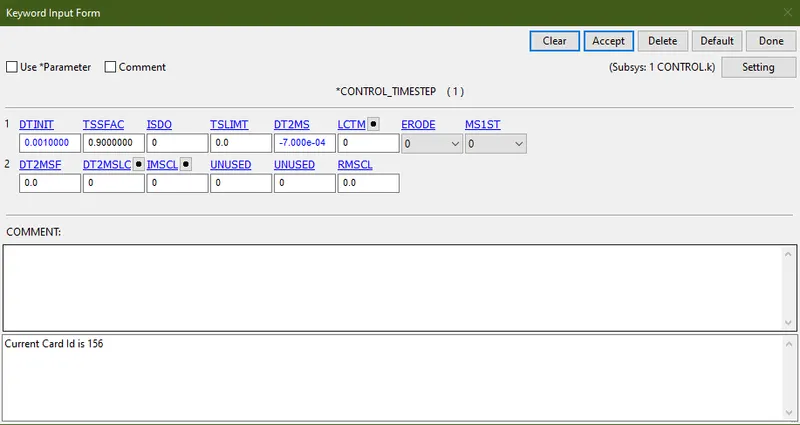
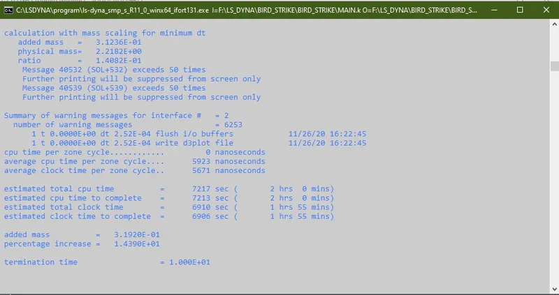
TRAIL 5
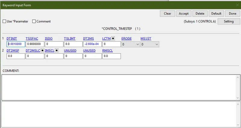
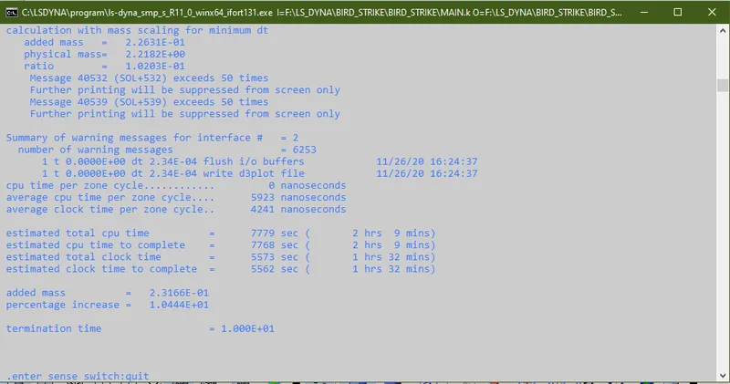
- Finally after 5 trails I got 10% add mass value at DT2MS -2.6e-04.
RESULTS AFTER ADDING MASS:
- Effective plastic strain
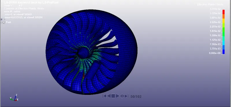
- Here maximum plastic strain is 0.0375.
PLOTS:
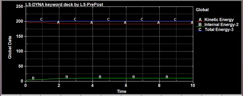
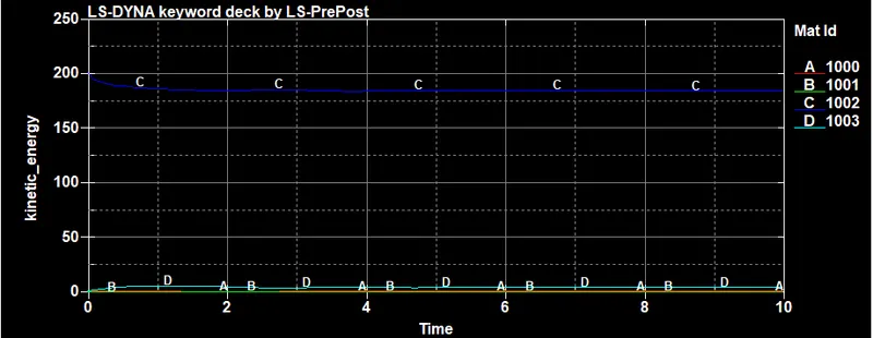
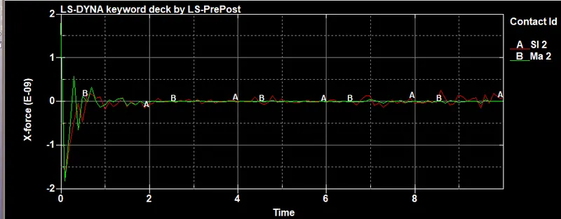
- Plots are similar to above case.
ERRORS WHILE SIMULATING AND DEBUGGING THEM:
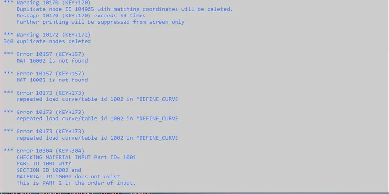
The above error shows up while simulating.This kind of error occurs because of including same material in two parts.Therfore duplication happens.
For debugging this error I use only single material in single part and make seperate material card for no duplication.
ANIMATION VIDEO:
CONCLUSION:
- In this project I learnt about making diffrent cards and include them in a single file.
- Learnt about how to renumber nodes, parts and elements in discplined manner.
- Effective plastic strain value decreases after adding 10% mass in the model.