Bird Strike - Project - 2
AIM
Setup the deck for Bird Strike Simulation and evaluate the results
CASE SETUP
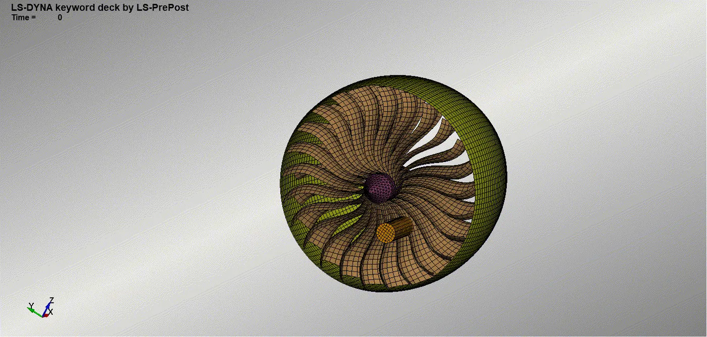
We are having bird strike simulation model with us.We need to choose each components like bird , casing, blades , and the hub.EAch of these needs to be saved as differant differant keyword file.Then again open a Ls prepost and save that as main.DYN which will be the main keyword file of the bird strike simulation.Again we can open that keyword file in LS Prepost then using the INCLUDE command we call all these keyword files.Along with it we are provided with a material model keyword file for the blades , so we will be including that file too.each of these files will be saved to the main.DYN file.the file path is edited as ../ to tell the solver to check the directory by going once back.This will enabe us to have the files properly setup in a folder and we can copy that folder to whatever location we need to and at the same time the files will gets properly located by the include card itself.
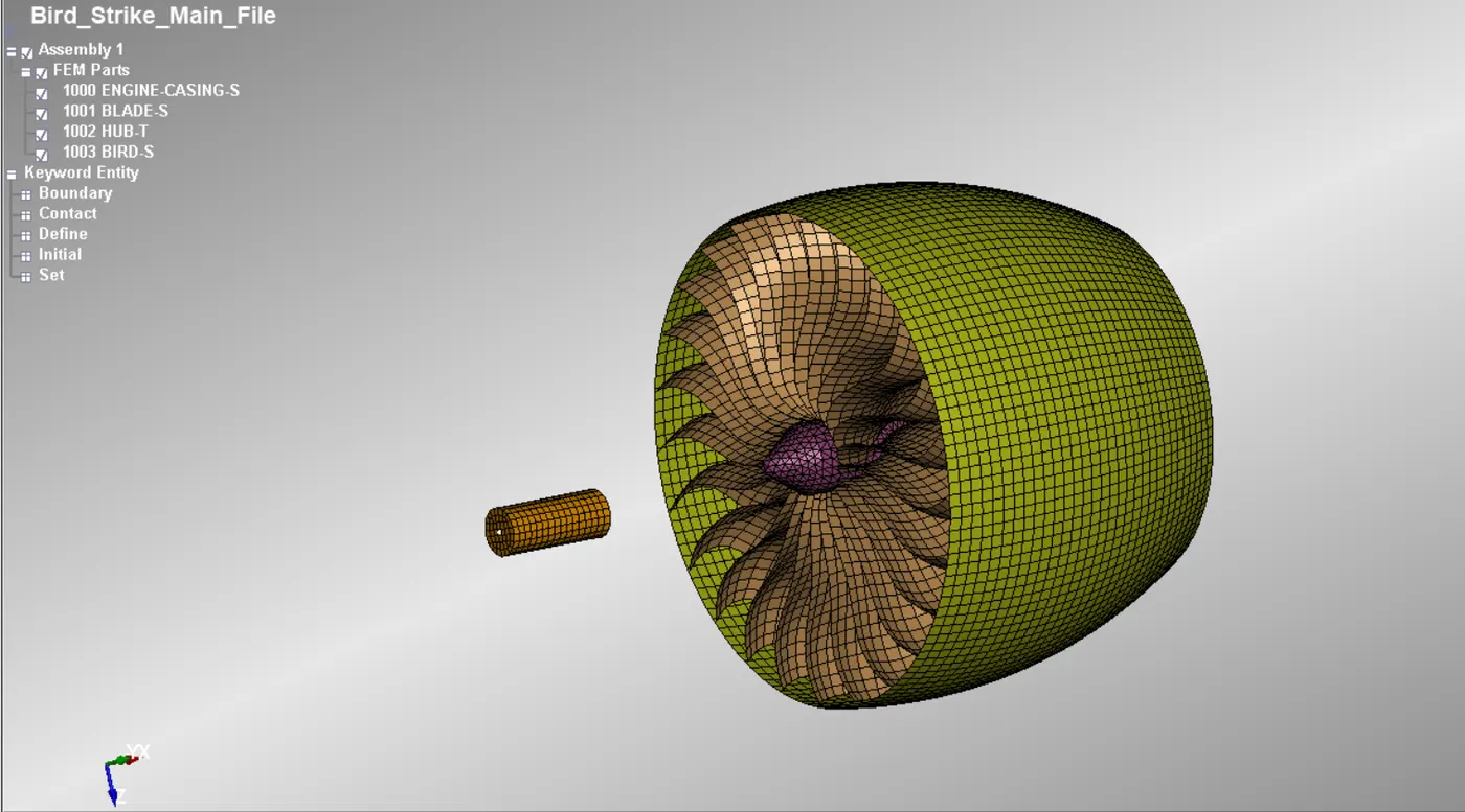
Fig 1 Bird strike model
And we need to open that main.DYN file and now we are having 5 subsystems.But now w need to create anothr subsystem which saves the boundary conditions and contact informations etc.First open a ls prepost and save that as the keyword file as Boundary comditions.k file.Then open the main.DYN file and include that boundary condition keyword file into this main file.Then save it and again open that file in LS prepost.
We then setup the deck for the impact simulation of the bird strike.First we will be using the steel material properties to create the elastic material model card.And this should be saved in the boundary condition and other.k subsystem.For defining the part we need to create section card also.Since the hub is having solid elements and rest everything is shell elements.
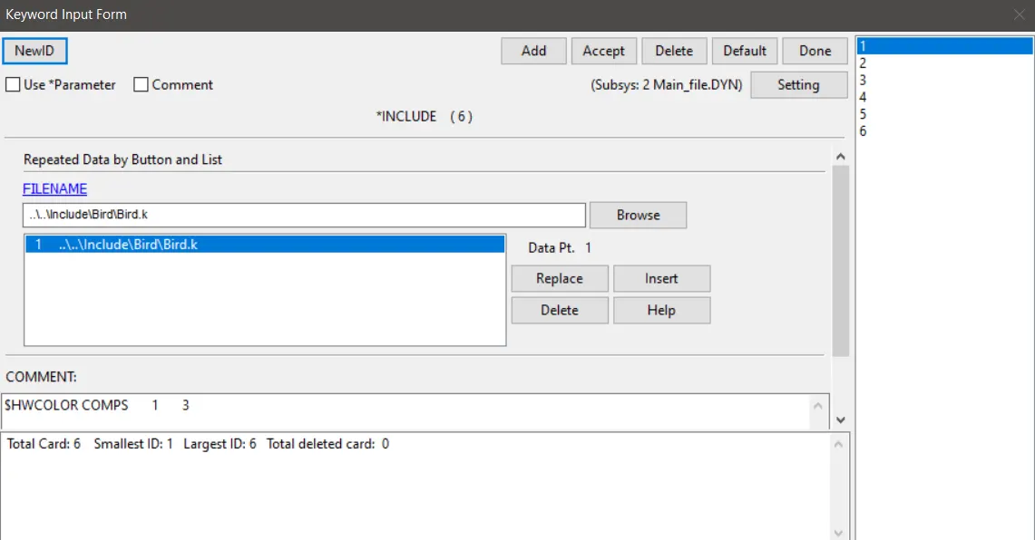
Fig 2 Include Card
Shell section card needs to be created with ELFORM as 16 which is fully integrated elements which will eliminate the possibility of hourglass formation.Then again create another SOLID section card which will be havinf ELFORM as 2.Both of these section card needs to be saved in the boundary condition and other.k subsystem.
So we now have the marterial models and the section card for defining the part.We define the hub part with solid section card and the elatic material model.Blades needs to be defined with the given piece wise Linear Plasticity material Model. and the shell section card.All the other parts needs to be defined with the shell section and the elastic material model card.And these part definitions all needed to be saved in the boundary condition and other.k subsystem.
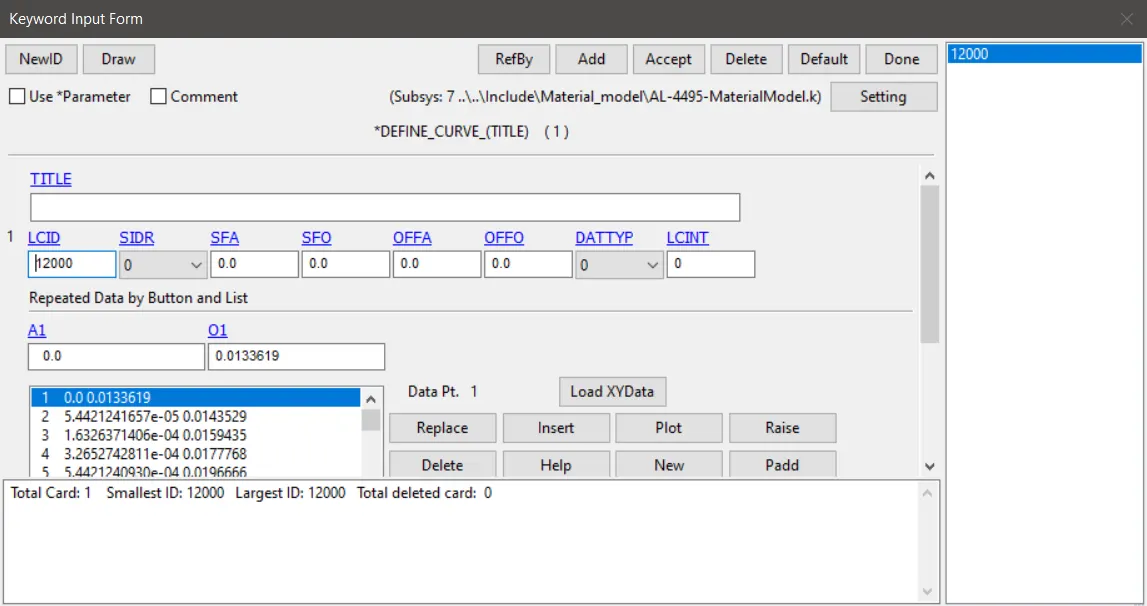
Fig 3 Linear plasticity material curve define curve card
We need to fix the casing at one end.For that we need to create a SPC.For that we create a NODE SET at one end of the casing.then we will be adding that to the SPC card and we arrest the degree of freedom in all directions.
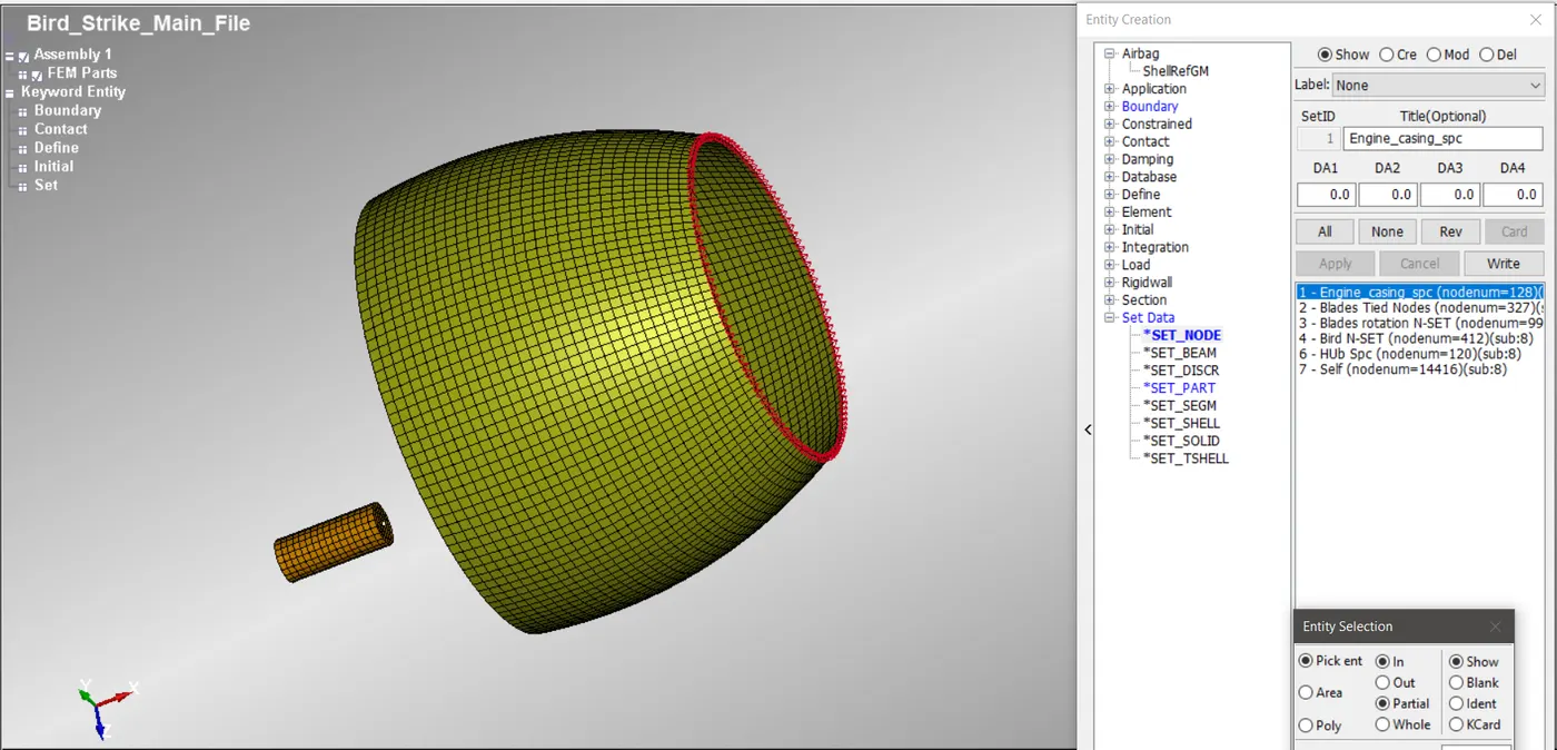
Fig 4 Engine casing spc nodes
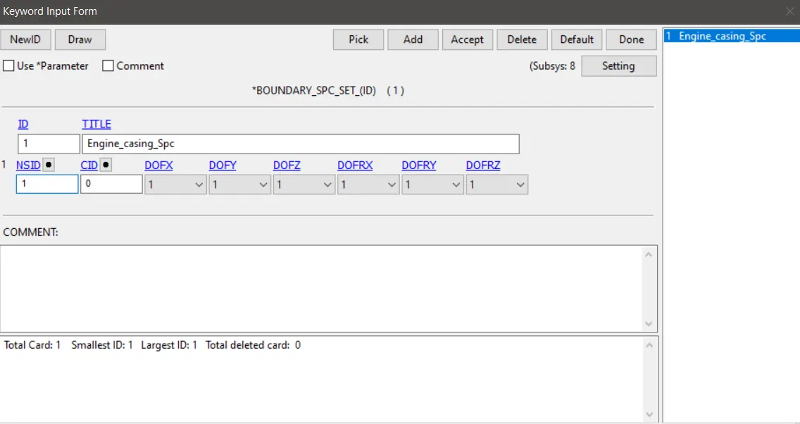
Fig 5 Assigning degree of freedom for spc engine casing
Then we can see that the hub and the blades not fixed but in real scenario we can find that hub and blades will be rotated together.In the same way we need to replicate that in simulation.For that we create a TIED NODES TO SURFACE contact between the blade nodes and the HUB.We provide Slave set as Node set and the Master set as HUB part set.This contact also should be saved in the subsytem of boundary conditions and others.
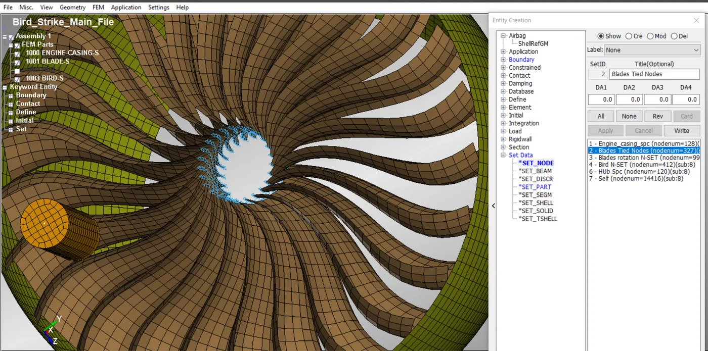
Fig 6 Blades tied nodes set
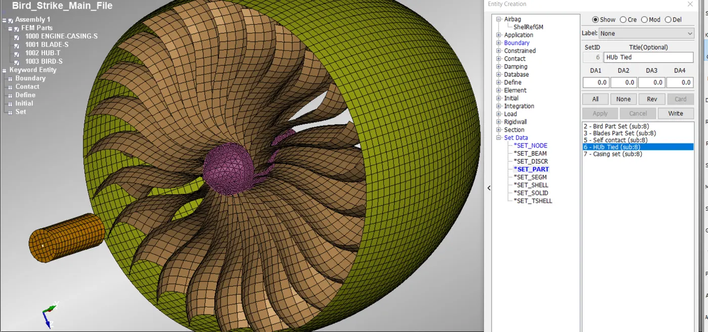
Fig 7 Hub part set
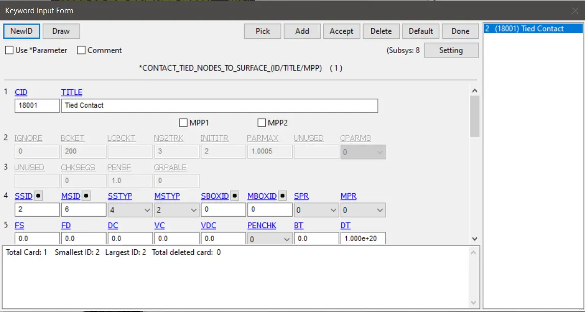
Fig 8 Contact tied nodes to surface contact card
Since we need to simulate the bird striking the blades ,and the bird striking the blades should cause the failure of the blades. As the failure of blades happen they may came in contact with the other parts.So we should create a self contact between all the nodes in the model.along with the bird nodes.These nodes will be selected as the slave nodes of the Contact Automatic Single Surface .This contact also should be saved in the subsytem of boundary conditions and others.
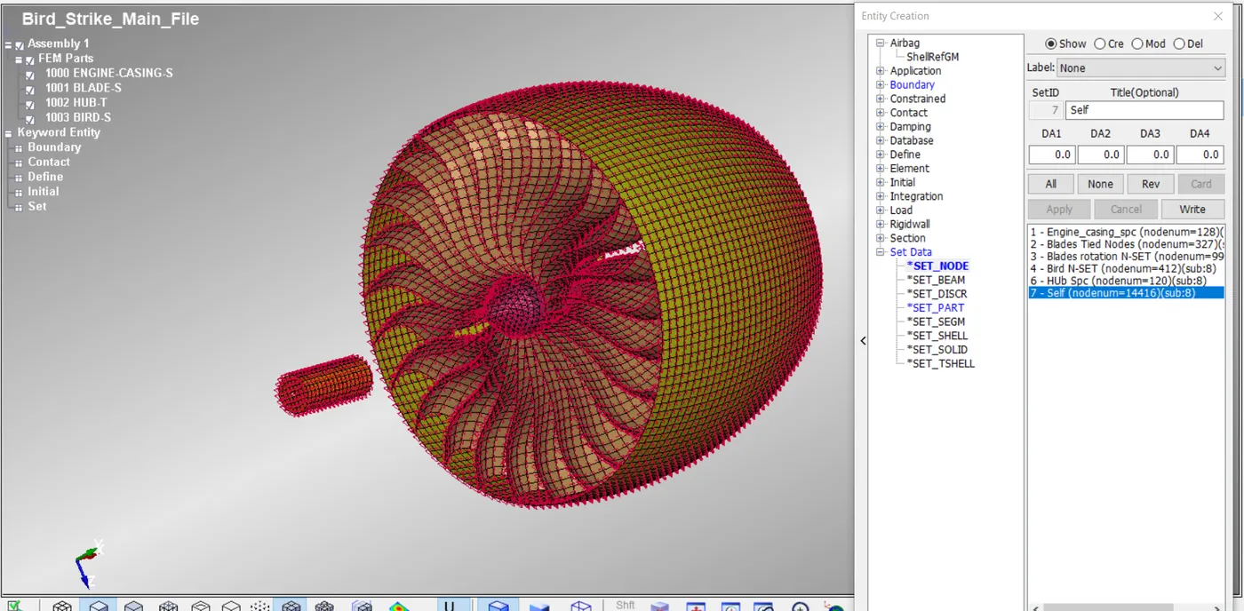
Fig 9 Self contact Node set
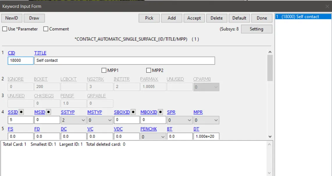
Fig 10 self contact contact card
The velocity of the Bird and the Blades and the hub combined can be given using the velocity Generation card.In velocity genration we need to create a Node set of the bird and other node set of blade and hub combined.Using the velocity gneration card omega value of 0.4 rad /msec is used to provide the rotation for the blade and the hub combination. Similarly the bird node set can be provide velocity of 50 mm/msec .
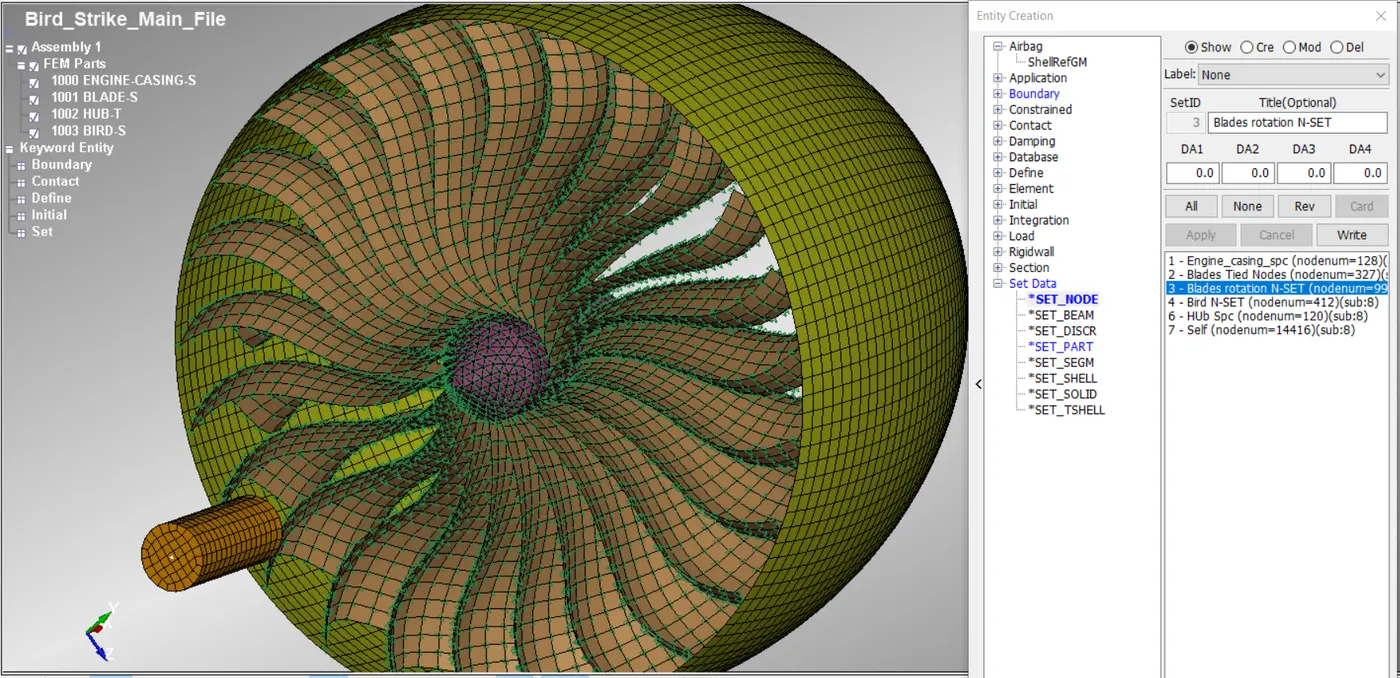
Fig 11 blades and huub nodes combined nodes set
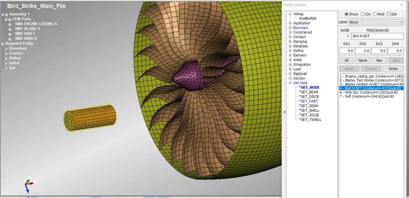
Fig 12 Bird part node set
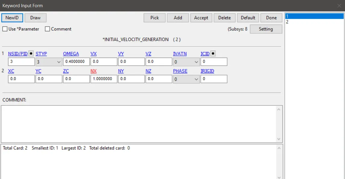
Fig13 Intial velocity generation card for blade rotation
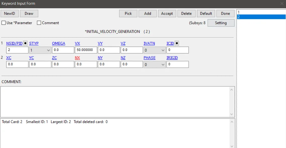
Fig 14 Intial velocity generation card for translational velocity for bird
Also we need to create a part set for the casing and also fpor the blades because there is a possibility of contact happens with the blades and the casing.So we can make use of Automatic contact Surface to surface .And here we use the casing as the master and the blades as the slaves.
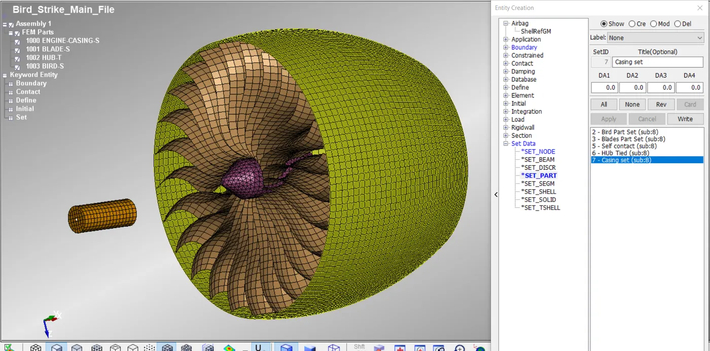
Fig 15 Engine casing part set
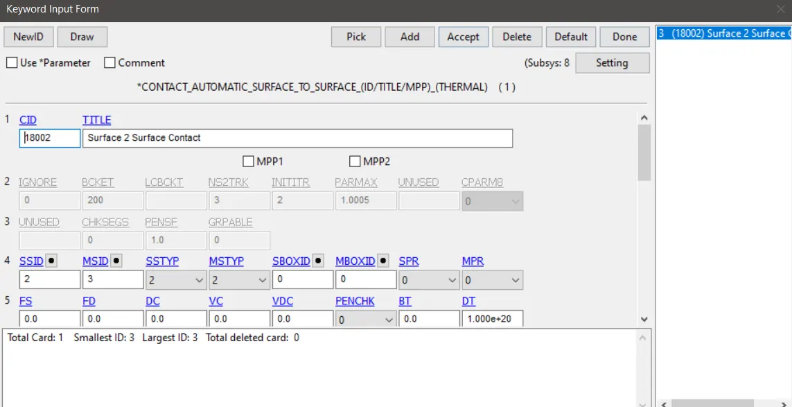
Fig 16 Contact surface to surface contact card
Then the other card like Control Termination ,database D3Plot , Database extent Binary , and the other ascii options such as GLSTAT and MATSUM.
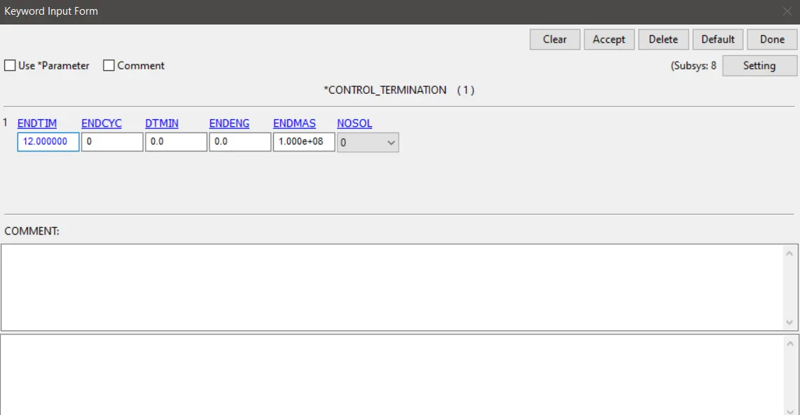
Fig 17 Control terminatiom card
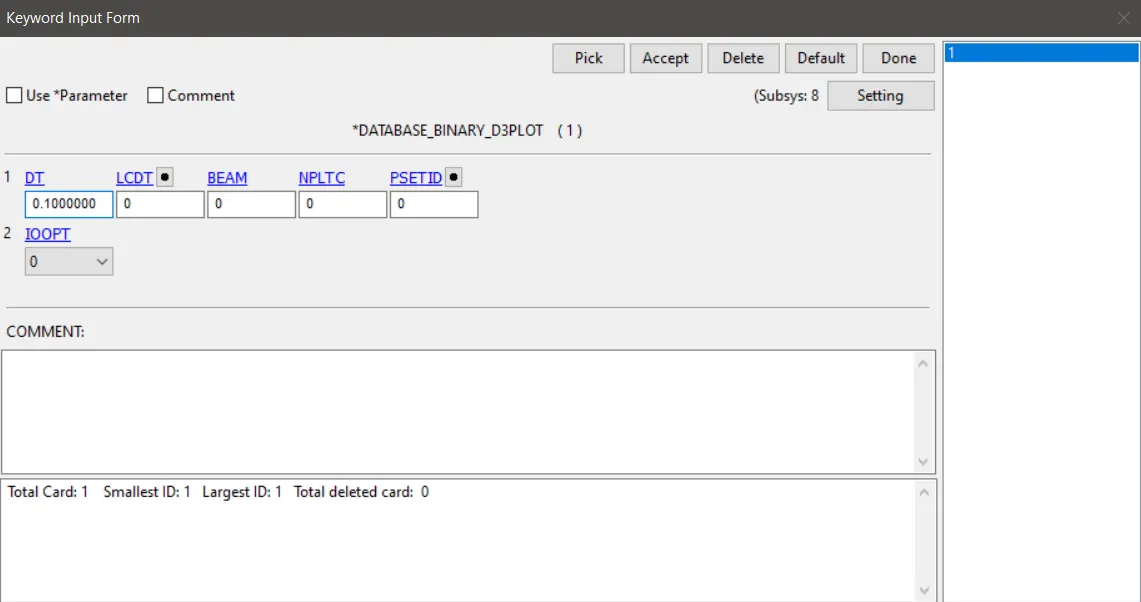
Fig 18 Databse Binary D3plot card
Then for proper understanding of the card we ned to make renumber the card.This can be done using Model >renumber > Select the entity >Give the start Id > Set <> renumber
Here the renumbering order follows is as follows:-
Nodes - From 100000
Element Shell - From 500000
Element Solid - From 700000
Part - From 1000
Material - From 10000
Section - 11000
Define Curve - 12000
Node Set - 13000
Part set - 14000
Contact - 18000
DEBUGGING
When we use the omega value of the blades as extremly large like 15 rad/msec which is a huge value, so that the centrifugal values are very large which will overcome the yield stress of the blade marterial which will make the elements exploding in radial direction.But this won't happen in real case as this is not a real case value of omega value.
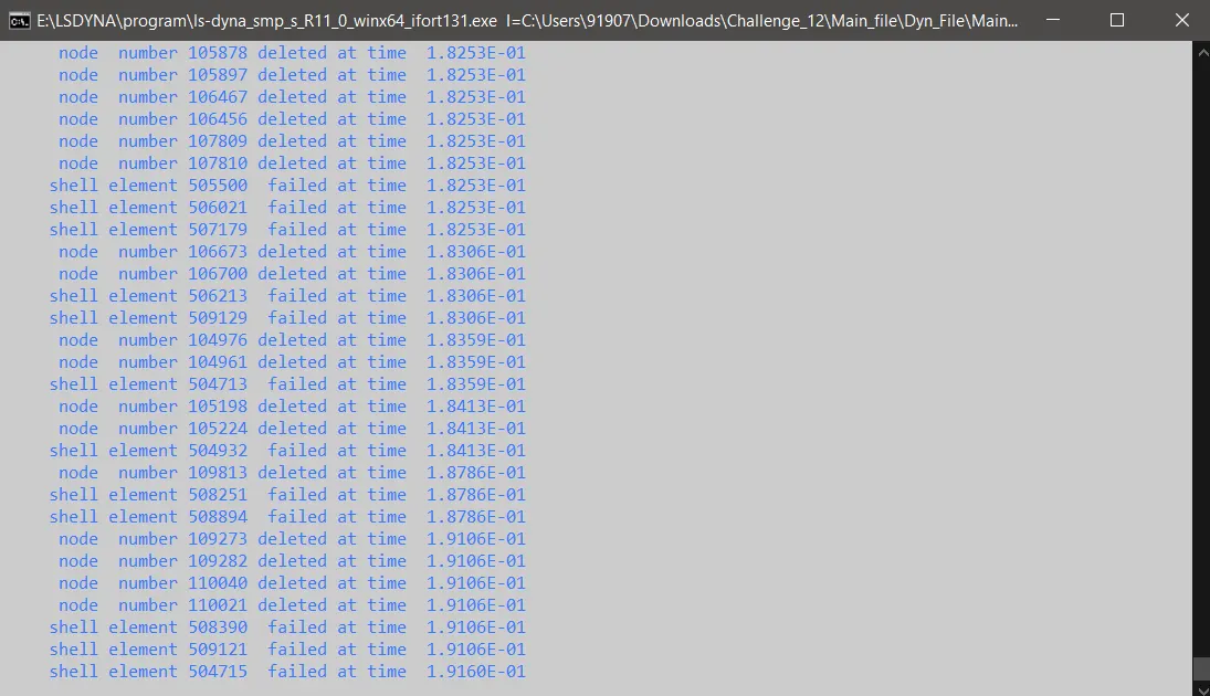
Fig19 Shell elements faling due to high omega value
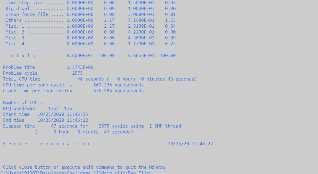
Fig20 Error termination due to all element of blades failed
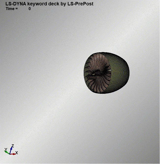
Fig 21 Elements exploding dur to high omega value
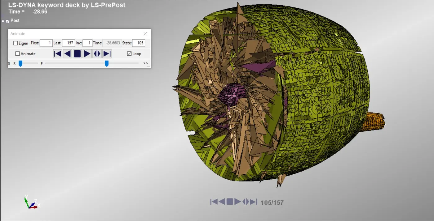
Fig 22 Elements exploding due to high omega and error in contact creation
RESULTS
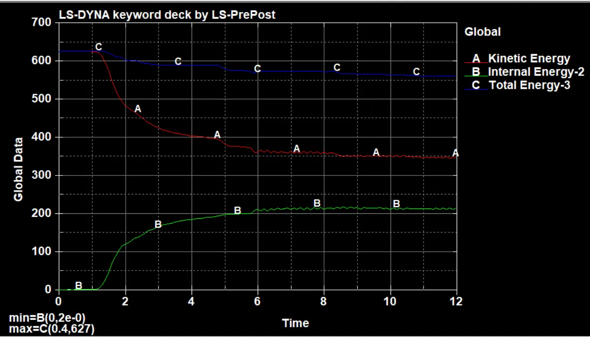
Fig 23 Energy curve of the bird strike simulation
As we guessed the energy curve is showing what we expected.The inernal energy is moving up due to high deformation happens to the blades material at the same time the kinetic energy is restricted and coming down as we can see that the bird is slowing down due to the collision and the blades are also slowing down ,that is making the kinetic energy reduced and the total energy remains constant which is the sign that the simulation is giving us the proper results.
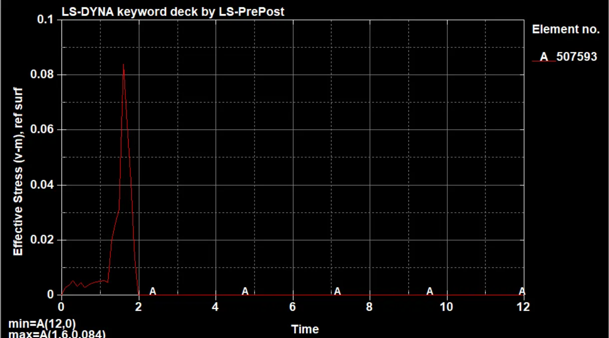
Fig 24 Effective stress on a blade element
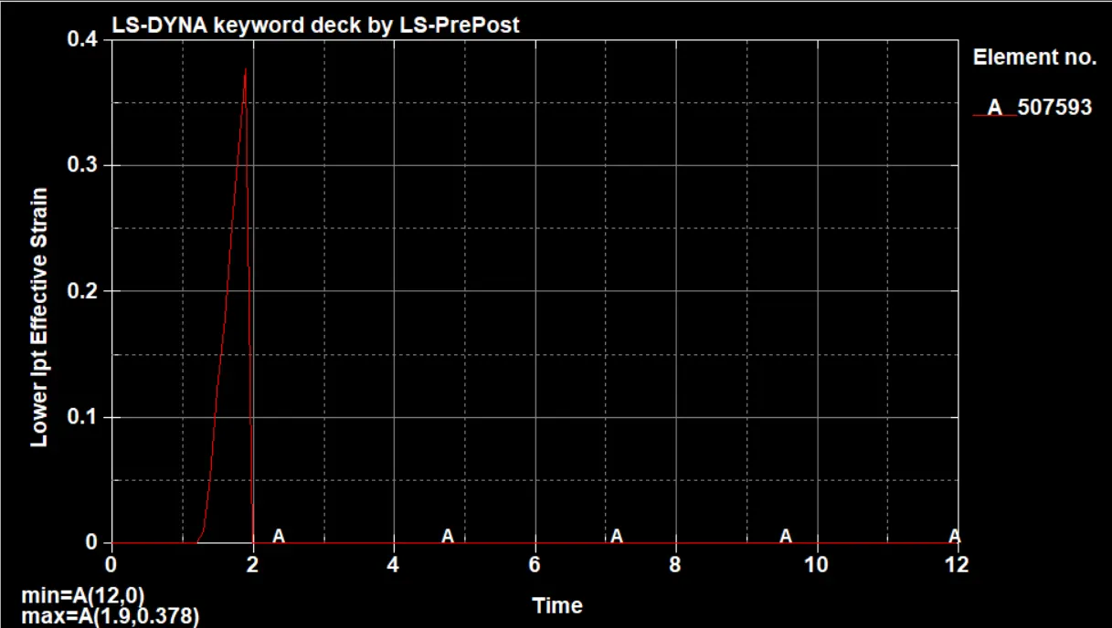
Fig 25 Effective strain on blade element
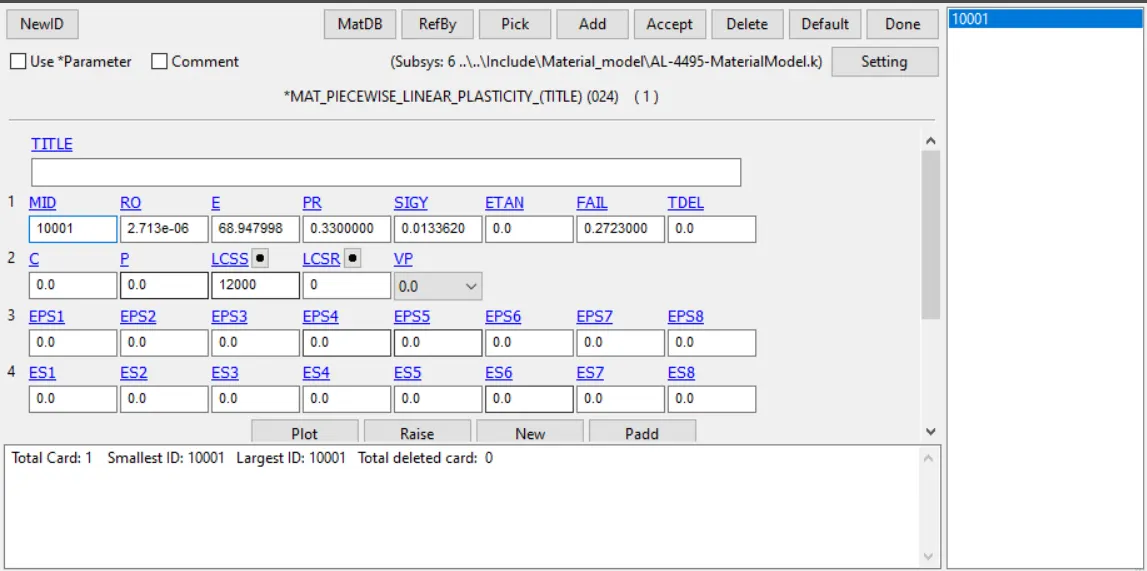
Fig 26 Linear piecewise plasticity material card for blades
Here we can see that the yield strength value is just 0.013 Mpa but from the simulation we can see that the as soon as the bird strikes with high velocity to the blades the blades gets plastically deformed and the plastic strain value increases.As the derormed elements defoms to the level that strain overcomes its failure strain which deletes the element from the model, so that the deleted elements strain value is shown as zer and the bird after passing the blades and end up hitting the casing so that the strain va;lues will bezero as there is no deformation happens therafter.Here the graph is showing the effective strain value which will be having only the plastic strain componenet since after the casing gets defoemd due to bird hiotting on it,there is some elastci deformation happens to the casing and bird but there is no plastic deformation happens there.So that is why the graph is showing like zero after the 2 milli second as there is no plastic deformation happens thereafter.
So here the blades ae destroying by the bird as soon as the bird hits it.but in real life we dont want this to happens ,eventhough we have additional backup engine we dont want our engine to malfuction, so so many reasearches have done on this and the way to prevent this to happens bird traffic at the regions where the aircraft is having less altitude in regions where the flight is taking off and lifts up,this happens near to the runway regions. So many bird traffic is done near to it.As the simulation suggests the thickness of blades to be increased so that we can stregthen up the material of the engine blades to prevent the possibility of birds to make failure to the blades. Aerofioil shape changes cannot be done as it is optimized to get proper air flow through the baldes .So waht we can do is material change and the thickness change.Here can optimize the thickness and make the blades strong to the bird strike.
Link For the files
https://drive.google.com/drive/folders/1LI7App3v1Oemz-9NhIDqedByw8sNrrKQ?usp=sharing