Bird Strike - Project - 2
#13 // Project – 2 Bird Strike in Aero Engine.
AIM:
In this project, we have performed the bird strike analysis using the Lagrange formulation. The bird is simplified in this case because the shell element is used and the material used for the bird is elastic material. Except that everything is kept quite similar to the actual bird strike simulation.
OBJECTIVE:
- Simulate a bird strike situation using given models with appropriate material models as required.
- Establish a numbering system for the Ids of all the keywords with proper ranges for multiple cards.
- Distribute the given model in individual keyword files for various components as well as analysis sub-components.
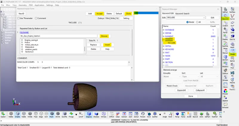
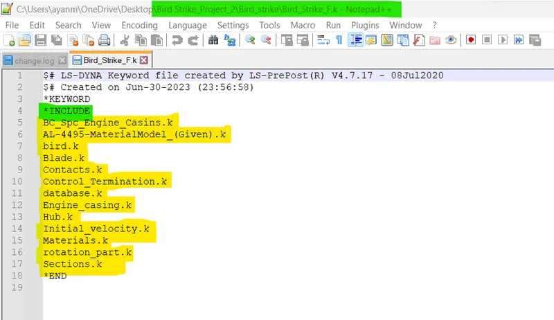
- Use the ‘Include’ keyword to put these keyword files together and run the analysis such that moving the folder with these files won’t cause a problem with the analysis.
- Use mass scaling to minimize the analysis time and its effect on the outputs. (If needed)
INTRODUCTION:
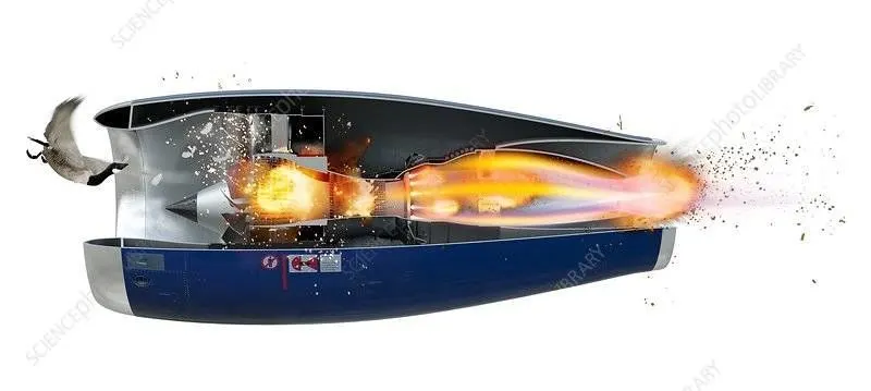
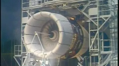
A bird strike is strictly defined as a collision between a bird and an aircraft that is in flight or on a take-off or landing roll.
Bird Strike is common and can be a significant threat to aircraft safety. For smaller aircraft, significant damage may be caused to the aircraft structure, and all aircraft, especially jet-engine ones, are vulnerable to the loss of thrust which can follow the ingestion of birds into engine air intakes. This has resulted in a number of fatal accidents.
Bird strikes may occur during any phase of flight but are most likely during the take-off, initial climb, approach, and landing phases due to the greater numbers of birds in flight at lower levels. Since most birds fly mainly during the day, most bird strikes occur in the daytime. Most fatal are the ones in which birds get ingested into the engines and damage the rotors and cause explosions.
Problem statement:
This is a classic nonlinear transient dynamics problem similar to car crashes and mobile drops. While accurate modeling of the problem requires advanced techniques such as SPH (Smooth Particle Hydrodynamics), this problem can be solved using a generic explicit solver. Here is the information required to model the phenomenon.
- The blades should rotate at a constant velocity but the casing should remain stationary.
- The cylindrical bird model should travel along its own axis and hit the blades.
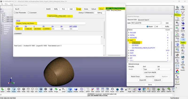
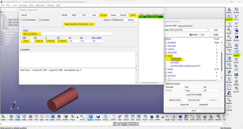
- Use elastic material for the bird (2000MPa) and the casing (200GPa). The material model for the blades is attached.
- The velocity of the engine blades and the birds can be chosen so that blade failure can be seen within a short span of time.
Apart from this, a meshed file of the model was provided and it was asked to keep all the parts, keywords like contacts, boundary conditions, material data, and control files into separate key files and unite them together in the main file.
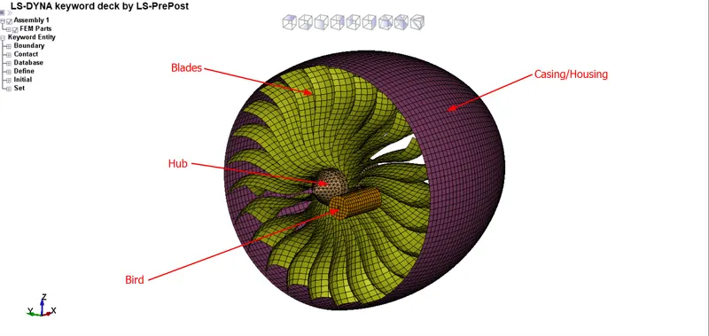
CAD Model:
PROCEDURE:
1) Part Creation -
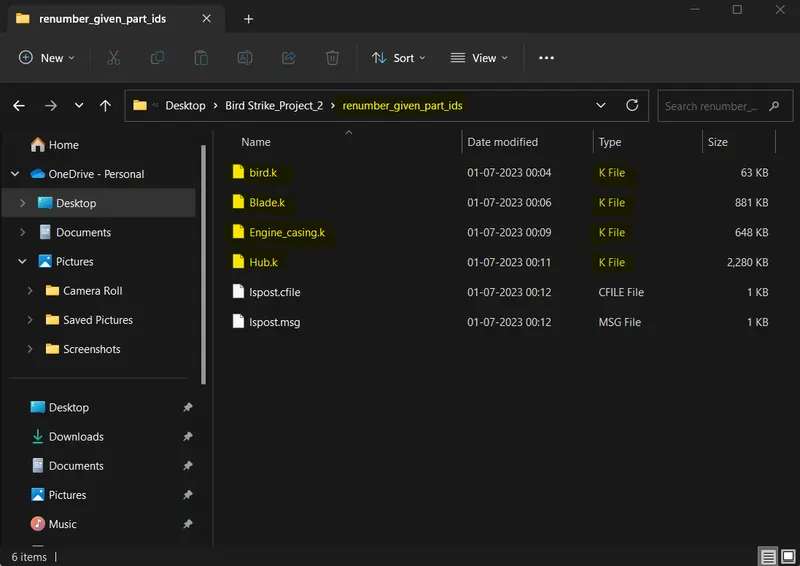
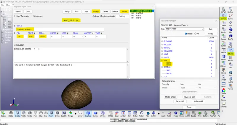
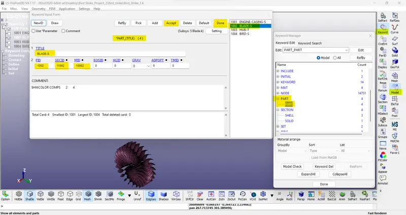
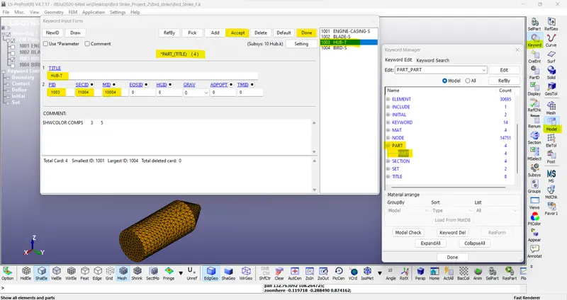
Open the BIRD_STRIKE.k file in LSPP. Here we see that there are four parts available (Hub, casing, blades, and bird). New “.k” files are created individually for each part. For that go to PART and select one part, the remaining parts are deleted and saved as a particular file name.
2) Renumbering -
Renumbering of nodes, elements, and parts is very useful when we work on a very complex model.
-In our question, we provide the number starting from:
- i) nodes: Start from 1,00,000
- ii) Elements: Start from 5,00,000
- iii) Parts: Start from 1,000
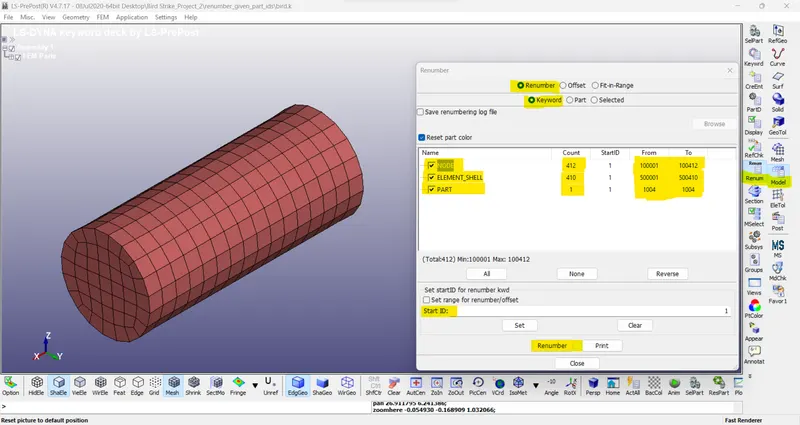
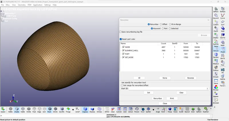
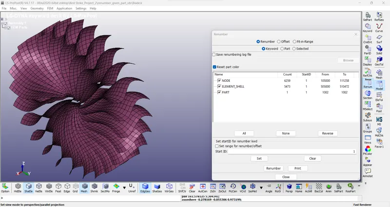
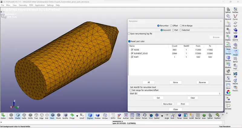
For the renumbering go to Model and Part > Renumber. After that change the value individually by toggling on the checkbox for the entities, then click on Set and Renumber.
- Now go to Model on the right toolbar and under renumbering input the appropriate start ID for Nodes, elements & Parts:
/4// Bird ->
|
Components |
Start ID |
End ID |
|
Node -> |
100001 |
100412 |
|
Element -> |
500001 |
500410 |
|
Part -> |
1004 |
1004 |
/1// Engine Casing ->
|
Components |
Start ID |
End ID |
|
Node -> |
100500 |
104596 |
|
Element -> |
500500 |
504467 |
|
Part -> |
1001 |
1001 |
/2// Blades ->
|
Components |
Start ID |
End ID |
|
Node -> |
105000 |
111258 |
|
Element -> |
505000 |
510472 |
|
Part -> |
1002 |
1002 |
/3// Hub ->
|
Components |
Start ID |
End ID |
|
Node -> |
112000 |
115982 |
|
Element -> |
515000 |
535843 |
|
Part -> |
1003 |
1003 |
3) Material and Section Creation -
First of all, open all the part files created in LSPP one by one. Then create the material and section card separately. Here we use the unit system Kg, mm, ms.
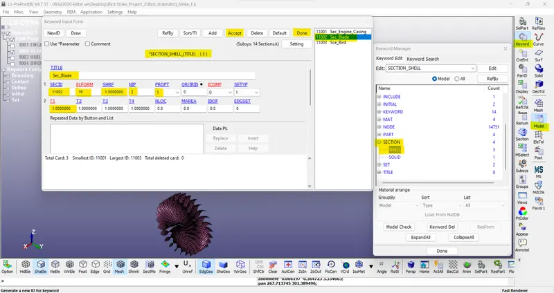
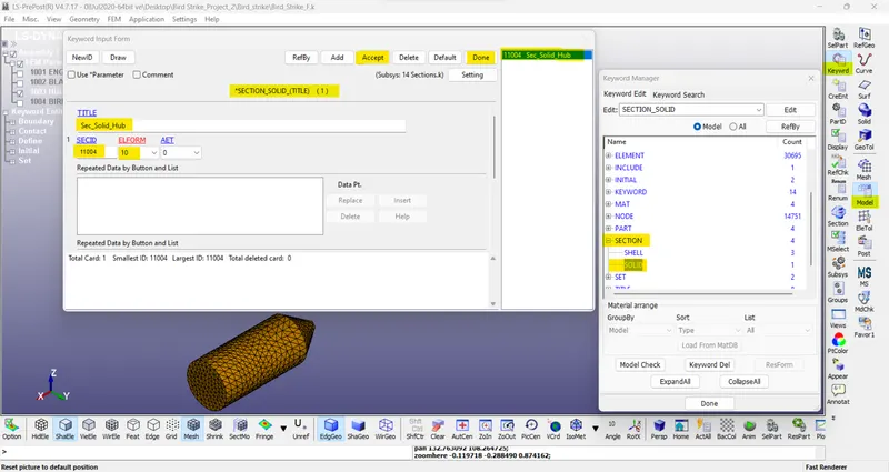
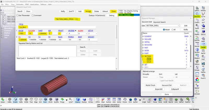
Bird, Blade, and Casing are SHELL elements. Hub is the SOLID element.
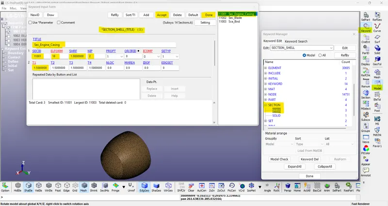
Element formulation for shell is 16(fully integration) and for solid is 10 (1-point tetrahedron)
thickness for --
- bird = 1.0 mm
- blade = 1.0 mm
- casing = 1.5 mm
- Casing: For casing ELASTIC steel material is defined.
A. Material Card:
B. Section Card:
C. Part:
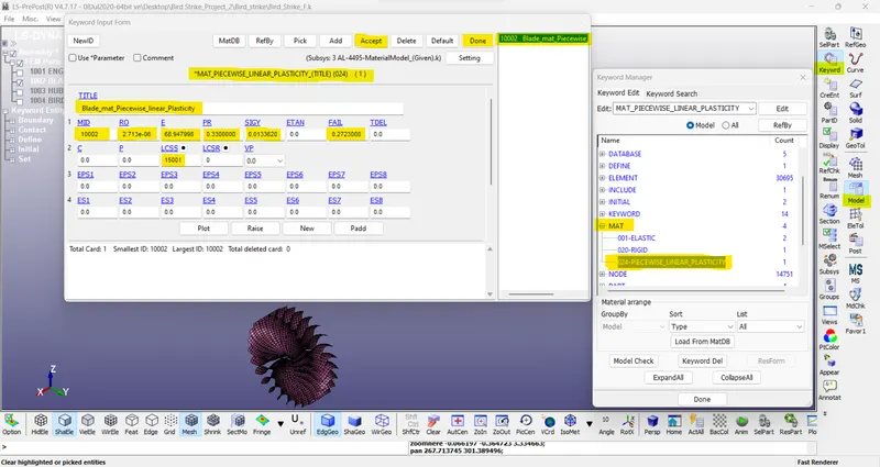
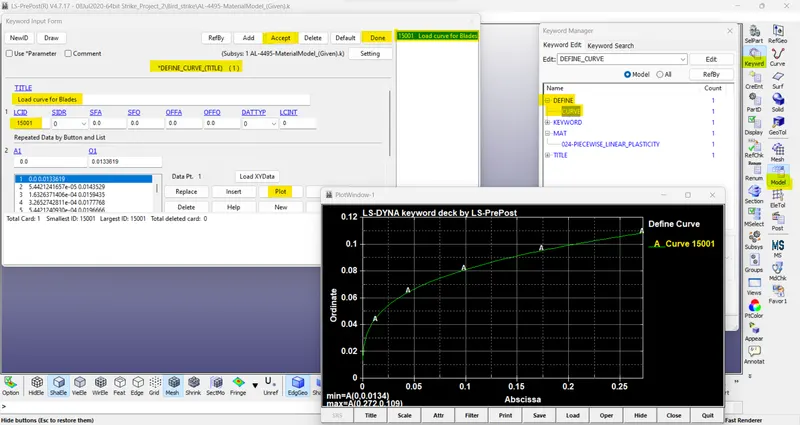
- Blades: In this model, elastoplastic material (MAT_24 LINEAR PIECEWISE PLASTICITY) card has been chosen (given as ‘AL-4495-MaterialModel.k’). ALUMINIUM is selected.
For blade material, a data curve is available in the question. So, we use that data for the creation of material.
A. Material Card:
B. Load Curve Card:
C. Section Card:
D. Part:
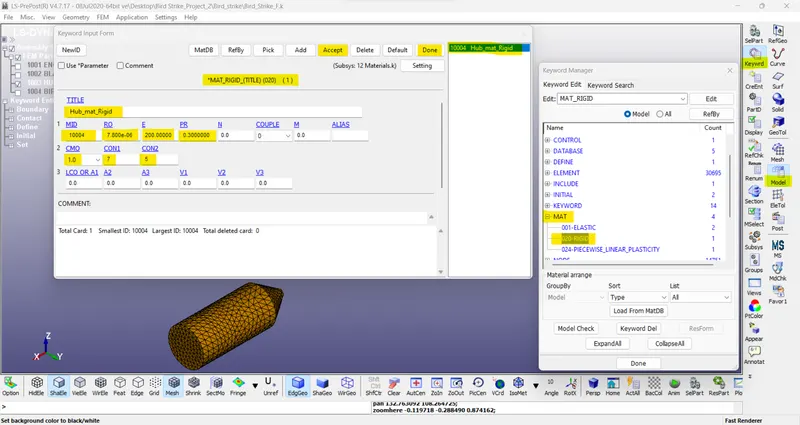
- Hub: We use steel data for creating the hub material card. In this model we only focus on the blade so defined the rigid material for the hub because it provides the additional benefits of constraining the part in the required degree of freedom otherwise, we have to define the cylindrical joint between the casing of and the hub so that the hub must be maintained in position. For the hub, we create a SECTION_SOLID card.
A. Material Card:
B. Section Card:
C. Part:
Bird: Generally, in bird strike modelling bird is a challenging task because it consists of bones blood and organ, so for simplicity, In the Aerospace industry bird is modelled as 90% water and 10% air-like gelatine material.
In our case, the bird is modelled with lower density and higher Poisson ratio and lower young modulus.
A. Material Card:
B. Section Card:
C. Part:
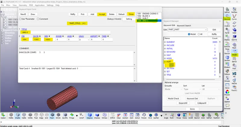
4) Creating Entities -
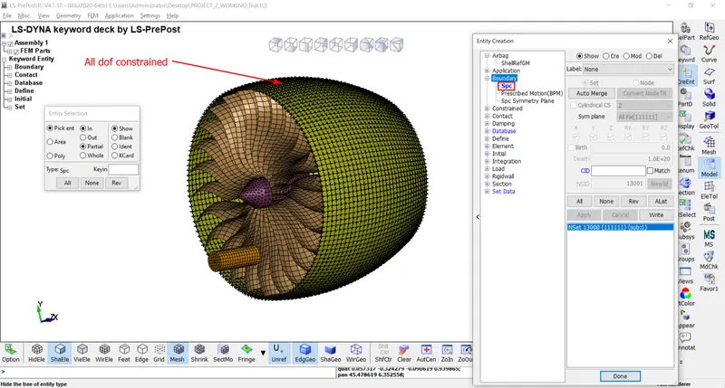
A. SPC:
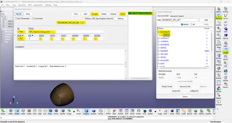
Go to Create Entity > Boundary > Spc > Create. Here 1 SPC is created with casing.
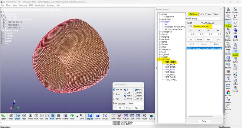
B. Node Set:
Go to Create Entity > Set Data > *SET_NODE > Create.
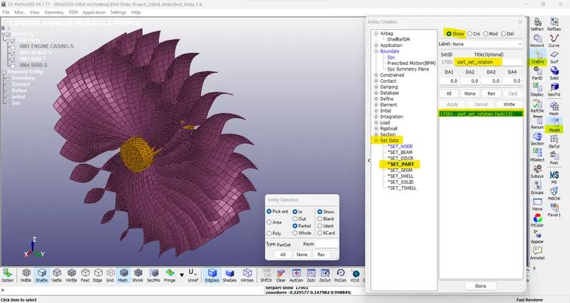
C. Part Set:
Go to Create Entity > Set Data > *SET_PART> Create. Here 2-part sets are created one with hub and blade.
5) Boundary Conditions -
*SPC_SET card is defined for the casing where the motion of the casing is restricted in all directions.
6) Initial Velocity -
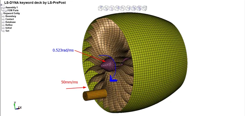
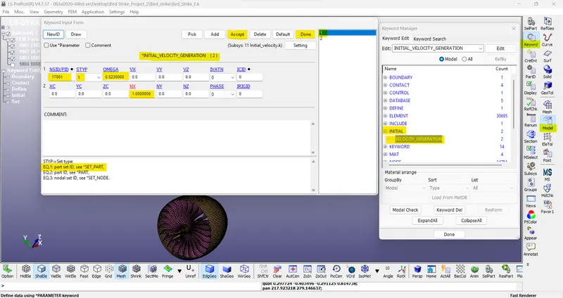
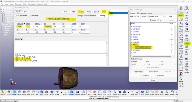
An initial velocity of 50 mm/ms is given for the bird in the X-direction and a rotational velocity of 0.523 rad/ms is given for the hub and blade as a part set using *INITIAL_VELOCITY_GENERATION card.
Part-set (Blades & Hub) with rotational velocity-
Bird part with X-directional initial velocity-
7) Contacts -
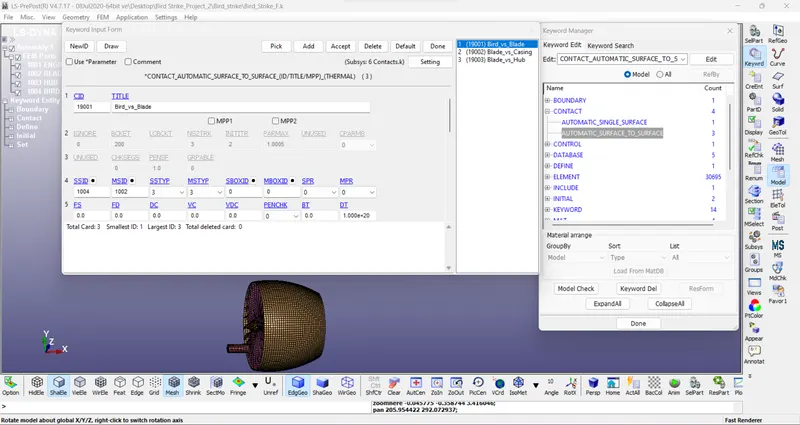
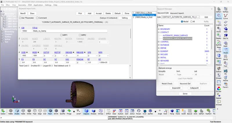
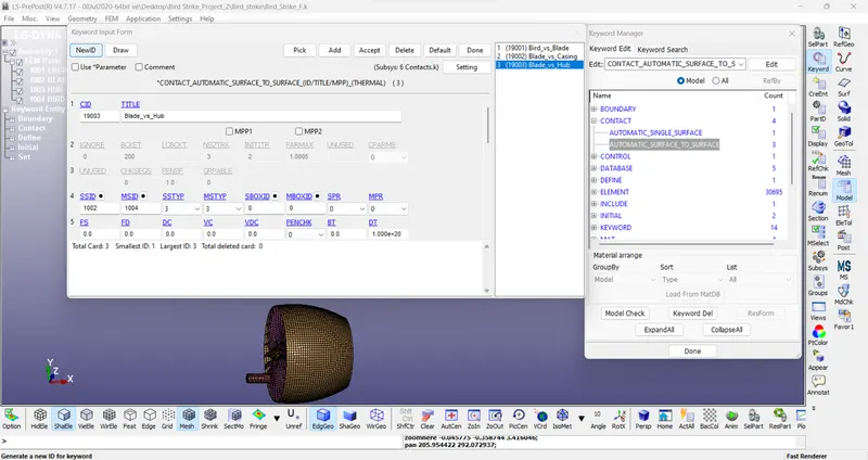
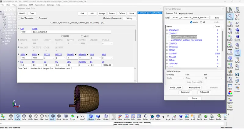
In this model, the contact card is required to identify contact between parts. Here 4 contacts are generated,
- contact between Blade & Bird // Blade & Hub // Blade & Casing.
- contact for blade self-penetration.
- Contact between Blade & Bird // Blade & Hub // Blade & Casing:
AUTOMATIC_SURFACE_TO_SURFACE contact card is defined for the contact between the bird and blade where blade is treated as master and the bird as slave part.
- Contact for blade self-penetration:
AUTOMATIC_SINGLE_SURFACE card is defined for this contact in order to prevent penetration.
8) Control cards -
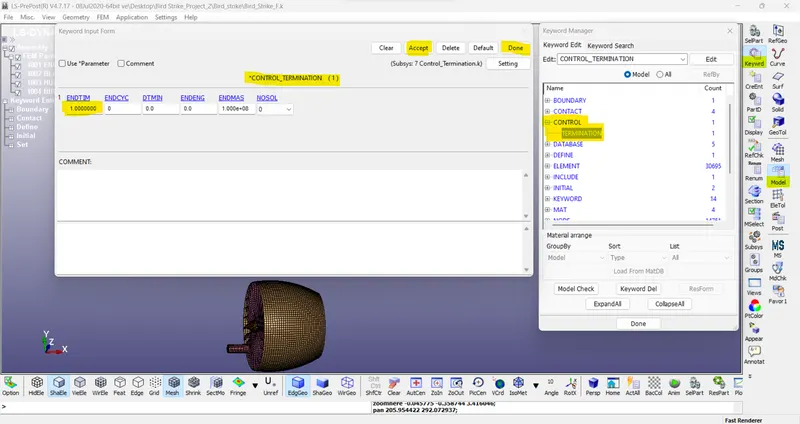
- i) Termination:
For that go to Model and Part > Keyword Manager> All > Control > Termination. Provide the End time is 1ms.
9) Binary_D3plot and ASCII option -
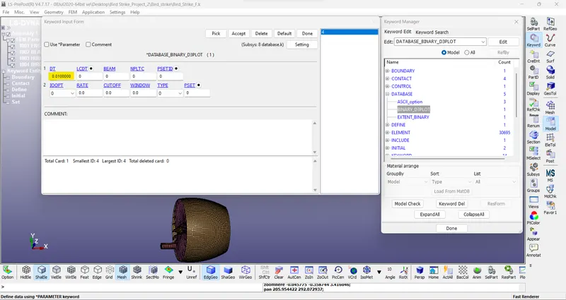
- i) BinaryD3plot:
Here provide DT value is 0.01ms.
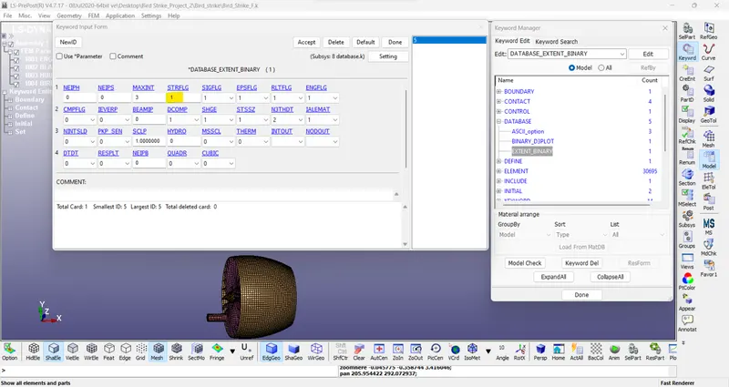
- ii) Extent Binary:
This keyword is useful for strain tensor data. (STRFLG=1)
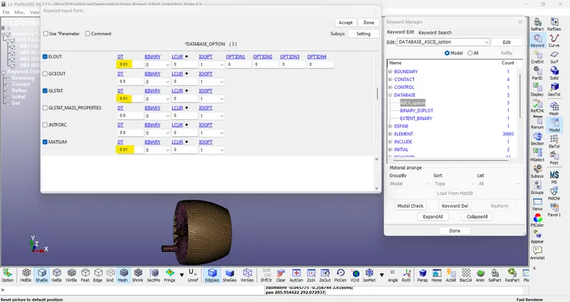
- iii) ASCII options:
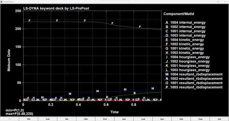
Here we use ELOUT, GLSTAT and MATSUM.
10) Include -
One of the main goals is to develop an understanding of the INCLUDE keyword so that we can work with multiple files simultaneously and use them for our simulation so a separate keyword file is generated for each part and included in one keyword file named as the main ‘.k’ file.
11) Model check -
After assigning all the keywords check the model using the model checker and check if it shows any warning or not. If it shows any type of error then remove it. After that save the file as a ".k" format. Run the file in the LS-RUN solver and if it ends as a normal termination then the model is correct.
// Results -->
12) Simulation (d3plot) -
Effective Plastic strain ->
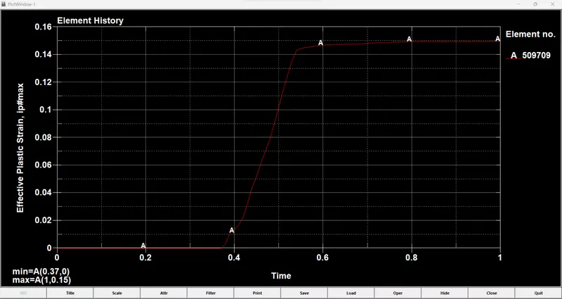
/The maximum Effective Plastic strain is 0.1495.

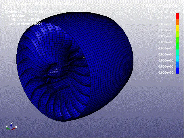
Von mises Stress ->
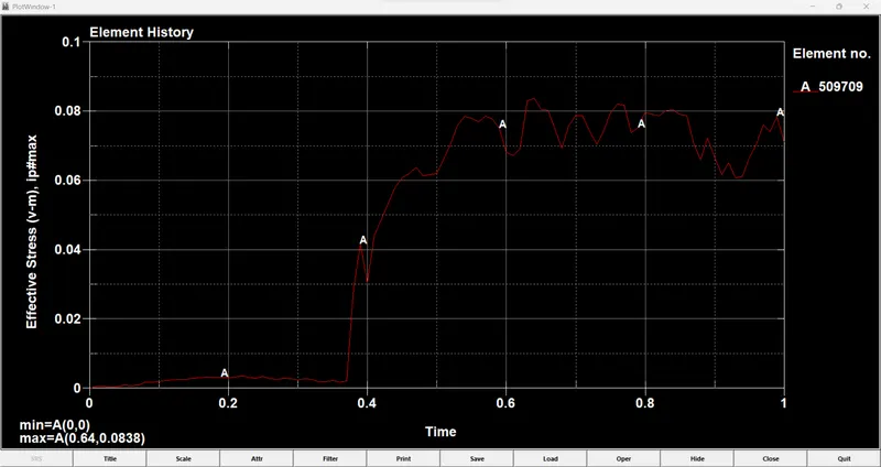
/Maximum Von mises stress as 0.1886 GPa.
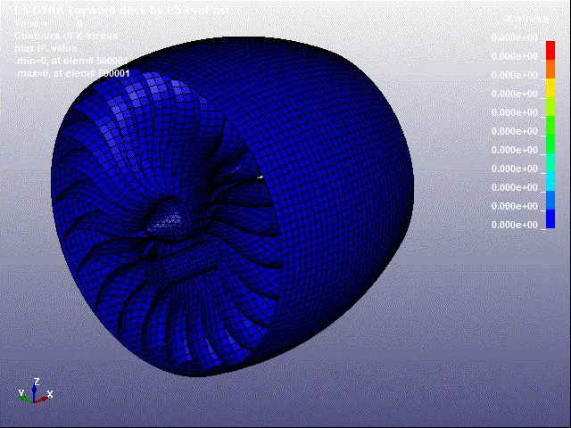
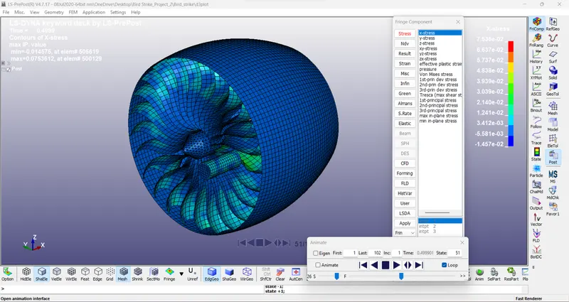
X-Stress ->
/Maximum X Stress as 0.07536 GPa.
13) Post-Processing -
/a1. Energies Plot (glstat) ->
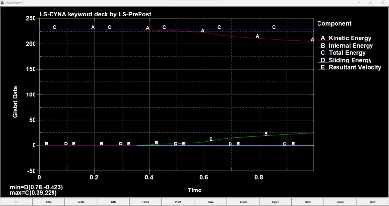
As we can see the point at which the bird hits the blades, its kinetic energy reduces and internal energy increases and also the total energy remains constant throughout which prove the fact that energy cannot be created or destroyed, it can only be converted into one form to another.
/a2. Matsum plots ->
/b. Stress Plot –>
/c. Strain Plot –>
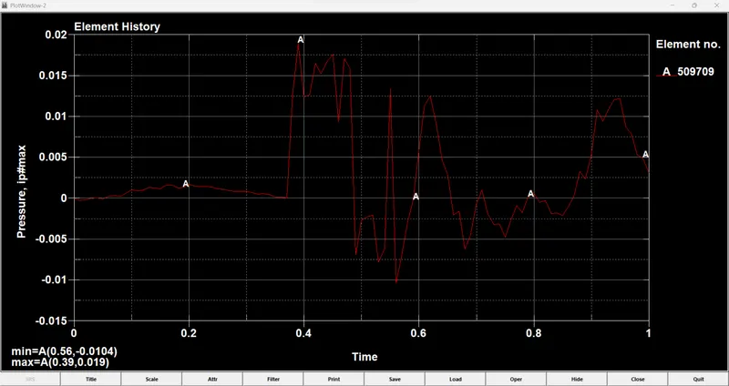
/d. Pressure Plot –>
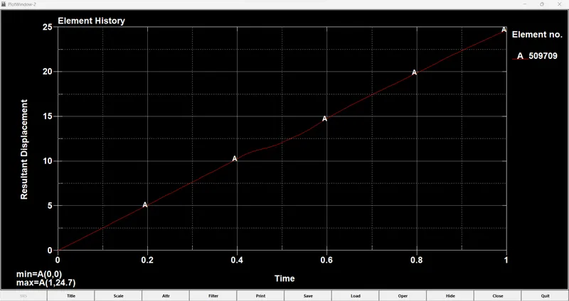
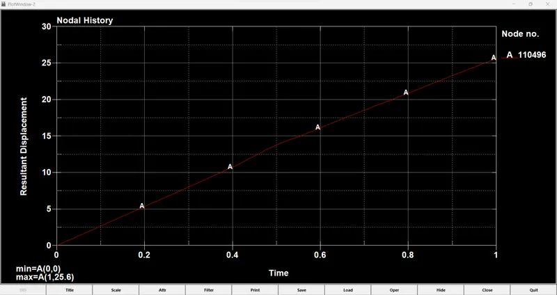
/e. Resultant Displacement Plot –>
CONCLUSIONS:
-The keyword file to simulate a bird strike on an Aero Engine is created by following the necessary conditions and requirements.
-In the simulation, the blades at the impact zone are damaged.
-Mass scaling approach can not be adopted because of the small run time to reduce the runtime with the optimum value of DT2MS because of small run time.
-The initial keyword files were debugged to get a realistic simulation of the bird strike phenomenon.
-Learned to create and organize as well as debug the input keyword files similar to a professional setting when dealing with large models and multiple people working with the same model simultaneously.
# Final Simulated Model database link -->
https://drive.google.com/drive/folders/1AGcDP_4ozBYXK_3Wq-B_uTtziUgCTiDS?usp=sharing
https://drive.google.com/drive/folders/1C8KLzYgAZ0NCl5fsFMb3i9m47PiVyzO6?usp=sharing