Bird Strike - Project - 2
Aim : To create the simulation of bird strike on the Aero Engine from the given FE model.
Requirements for this project :
-
The blades should rotate at a constant velocity but the casing should remain stationary.
-
The cylindrical bird model should travel along its own axis and hit the blades.
-
Use elastic material for the bird(2000MPa) and the casing(200GPa). The material model for the blades is attached. The velocity of the engine blades and the birds can be chosen so that blade failure can be seen within a short span of time.
-
Follow a consistent numbering approach 100000+ for nodes, 500000+ for elements, and 1000+ for the parts. All other keywords should be numbered within 10000-19999 while following a range for each one. This guideline that the student is following should be included in the final submission.
-
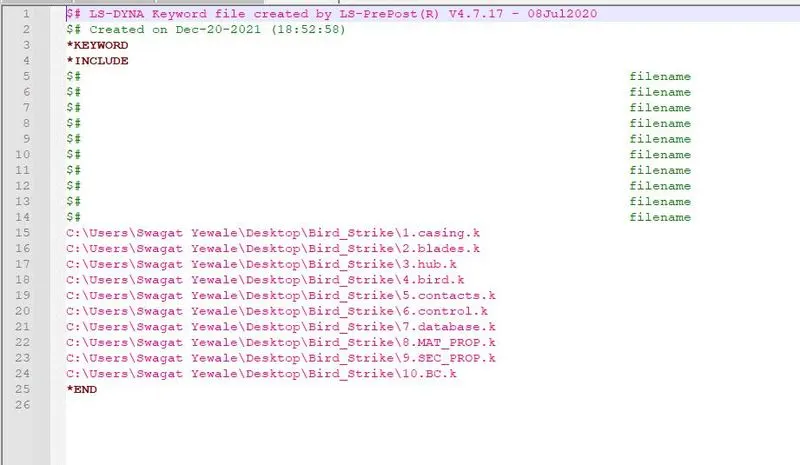
The bird, casing, and the blades should be in different input files and there should be one main file referencing all the input files. The main file should contain only references. Control cards and boundary conditions should be there in another separate file. The reference includes path should be such that the folder can be copied anywhere and it is able to correctly reference all the files and run the simulation.
-
These two requirements are a must in a professional setting when dealing with large models and multiple people working with the same model simultaneously.
- Units used here (kg, mm, ms, kN, Gpa, KN-mm)
- Density in kg/mm^3, Youngs modulus in Gpa, Sigy in Gpa
Methodology :
- The FE model consists of four parts that need to be separated and save partwise. The suitable material is created and saved in a sub-folder.
- The node number, element number, and part number are assigned as mentioned above. Also, to conclude the final simulation create the main file with the *include file and run the explicit simulation using mass scaling.
Procedure :
1. Import the keyword file
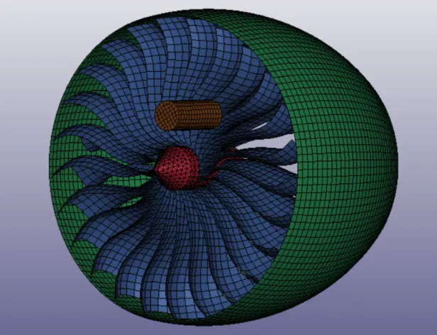
2. Create new keyword files for each component.
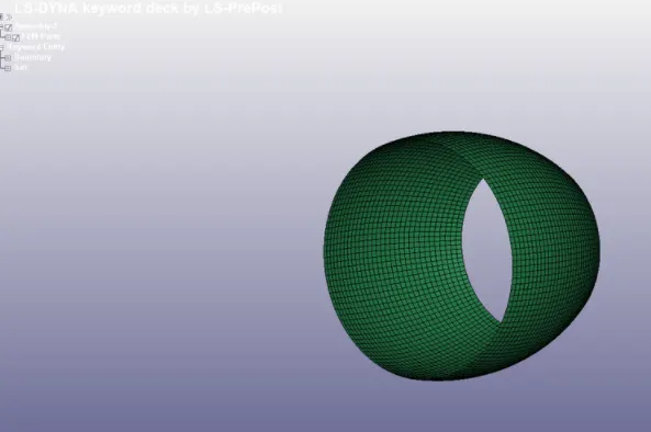
- Engine Casing :
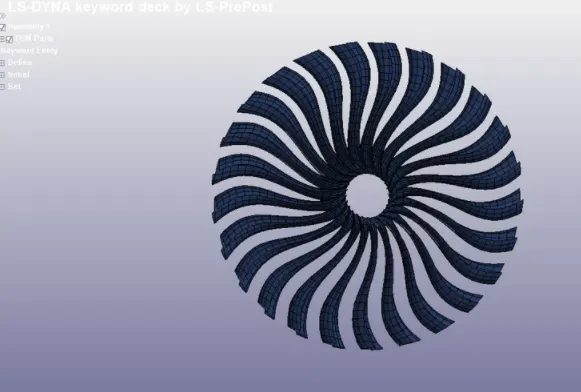
- Blade :
- Hub :
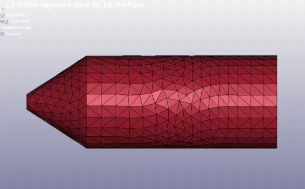
- Bird :
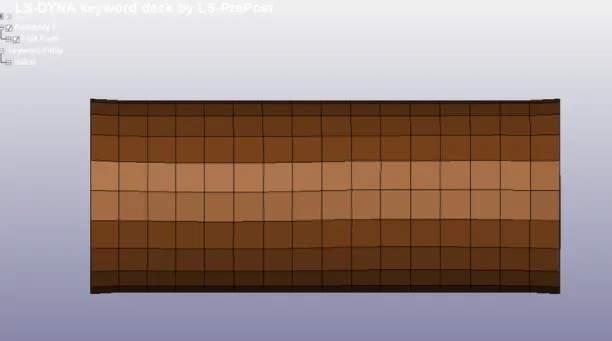
3. Create the material and section for each component.
Material :
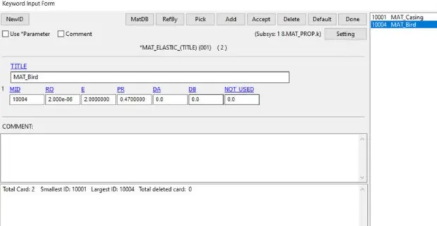
1. Bird :
- *MAT_ELASTIC card material is selected and properties are assigned from the journal "https://www.researchgate.net/publication/258630404_BirdStrike_Modeling_Based_on_the_Lagrangian_Formulation_Using_LS-DYNA".
- The given properties are, Density-2.000 , Young's Modulus-2.000, Poisson Ratio-0.4700 e −6.
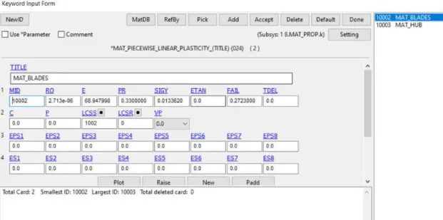
2. Blades :
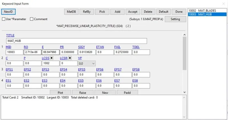
- *MAT_24_Piecewise_Linear_plasticity card is given with properties of Aluminium, Density-2.713 , Young's Modulus-68.946999, Poisson Ratio-0.3300, Yield stress-0.0133600, Failure flag-0.2723, and Tangent modulus is given as Load curve ID by plastic strain rate behaviour.
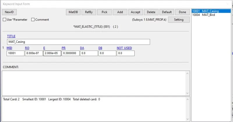
3. Casing :
- *MAT_ELASTIC card material is selected nd the steel properties are assigned Density-7.8000 , Young's Modulus-210, Poisson Ratio-0.3300 e-6.
4. Hub :
- *MAT_24_Piecewise_Linear_plasticity card material is selected and the steel properties are assigned Density-8.2000 , Young's Modulus-145, Poisson Ratio-0.30, Yield stress-0.81000, Tangent Modulus-70.000, Failure flag- (Default)
Section :
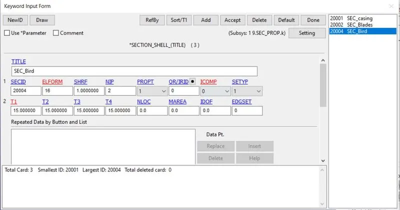
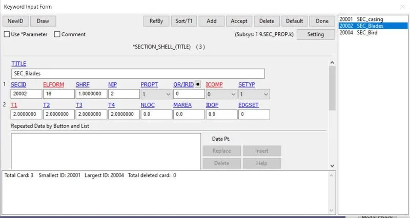
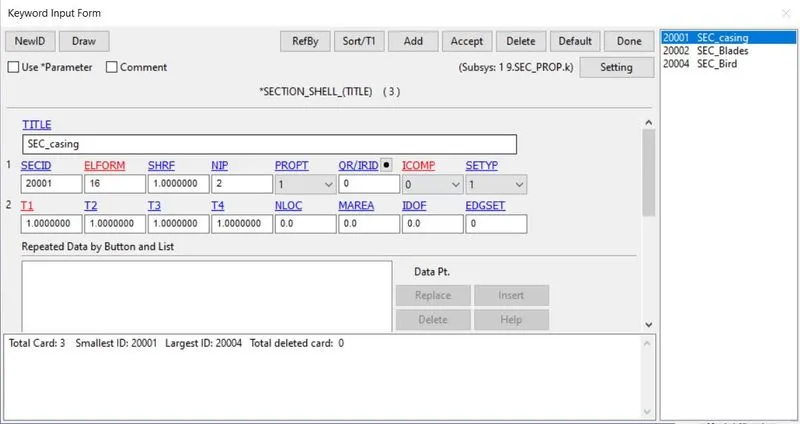
Section card is created individually upon the following FE models i.e., bird, blade, and engine casing with Element formulation of 16 (Fully integrated shell element modified for higher accuracy)
- Bird :
The thickness is assigned to be 15mm
- Blades :
The thickness is assigned to be 2 mm
- Casing :
The thickness is assigned to be 1 mm
- Hub :
The Element formulation is assigned to be 10 (point tetrahedron)
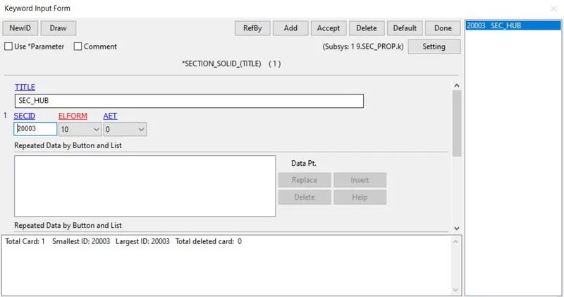
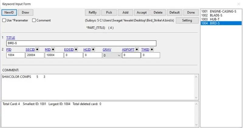
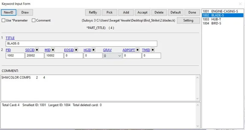
4. Assign the part with respect to the material cards and section with proper Subsys.k after inserting the FE parts into a single model file
- Bird :
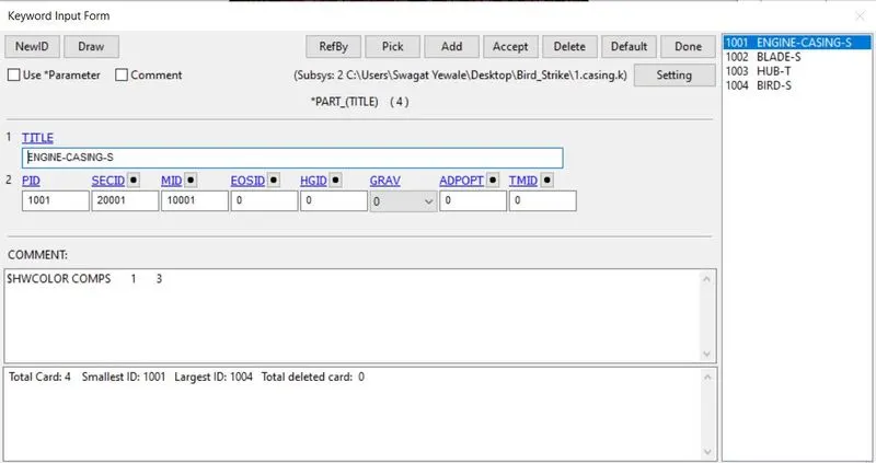
- Blades :
- Casing :
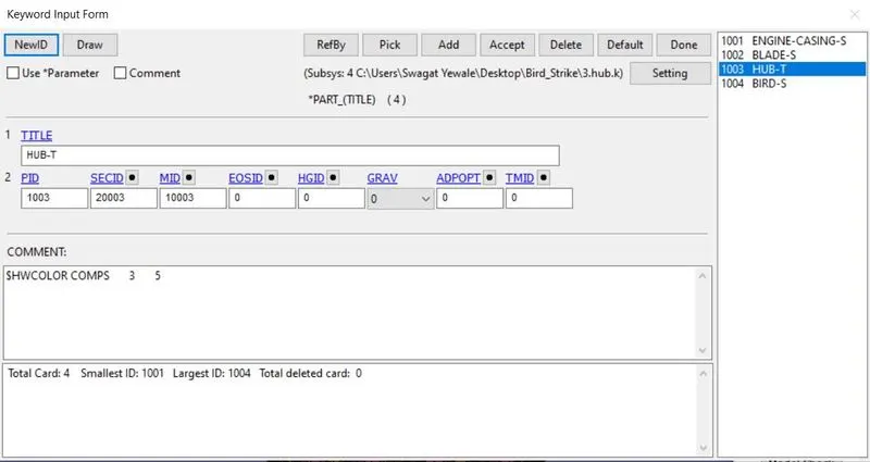
- Hub :
5. Create Contact
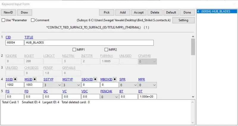
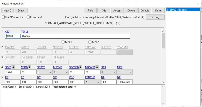
- Contacts are created using Part ID type, SSTYPE=3 & MSTYP=3
- Hence the blades should rotate according to the hub, *CONTACT_TIED_SURFACE_TO_SURFACE is used to tied the surfaces with the blade as a slave and hub as master
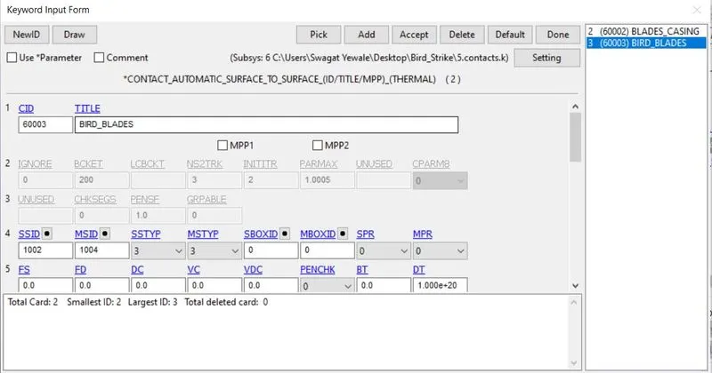
- Contacts are created using Part ID type, SSTYPE=3 & MSTYP=3
- In order for the bird needs to hit the blade *CONTACT_AUTOMATIC_SURFACE_TO_SURFACE is used as the bird as a slave and blade as a master
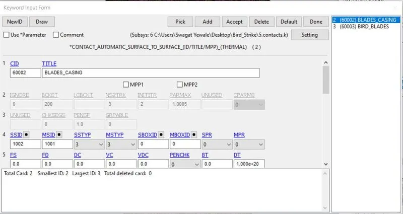
- Contacts are created using Part ID type, SSTYPE=3 & MSTYP=3
- Up-next, the blade should not suppose to penetrate the casing. Again *CONTACT_AUTOMATIC_SURFACE_TO_SURFACE is used as the blade to be slave and casing as a master
- Here for the single contact, we used Part ID type, SSTYPE=3 & MSTYP=0
- Eventually, once the bird hits the blades the deformed blades not supposed to penetrate with each other. Here *CONTACT_AUTOMATIC_SINGLE_SURFACE is used
6. Boundary Condition
SPC
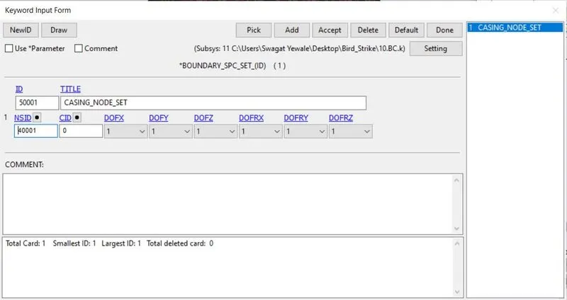
- Though the turbine engine case supposed to be fixed at the airplane wing.
- It has to be constrained in all the directions i.e, Translation and Rotation Initial Velocity
Initial Velocity
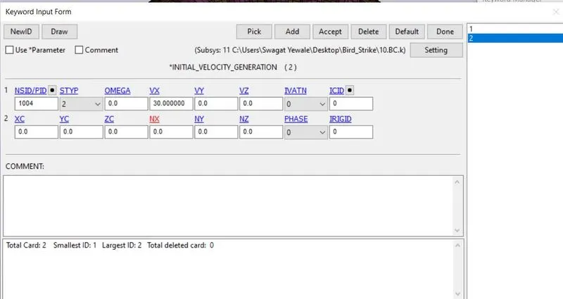
- The average velocity of the bird travels from the references is observed to be approximately 20 to 80 mm/ms
- Here the velocity of the bird is assigned to be VX=30 mm/ms along the X-axis translative direction
Angular velocity
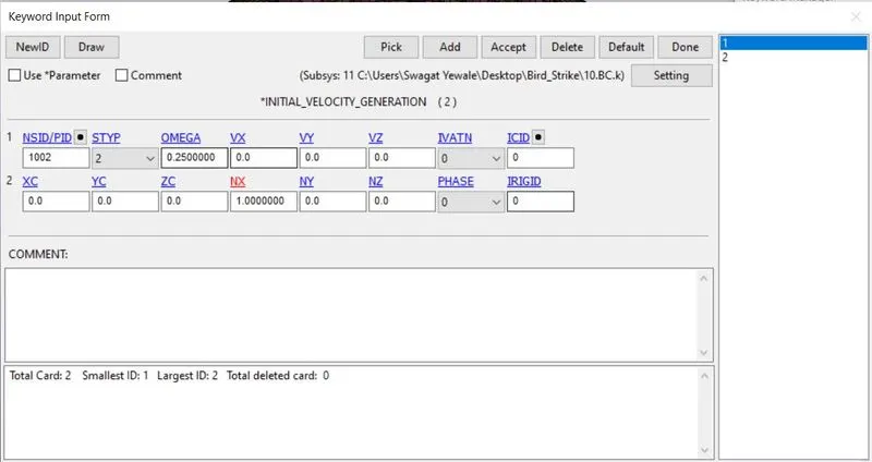
- The angular velocity of the blades is roughly around an average speed of around 3000 to 20000 RPM Considering 5000 rpm and convert it to radiant.
- From which angular velocity OMEGA=0.25 rad/ms, NX=1 (x-direction cosine)
7. Control
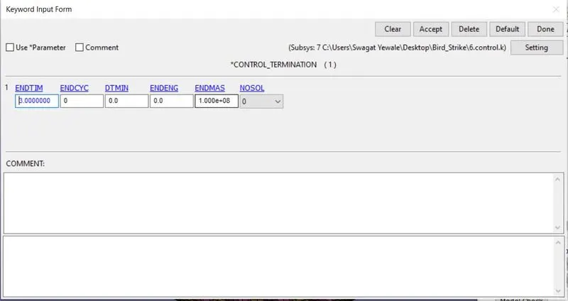
Termination time setup is 3 ms
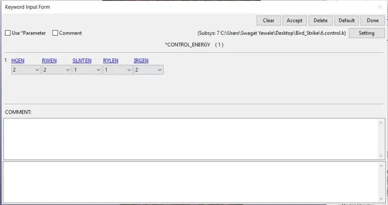
Energy card to take into account hourglass energy with hgen=2 (as shown below)
Control Timestep card plays important role in reducing the runtime. We can have different combination of DT2MS and TSSFAC check the estimated runtime and percentage mass added during mass scaling. Here we will try to keep the percentage of mass added below 7% and reduce the runtime.
- 1st trial we done by keeping DT2MS = -6.0E-05 and TSSFAC=0.9 the runtime estimated is 15hrs 26 min but actual it took 135 min with 0% mass addition.
- 2nd trial we done by keeping DT2MS = -6.0E-04 and TSSFAC=0.9 the runtime estimated is 40 min but actual it took 3 min with 24.6% mass addition.
- 3rd trial we done by keeping DT2MS = -4.0E-04 and TSSFAC=0.9 the runtime estimated is 1hrs 32 min but actual it took 5.6 min with 6.6% mass addition.(Acceptable)
8. Database
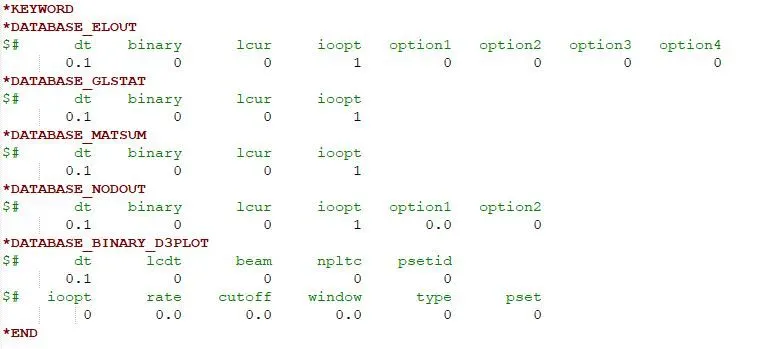
Generally, the list of output request is specified with the Time interval between outputs DT= 0.05 ms for GLSTAT, MATSUM, NODOUT The frequency of the animation file is set to be Time interval between outputs DT= 0.10 ms
9. Renumber
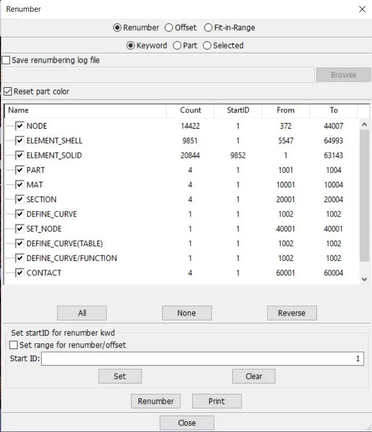
Individual saved files are now opened and with help of Renumber option available one by one node, element, the part can be renumbered as per the given standard
10. Include
- Include all the card into the main file and run the solver after saving it
- The final.k file will include all the file i.e components, material, section, part, boundary condition, contact, control, and database( As shown below)
Results :
Energy plots :
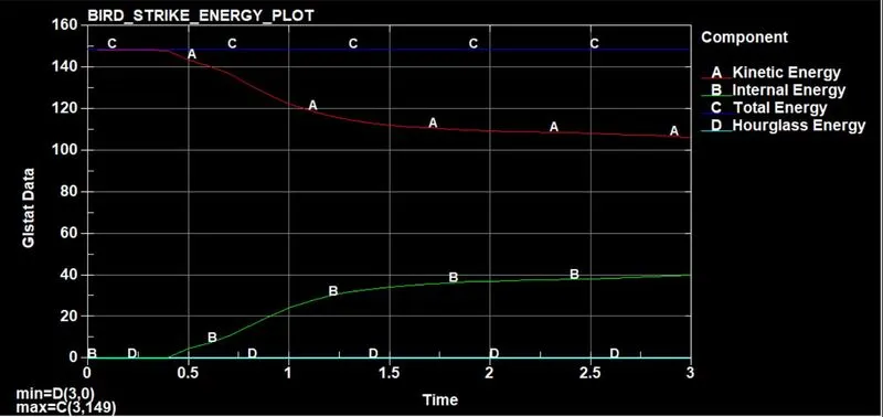
- From the energy plot we can see the Total energy is almost constant over the period of simulation which indicates the result simulation run well.
- This is the 1st check to validate the accuracy of the simulation done.
- Hourglass energy is zero through out the simulation.
- The kinetic energy and internal energy shows a very similar pattern during the simulation where K.E reduces and I.E increases after the impact.
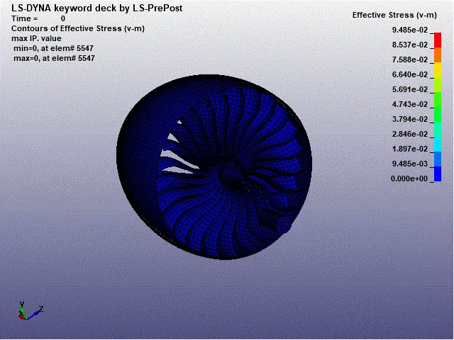
Von-mises stress plot :
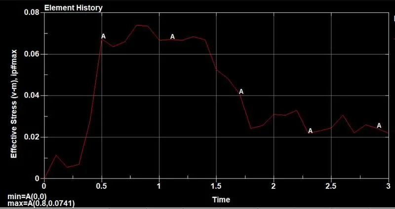
- This stress plot is taken on one of the element of the blade where the impact 1st incidents.
- At nearly 0.5 ms the stress peaks and reaches a value of 0.0741 Gpa just at the moment of impact then reduces and stays at a value of 0.0215 Gpa throughout the simulation.
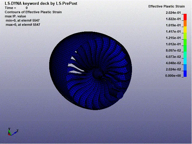
Plastic strain plot :
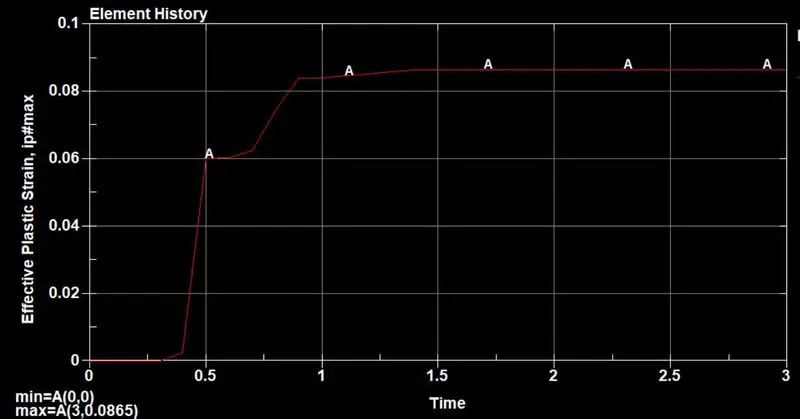
- This strain plot is taken on one of the element of the blade where the impact 1st incidents.
- At t= 0.5ms the strain values peaks to 0.0865 i.e. 8.65% strain then is constant throughout the simulation.
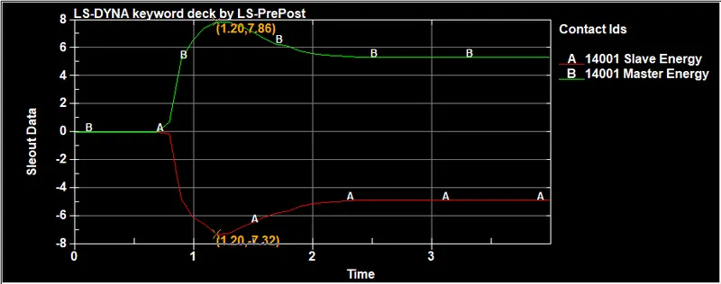
Contact Plot : Blade-Bird contact
Von- Mises Stress :
Effective plastic Strain :
Conclusion :
- All the components are following a consistent number pattern for each element, node, and part as followed in many Industries.
- All the files such as for component, BC's, contact, control, database are included in the Main file.
- The Boundary Conditions and load conditions are mimic the real-world scenario.
- For Mass-scaling, the percentage of mass added is 6.67% which below 7%, and accepted. From the energy plot, we can observe that total energy is constant over the simulation which represents the simulation runs well (1st check).
- The max Von-Mises stress produced in the fan blade is 0.09485 Gpa at nearly 0.5ms of simulation The max strain developed is 0.2024 at 0.5 ms of simulation and remains constant over the simulation