bike crank problem
- Problem statement
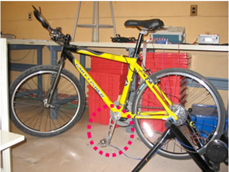
Consider a crank mounted on a bicycle as illustrated in the picture below. When a rider is pedaling the bicycle, she or he is applying a variable force to this bike crank. To simplify the analysis, we'll neglect the variation of the force with time and focus on the response of the crank to a static force. This is analogous to taking a video of the bike crank and analyzing a single frame by itself.
In this module, we will work with the following crank model. The geometry will be provided to you as a download. The crank is made of aluminum 6061-T6 alloy. For this material, the Young's modulus is 1x10⁷ psi and the Poisson's Ratio is 0.33.
Using ANSYS Mechanical, we will calculate the following:
- Deformed shape and displacement field
- Stress distribution in the crank
1. Pre-processing
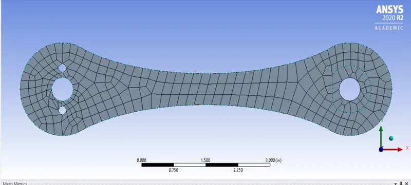
mesh : Nodes 6418 Elements 1139
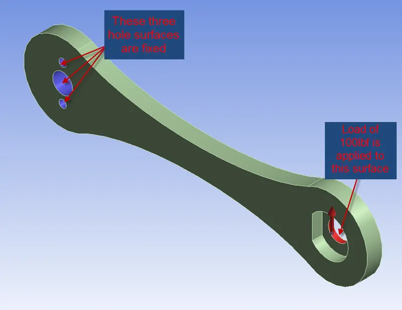
boundary conditions
Solving
Results
a) Total deformation
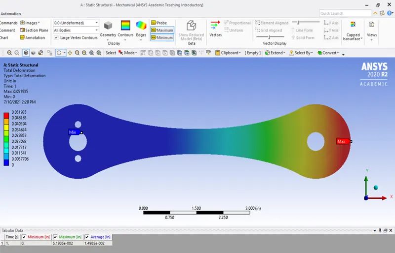
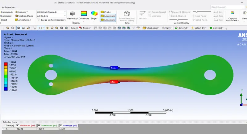
b) Normal stress in X direction
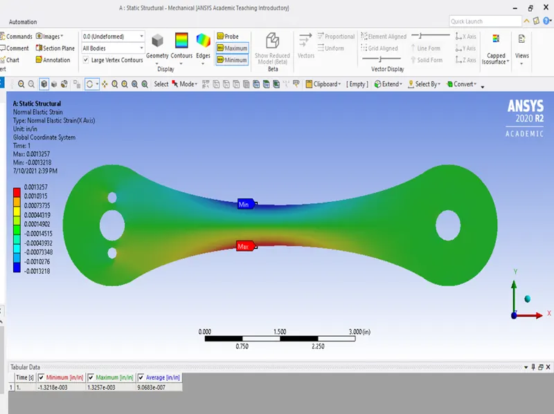
c) Strain in X-direction
Verification and validation
a) Hand calculations
| Parameters | Hand calculations | stress (ansys) |
| Maximum stress(Psi) | 14300 | 13300 |
| Deformation(Inch) | 0.02 to 0.05 | 0.05 |
b)Experiment using digital image correlation at data points lab
The experiment was conducted on the same specimen at Coronnel University and the strain was calculates using digital image correlation
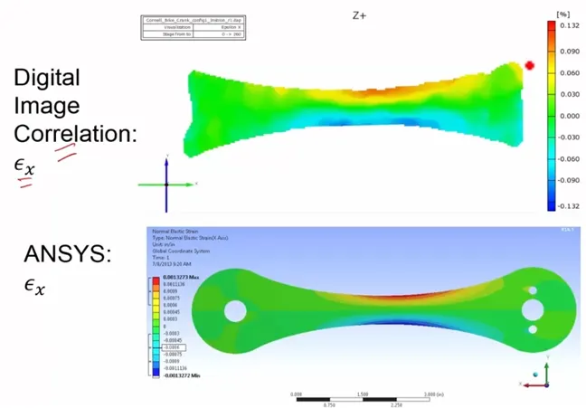
Thus data is validated from experiments .