Batchmeshing of Hood and Fender component in Hypermesh
Objective:
The objective of this project is to perform the batchmeshing of the given 'Hood' and 'Fender' components of a car in Hypermesh, based on the given quality criteria and analyze the mesh to understand the pros and cons of batchmeshing. Also, assign the non-linear material property Steel to them using the Radioss profile.
The following quality criteria need to be followed,
| S.N | Quality Criteria | Value |
| 1 | Aspect Ratio | 5 |
| 2 | Skewness | 45 |
| 3 | Warping | 15 |
| 4 | Taper | 0.5 |
| 5 | Min. Length | 2mm |
| 6 | Max. Length | 8mm |
| 7 | Min angle Quad | 45 |
| 8 | Max angle Quad | 135 |
| 9 | Min angle Tria | 20 |
| 10 | Max angle Tria | 120 |
| 11 | Tria % | 10 |
| 12 | Target element size | 5mm |
Procedure:
Batchmeshing is a fully automated process to perform 2D meshing of thin components where the software itself performs all the three processes of pre-processing i.e. geometry cleanup, midsurface extraction, and meshing. It is a fast method to perform the 2D shell meshing compared to manual meshing. To perform the batchmeshing, the user needs to provide a parameter file based on which Hypermesh will perform the geometry cleanup on the component and extract the midsurfaces, and criteria file based on which Hypermesh will mesh the extracted midsurfaces. In Hypermesh, batchmeshing tool is available in the 2D>automesh tool panel.
Model 1:
The first model given is an assembly of Hood components of a car. The first step is to import the geometry into the Hypermesh workspace. Then all the solids are deleted, if any, as we don't need solids to perform the 2D meshing. This model consists of a total of five individual components as shown below.
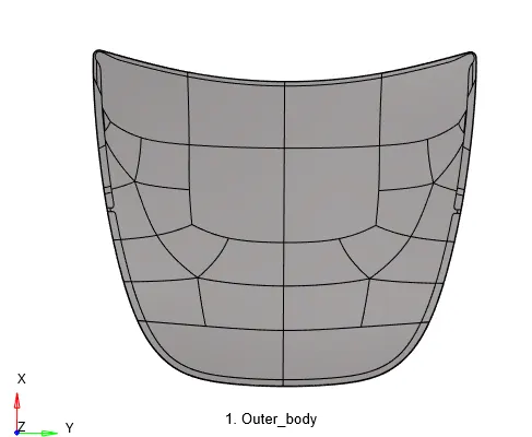
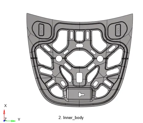
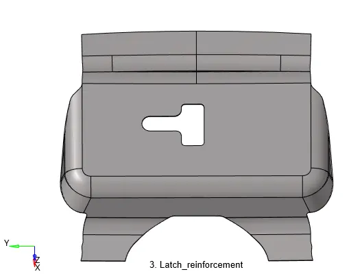
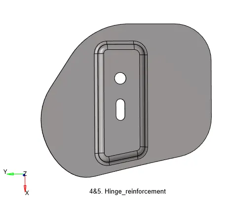
To perform the batchmesh, we need a parameter file and a criteria file. The parameter file can be created by going to Preferences>Parameters file settings. For our purpose, we are going to use the default parameter file 'crash_5mm.param' available in the Hypermesh software directory. Similarly, the criteria file is created by going to Preferences>Criteria File Settings. The given quality parameters are entered and the file is saved, named as 'batchmesh.criteria'.
To perform the batchmesh, go to 2D>automesh>batchmesh/QI optiomize>batchmesh. In the tool panel, the respective parameter and criteria files are selected and all the surfaces of all the components are selected at once. On hitting the mesh button, Hypermesh will perform the geometry cleanup, midsurface extraction, and 2D meshing of the extracted midsurfaces.
On analyzing the mesh, we can observe that feature capturing is not proper at some places as shown in the image below for the hemming portion.
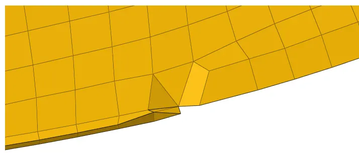
Also, there are a lot of back-to-back trias which is not good. Next, element quality is checked using the qualityindex tool. The image below shows the quality results for all the five components combined.
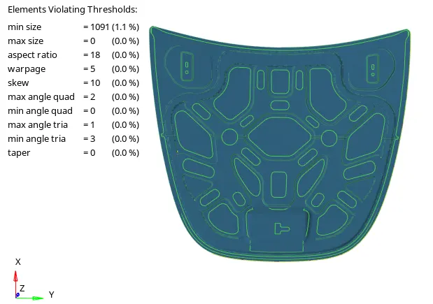
We can observe that there are a lot of elements failing for the quality criteria and needs additional cleanup or remeshing. Also, there are a lot of trias present. For all five components combined, there are 1238 (3.1%) trias. On the other hand, when the whole process was done manually, we were able to achieve zero element failure with just 620 (0.66%) trias.
Model 2:
The second given model is a 'Fender', consisting of one single component, shown below.
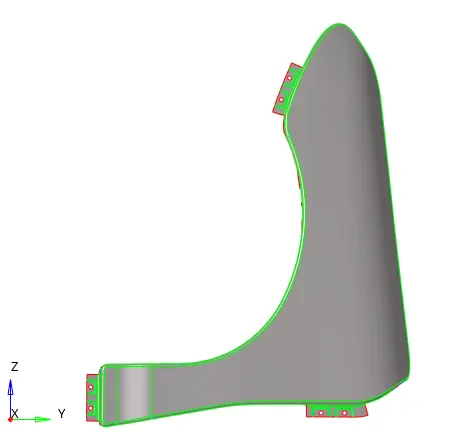
Similarly, batchmeshing is performed for this component using the same parameter and criteria file. And, the following mesh is generated.
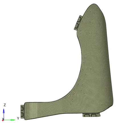
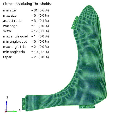
Again, we can observe that there are a lot of elements failing. This time feature capturing is fine. But still, there are a lot of back to back trias.
Assigning non-linear material property:
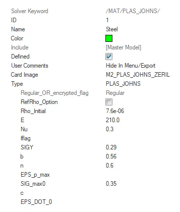
Finally, the non-linear material property 'Steel' is assigned to all the components. First, make sure we are in the Radioss user profile. Then to create the non-linear property, right-click>create>material and name it as 'Steel'. Under the material parameters, configure the card image to M2_PLAS_JOHNS_ZERIL. This card is used for non-linear property. Next, we need to enter the material parameters. The image below shows the material created with the values.
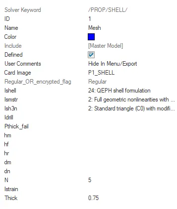
Similarly, a property is created by right-click>create>property. The image below shows the property created with the configured values.
Then, both material and property are assigned to the mesh component by right click>assign on the component in the model browser. The same procedure is repeated for all the components.
Conclusion:
Batchmeshing of all the components was successfully done. Based on the mesh results, we can conclude that this method is good only if the mesh is required quickly, and if the geometry is not too complex. The mesh results depend a lot on the parameter and criteria file configuration. Also, the elements were failing for quality criteria. This means, even after batchmeshing, some manual re-meshing is required to eliminate all the errors.
Finally, non-linear material property was created for all the components.