AutoCAD_Drafting images by Coordinate System Methods_Week 1
1.
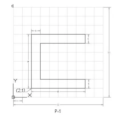
- AIM: To Create the geometries using Line tool or circle tool wherever required from P1 to P10 using the coordinates system method in AutoCad.
- PROCEDURE: The step by step procedure for each picture (P1, P2, ....P10) is given below:
STEP 1: On opening the AutoCad software, setup the units to Imperial template and decimal system to 0.000 .
STEP 2: Set the limits in the command tab using "LIM" before drafting.
STEP 3: Once the limits are set, using Line tool, specify the first point (2,1).
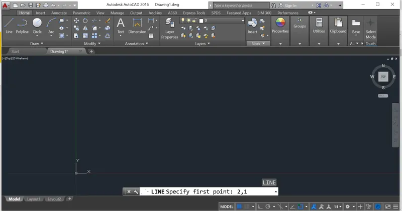
STEP 4: Now the dimension in the X-direction is 6 units and in the Y-direction is 0 units, so this accordingle needs to be added to the origin point (2,1). So our second point is 8,1 and this needs to be entered in the command tab.
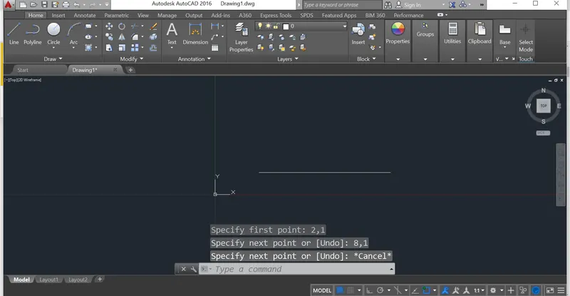
STEP 5: Now for the next step, on using Line tool, we should specify first point as 8,1. Now the dimension in the X-direction is 0 units and in the Y-direction is 1 unit, so this accordingly needs to be added to the origin point (8,1). So our second point is 8,2 and this needs to be entered in the command tab.
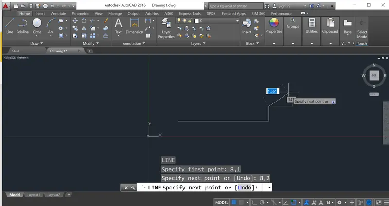
STEP 6: On continuing the line command, we need to specify the next point with respect to the first point specified in the Line command. Now the dimension in the opposite X-direction is 5 units and in the Y-direction is 1 units, so w.r.t. previous point drawn, this accordingly needs to be subtracted in x-direction and added in y-direction to the origin point (8,1). So our next point is 3,2 and this needs to be entered in the command tab.
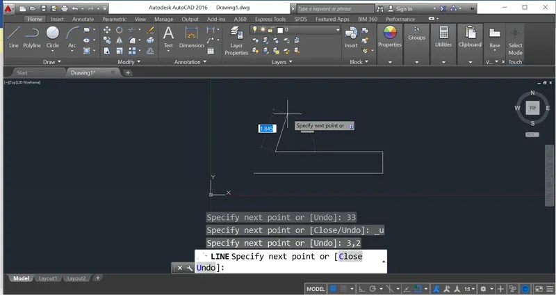
STEP 7: On continuing the line command, we need to specify the next point with respect to the first point specified in the Line command. Now the dimension in the X-direction is 0 units and in the Y-direction is 4 units, so w.r.t. previous point drawn, this accordingly needs to be added to the origin point (8,1). So our next point is 3,6 and this needs to be entered in the command tab.
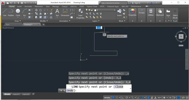
STEP 8: On continuing the line command, we need to specify the next point with respect to the first point specified in the Line command. Now the dimension in the X-direction is 0 units and in the Y-direction is 4 units, so w.r.t. previous point drawn, this accordingly needs to be added to the origin point (8,1). So our next point is 3,6 and this needs to be entered in the command tab.
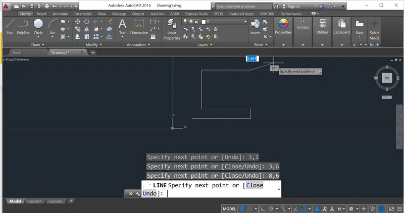
STEP 9: On continuing the line command, we need to specify the next point with respect to the first point specified in the Line command. Now the dimension in the X-direction is 0 units and in the Y-direction is 1 unit, so w.r.t. previous point drawn, this accordingly needs to be added to the origin point (8,1). So our next point is 8,7 and this needs to be entered in the command tab.
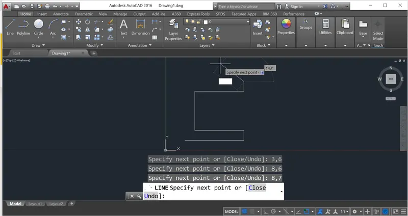
STEP 10: On continuing the line command, we need to specify the next point with respect to the first point specified in the Line command. Now the dimension in the opposite X-direction is 6 units and in the Y-direction is 0 units, so w.r.t. previous point drawn, this accordingly needs to be subtracted in x-direction and added in y-direction to the origin point (8,1). So our next point is 2,7 and this needs to be entered in the command tab
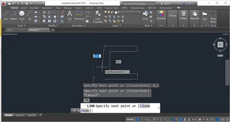
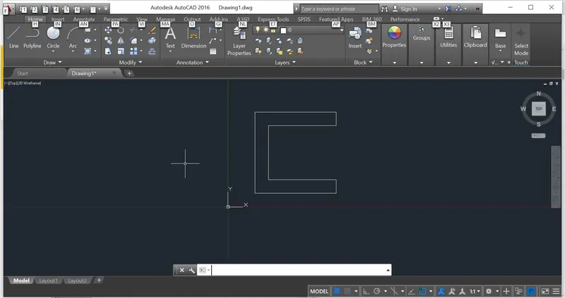
STEP 11: Now the final step is to insert the first coordinate point of the image to complete the drawing and the ESC to close the Line command.
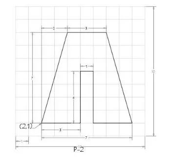
STEP 1: On opening the AutoCad software, setup the units to Imperial template and decimal system to 0.000 .
STEP 2: Set the limits in the command tab using "LIM" before drafting.
STEP 3: Once the limits are set, using Line tool, specify the first point (2,1).
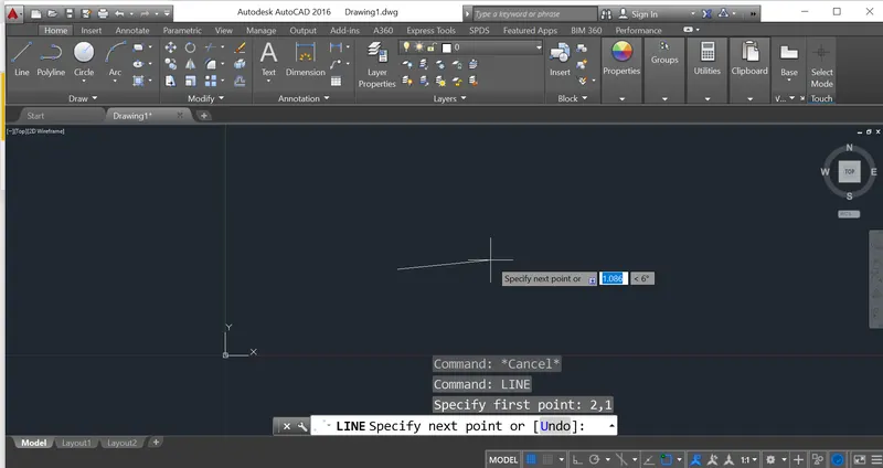
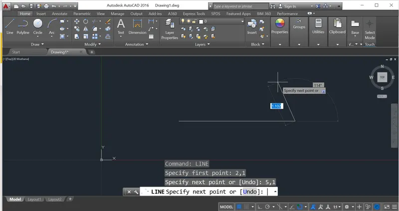
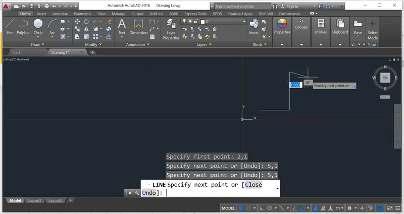
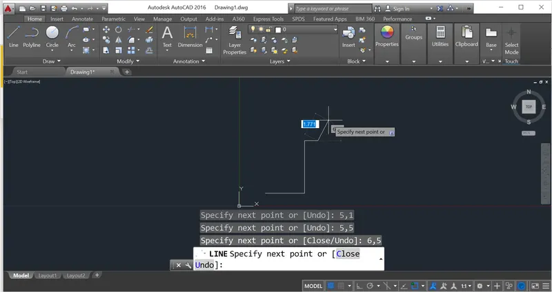
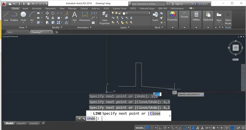
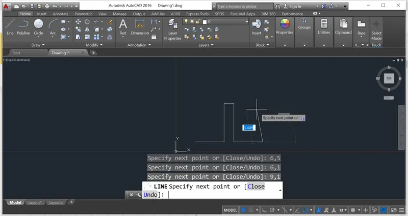
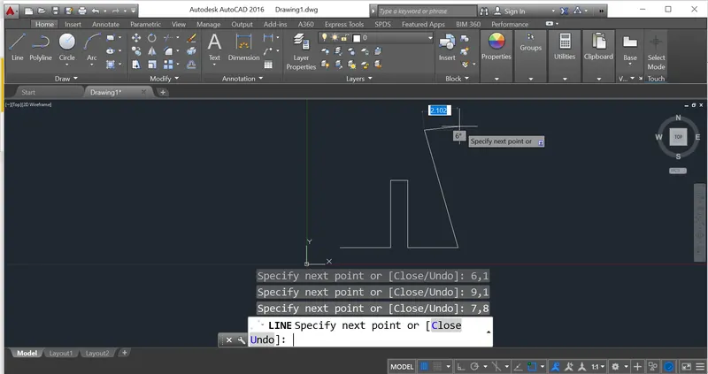
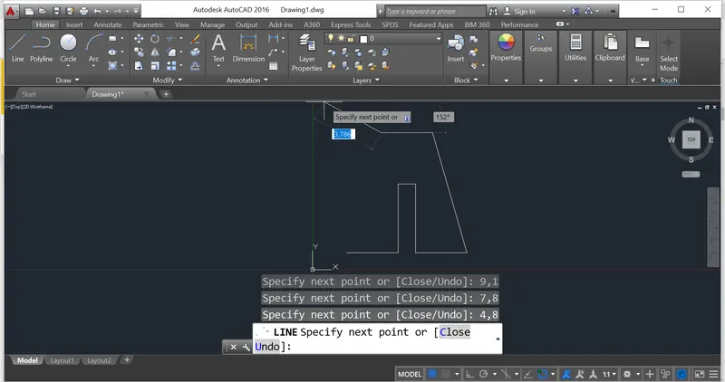
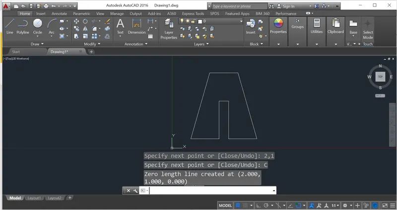
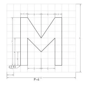
STEP 1: On opening the AutoCad software, setup the units to Imperial template and decimal system to 0.000 .
STEP 2: Set the limits in the command tab using "LIM" before drafting.
STEP 3: Once the limits are set, using Line tool, specify the first point (2,1).
STEP 4: Now the dimension in the X-direction is 1 units and in the Y-direction is 0 units, so this accordingly needs to be added to the origin point (2,1). So our next point is 3,1 and this needs to be entered in the command tab.
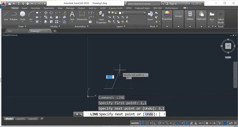
STEP 5: On continuing the line command, we need to specify the next point with respect to the first point specified in the Line command. Now the dimension in the X-direction is 0 units and in the Y-direction is 4 units, so w.r.t. previous point drawn, this accordingly needs to be added to the origin point (2,1). So our next point is 3,5 and this needs to be entered in the command tab.
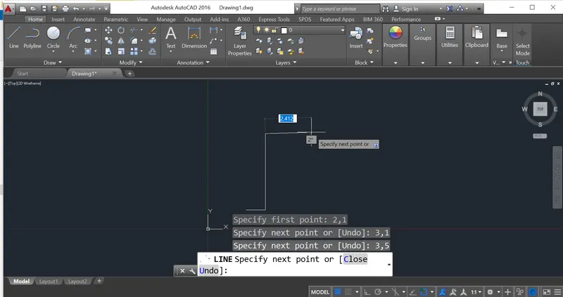
STEP 6: On continuing the line command, we need to specify the next point with respect to the first point specified in the Line command. Now the dimension in the X-direction is 2 units and in the opposite Y-direction is 2 units, so w.r.t. previous point drawn, this accordingly needs to be added to the x-direction and subtracted from the y-direction to the origin point (2,1). So our next point is 5,3 and this needs to be entered in the command tab.
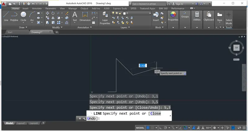
STEP 7: On continuing the line command, we need to specify the next point with respect to the first point specified in the Line command. Now the dimension in the X-direction is 2 units and in the Y-direction is 2 units, so w.r.t. previous point drawn, this accordingly needs to be added to the origin point (2,1). So our next point is 7,5 and this needs to be entered in the command tab.
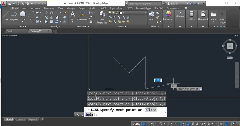
STEP 8: On continuing the line command, we need to specify the next point with respect to the first point specified in the Line command. Now the dimension in the X-direction is 0 units and in the opposite Y-direction is 4 units, so w.r.t. previous point drawn, this accordingly needs to be subtracted in y-direction and added in x-direction to the origin point (2,1). So our next point is 7,1 and this needs to be entered in the command tab.
STEP 9: On continuing the line command, we need to specify the next point with respect to the first point specified in the Line command. Now the dimension in the X-direction is 1 units and in the Y-direction is 0 unit, so w.r.t. previous point drawn, this accordingly needs to be added to the origin point (2,1). So our next point is 8,1 and this needs to be entered in the command tab.
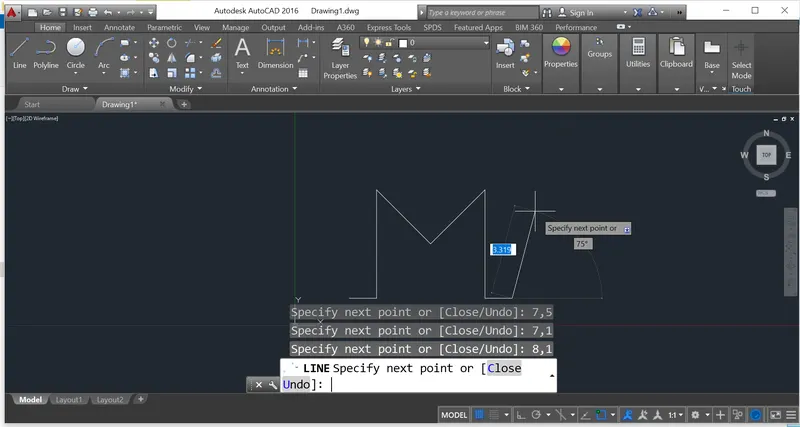
STEP 10: On continuing the line command, we need to specify the next point with respect to the first point specified in the Line command. Now the dimension in the X-direction is 0 units and in the Y-direction is 7 unit, so w.r.t. previous point drawn, this accordingly needs to be added to the origin point (2,1). So our next point is 8,8 and this needs to be entered in the command tab.
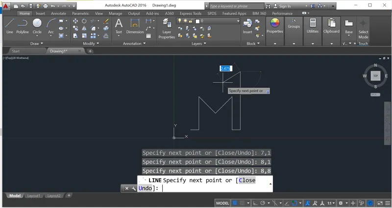
STEP 11: On continuing the line command, we need to specify the next point with respect to the first point specified in the Line command. Now the dimension in the X-direction is 1 units and in the Y-direction is 0 units, so w.r.t. previous point drawn, this accordingly needs to be subtracted in x-direction and added in y-direction to the origin point (2,1). So our next point is 7,8 and this needs to be entered in the command tab
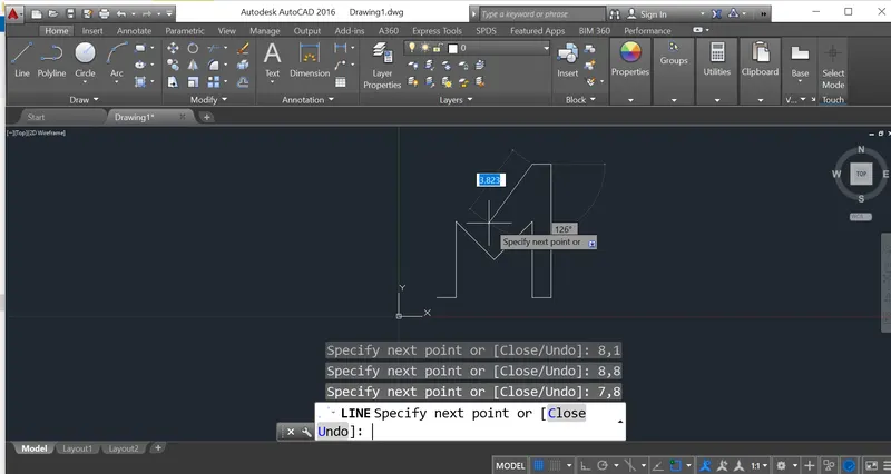
STEP 12: On continuing the line command, we need to specify the next point with respect to the first point specified in the Line command. Now the dimension in the opposite X-direction is 2 units and in the opposite Y-direction is 3 units, so w.r.t. previous point drawn, this accordingly needs to be subtracted to the origin point (2,1). So our next point is 5,5 and this needs to be entered in the command tab
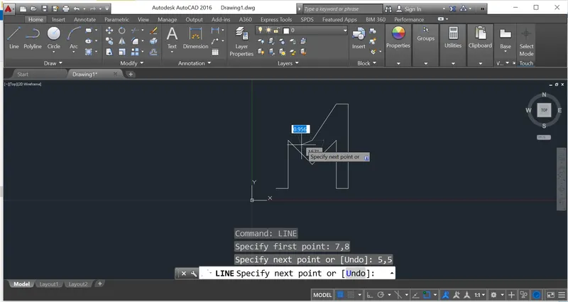
STEP 13: On continuing the line command, we need to specify the next point with respect to the first point specified in the Line command. Now the dimension in the opposite X-direction is 7 units and in the Y-direction is 3 units, so w.r.t. previous point drawn, this accordingly needs to be subtracted in x-direction and added in y-direction to the origin point (2,1). So our next point is 3,8 and this needs to be entered in the command tab
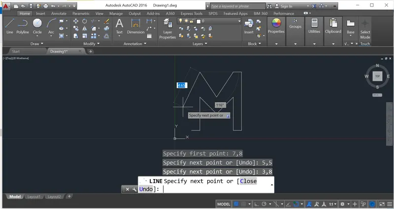
STEP 14: On continuing the line command, we need to specify the next point with respect to the first point specified in the Line command. Now the dimension in the opposite X-direction is 1 units and in the Y-direction is 0 units, so w.r.t. previous point drawn, this accordingly needs to be subtracted in x-direction and added in y-direction to the origin point (2,1). So our next point is 2,8 and this needs to be entered in the command tab
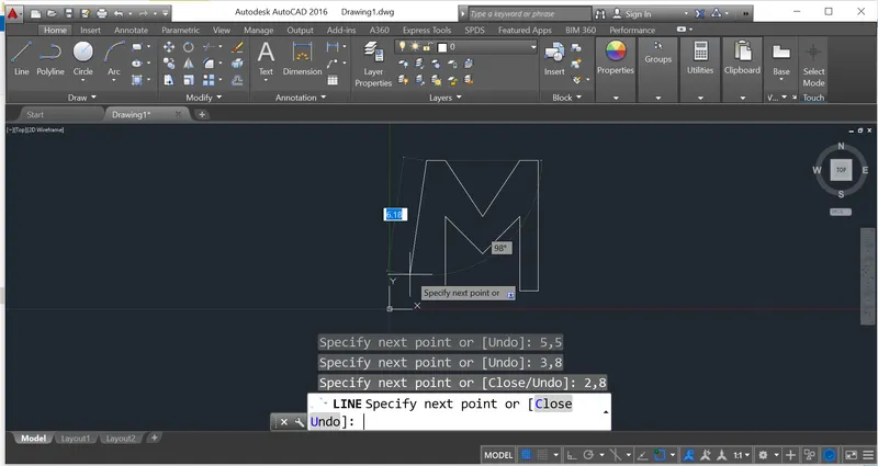
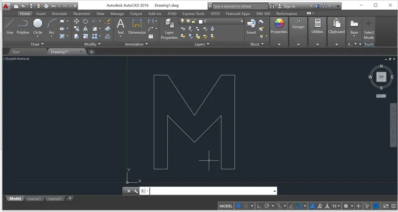
STEP 15: Now the final step is to insert the first coordinate point of the image to complete the drawing and the ESC to close the Line command.
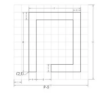
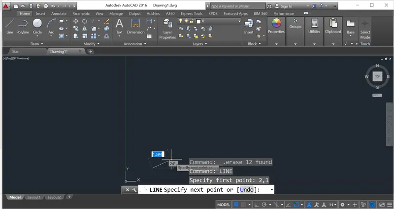
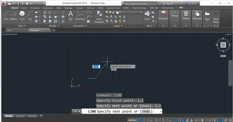
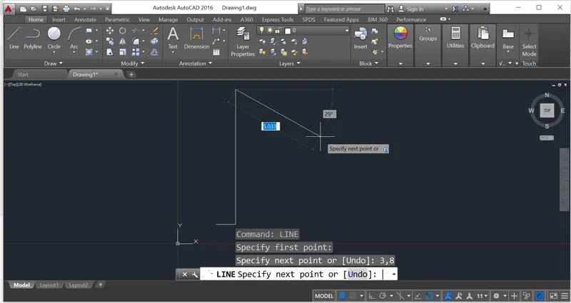
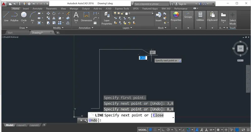
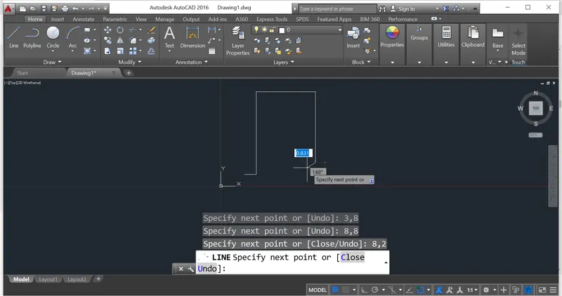
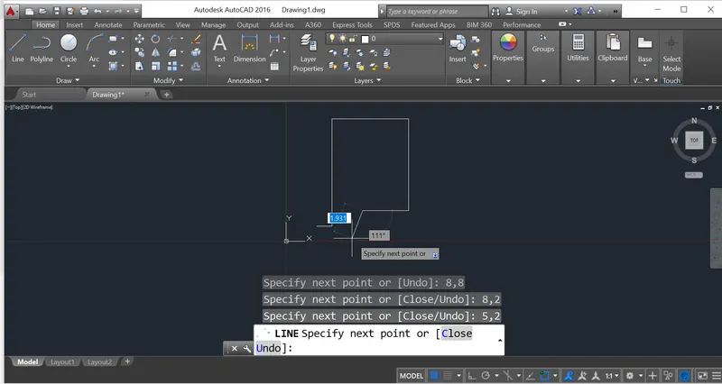
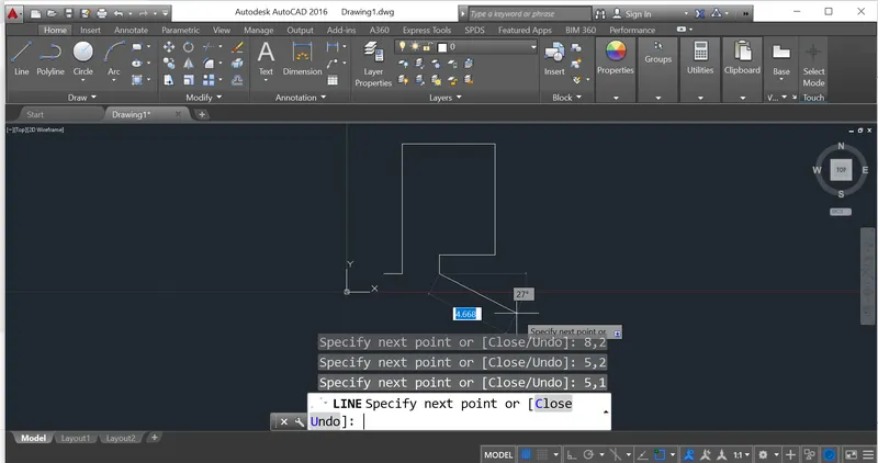
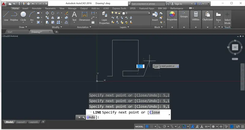
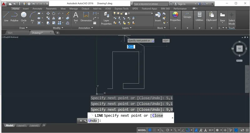
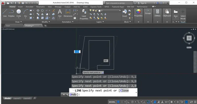
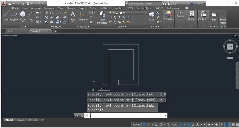
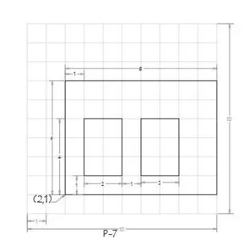
STEP 1: On opening the AutoCad software, setup the units to Imperial template and decimal system to 0.000 .
STEP 2: Set the limits in the command tab using "LIM" before drafting.
STEP 3: Once the limits are set, using Line tool, specify the first point (2,1).
STEP 4: Now the dimension in the X-direction is 8 units and in the Y-direction is 0 units, so this accordingly needs to be added to the origin point (2,1). So our next point is 10,1 and this needs to be entered in the command tab.
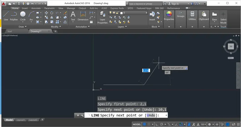
STEP 5: On continuing the line command, we need to specify the next point with respect to the first point specified in the Line command. Now the dimension in the X-direction is 0 units and in the Y-direction is 6 units, so w.r.t. previous point drawn, this accordingly needs to be added to the origin point (2,1). So our next point is 10,7 and this needs to be entered in the command tab.
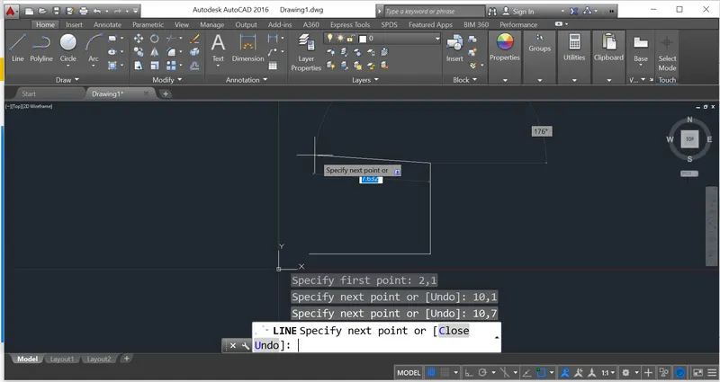
STEP 6: On continuing the line command, we need to specify the next point with respect to the first point specified in the Line command. Now the dimension in the opposite X-direction is 8 units and in the Y-direction is 0 units, so w.r.t. previous point drawn, this accordingly needs to be subtracted in the x-direction and added in the y-direction to the origin point (2,1). So our next point is 2,7 and this needs to be entered in the command tab
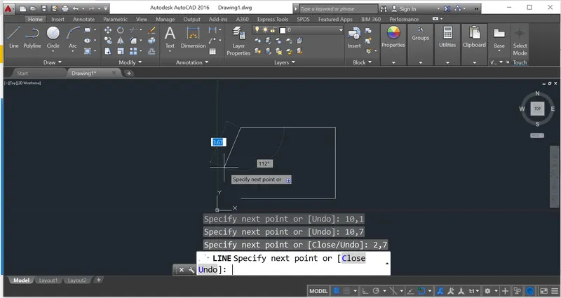
STEP 7: On continuing the line command, we need to specify the next point with respect to the first point specified in the Line command. Now the dimension in the X-direction is 0 units and in the opposite Y-direction is 2 units, so w.r.t. previous point drawn, this accordingly needs to be subtracted in the y-direction and added in the x-direction to the origin point (2,1). So our next point is 2,1 and this needs to be entered in the command tab. Now we need to close the line command.
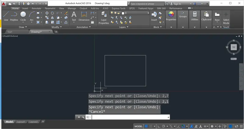
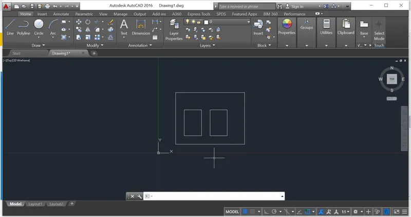
STEP 8: As per the image, we need to set a new first point using the line command. This point needs to be 3,2 as it is 3 units in x-direction and at 2 units from y-direction w.r.t. 0,0 .
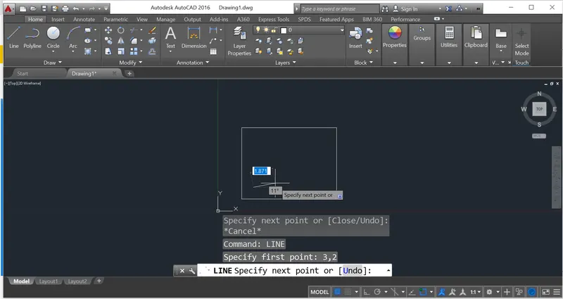
STEP 9: On continuing the line command, we need to specify the next point with respect to the first point specified in the Line command. Now the dimension in the X-direction is 2 units and in the Y-direction is 0 units, so w.r.t. previous point drawn, this accordingly needs to be added to the origin point (3,2). So our next point is 5,2 and this needs to be entered in the command tab.
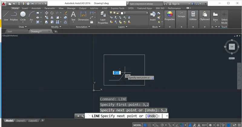
STEP 10: On continuing the line command, we need to specify the next point with respect to the first point specified in the Line command. Now the dimension in the X-direction is 0 units and in the Y-direction is 3 units, so w.r.t. previous point drawn, this accordingly needs to be added to the origin point (3,2). So our next point is 5,5 and this needs to be entered in the command tab.
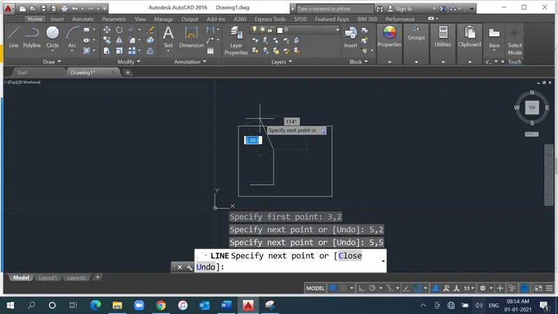
STEP 11: On continuing the line command, we need to specify the next point with respect to the first point specified in the Line command. Now the dimension in the opposite X-direction is 2 units and in the Y-direction is 0 units, so w.r.t. previous point drawn, this accordingly needs to be subtracted in the x-direction and added in the y-direction to the origin point (3,2). So our next point is 3,5 and this needs to be entered in the command tab
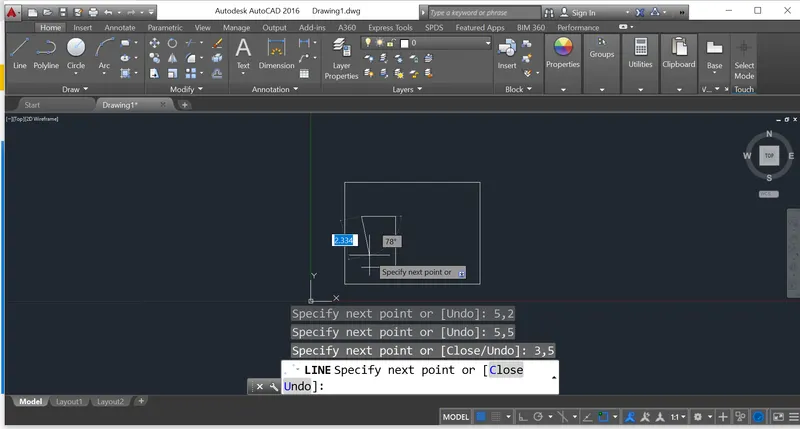
STEP 12: On continuing the line command, we need to specify the next point with respect to the first point specified in the Line command. Now the dimension in the X-direction is 0 units and in the opposite Y-direction is 3 units, so w.r.t. previous point drawn, this accordingly needs to be subtracted in the y-direction and added in the x-direction to the origin point (3,2). So our next point is 3,2 and this needs to be entered in the command tab. Now we need to close the line command.
STEP 13: As per the image, we need to set a new first point using the line command. This point needs to be 6,2 as it is 6 units in x-direction and at 2 units from y-direction w.r.t. 0,0 .
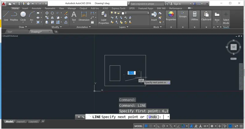
STEP 14: On continuing the line command, we need to specify the next point with respect to the first point specified in the Line command. Now the dimension in the X-direction is 2 units and in the Y-direction is 0 units, so w.r.t. previous point drawn, this accordingly needs to be added to the origin point (6,2). So our next point is 8,2 and this needs to be entered in the command tab.
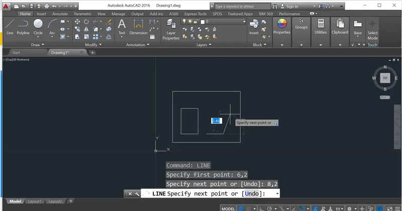
STEP 15: On continuing the line command, we need to specify the next point with respect to the first point specified in the Line command. Now the dimension in the X-direction is 0 units and in the Y-direction is 3 units, so w.r.t. previous point drawn, this accordingly needs to be added to the origin point (6,2). So our next point is 8,5 and this needs to be entered in the command tab.
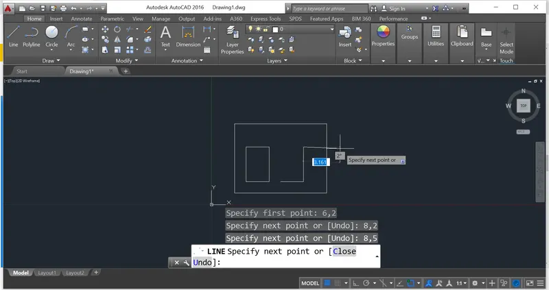
STEP 16: On continuing the line command, we need to specify the next point with respect to the first point specified in the Line command. Now the dimension in the opposite X-direction is 2 units and in the Y-direction is 0 units, so w.r.t. previous point drawn, this accordingly needs to be subtracted in the x-direction and added in the y-direction to the origin point (6,2). So our next point is 6,5 and this needs to be entered in the command tab
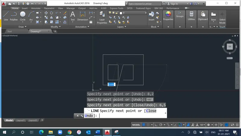
STEP 17: On continuing the line command, we need to specify the next point with respect to the first point specified in the Line command. Now the dimension in the X-direction is 0 units and in the opposite Y-direction is 3 units, so w.r.t. previous point drawn, this accordingly needs to be subtracted in the y-direction and added in the x-direction to the origin point (6,2). So our next point is 6,2 and this needs to be entered in the command tab. Now we need to close the line command.
STEP 1: On opening the AutoCad software, setup the units to Imperial template and decimal system to 0.000 .
STEP 2: Set the limits in the command tab using "LIM" before drafting.
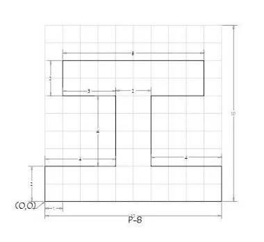
STEP 3: Once the limits are set, using Line tool, specify the first point (0,0).
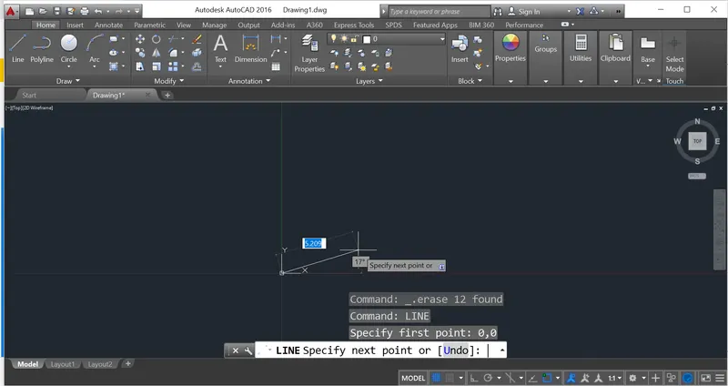
STEP 4: Now the dimension in the X-direction is 10 units and in the Y-direction is 0 units, so this accordingly needs to be added to the origin point (0,0). So our next point is 10,0 and this needs to be entered in the command tab.
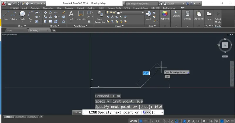
STEP 5: On continuing the line command, we need to specify the next point with respect to the first point specified in the Line command. Now the dimension in the X-direction is 0 units and in the Y-direction is 2 units, so w.r.t. previous point drawn, this accordingly needs to be added to the origin point (0,0). So our next point is 10,2 and this needs to be entered in the command tab.
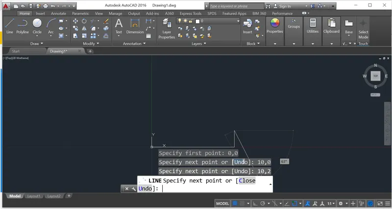
STEP 6: On continuing the line command, we need to specify the next point with respect to the first point specified in the Line command. Now the dimension in the opposite X-direction is 4 units and in the Y-direction is 0 units, so w.r.t. previous point drawn, this accordingly needs to be subtracted in x-direction and added in y-direction to the origin point (0,0). So our next point is 6,2 and this needs to be entered in the command tab
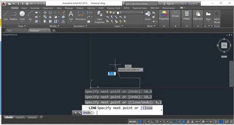
STEP 7: On continuing the line command, we need to specify the next point with respect to the first point specified in the Line command. Now the dimension in the X-direction is 0 units and in the Y-direction is 4 units, so w.r.t. previous point drawn, this accordingly needs to be added to the origin point (0,0). So our next point is 6,6 and this needs to be entered in the command tab.
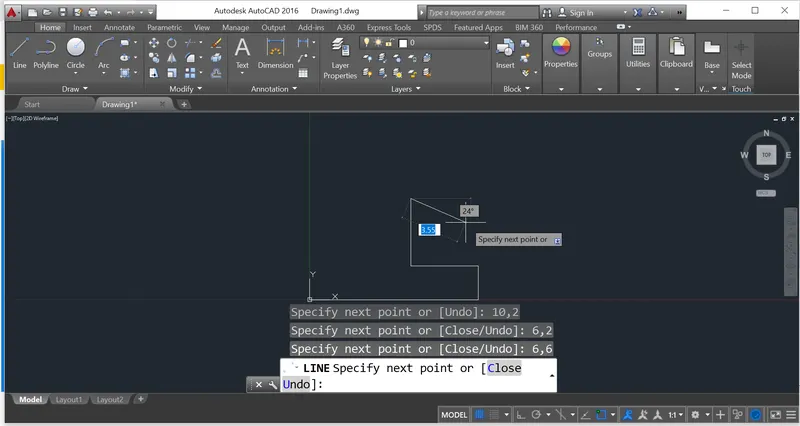
STEP 8: On continuing the line command, we need to specify the next point with respect to the first point specified in the Line command. Now the dimension in the X-direction is 3 units and in the opposite Y-direction is 0 units, so w.r.t. previous point drawn, this accordingly needs to be added to the origin point (0,0). So our next point is 9,6 and this needs to be entered in the command tab.
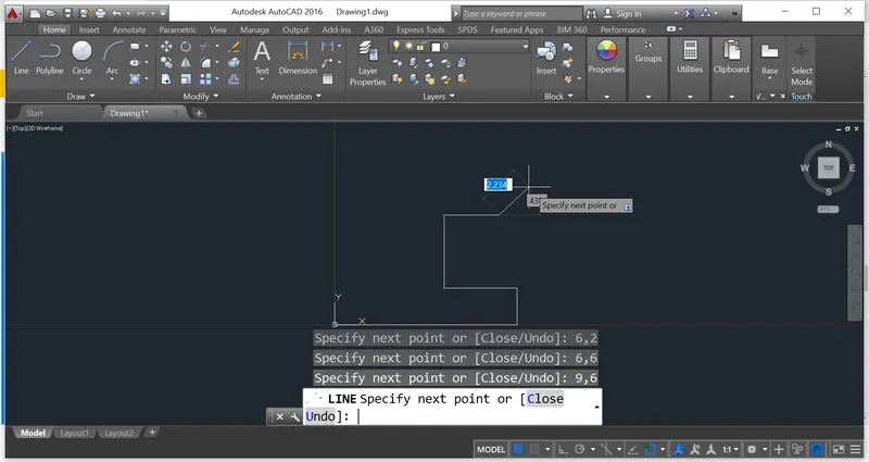
STEP 9: On continuing the line command, we need to specify the next point with respect to the first point specified in the Line command. Now the dimension in the X-direction is 0 units and in the Y-direction is 2 unit, so w.r.t. previous point drawn, this accordingly needs to be added to the origin point (0,0). So our next point is 9,8 and this needs to be entered in the command tab.
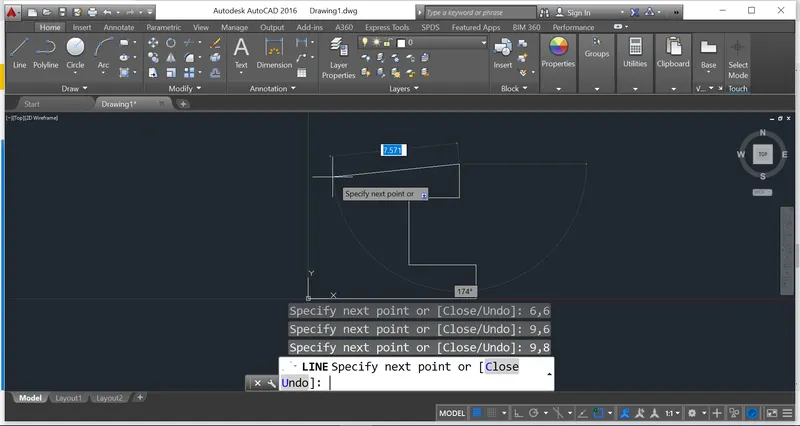
STEP 10: On continuing the line command, we need to specify the next point with respect to the first point specified in the Line command. Now the dimension in the opposite X-direction is 7 units and in the Y-direction is 0 units, so w.r.t. previous point drawn, this accordingly needs to be subtracted in x-direction and added in y-direction to the origin point (0,0). So our next point is 1,8 and this needs to be entered in the command tab
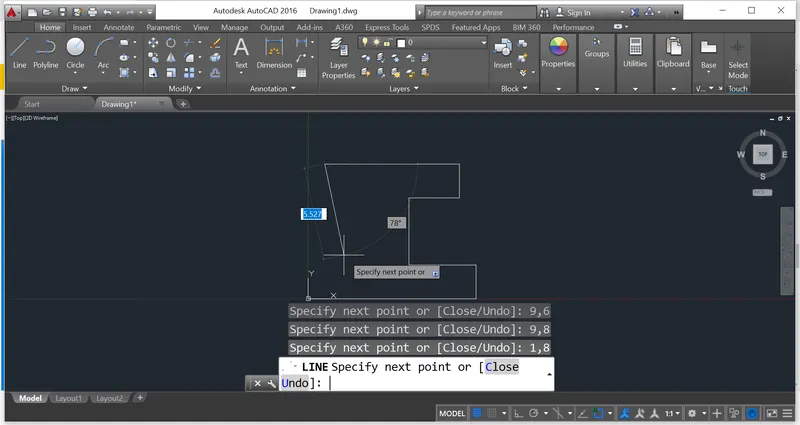
STEP 11: On continuing the line command, we need to specify the next point with respect to the first point specified in the Line command. Now the dimension in the X-direction is 0 units and in the opposite Y-direction is 2 units, so w.r.t. previous point drawn, this accordingly needs to be subtracted in y-direction and added in x-direction to the origin point (0,0). So our next point is 1,6 and this needs to be entered in the command tab

STEP 12: On continuing the line command, we need to specify the next point with respect to the first point specified in the Line command. Now the dimension in the X-direction is 3 units and in the Y-direction is 0 unit, so w.r.t. previous point drawn, this accordingly needs to be added to the origin point (0,0). So our next point is 4,6 and this needs to be entered in the command tab.
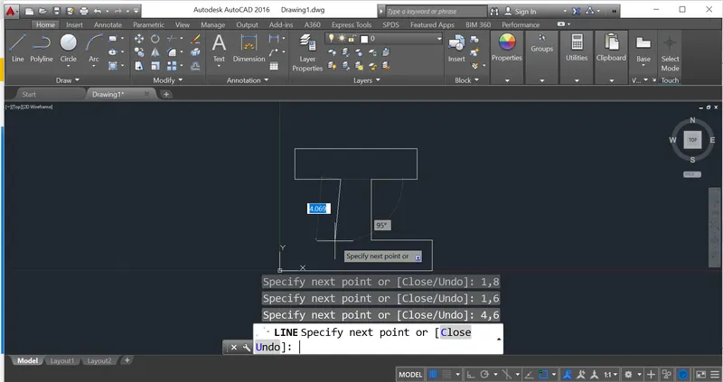
STEP 13: On continuing the line command, we need to specify the next point with respect to the first point specified in the Line command. Now the dimension in the X-direction is 0 units and in the opposite Y-direction is 4 units, so w.r.t. previous point drawn, this accordingly needs to be subtracted in y-direction and added in x-direction to the origin point (0,0). So our next point is 4,2 and this needs to be entered in the command tab
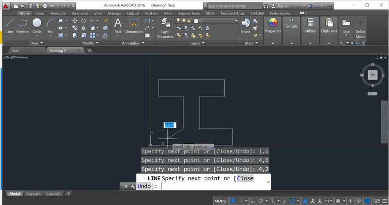
STEP 14: On continuing the line command, we need to specify the next point with respect to the first point specified in the Line command. Now the dimension in the opposite X-direction is 2 units and in the Y-direction is 0 units, so w.r.t. previous point drawn, this accordingly needs to be subtracted in x-direction and added in y-direction to the origin point (0,0). So our next point is 0,2 and this needs to be entered in the command tab
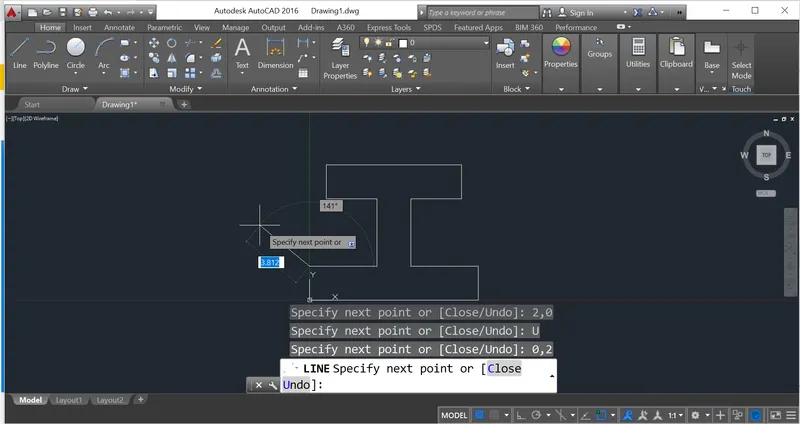
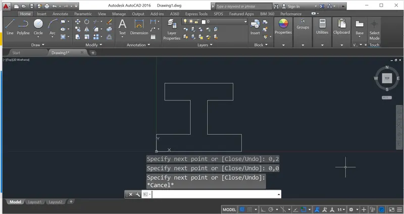
STEP 15: Now the final step is to insert the first coordinate point of the image to complete the drawing and the ESC to close the Line command.
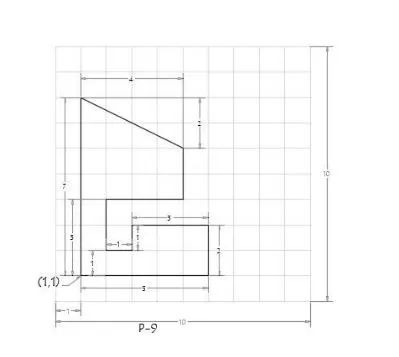
STEP 1: On opening the AutoCad software, setup the units to Imperial template and decimal system to 0.000 .
STEP 2: Set the limits in the command tab using "LIM" before drafting.
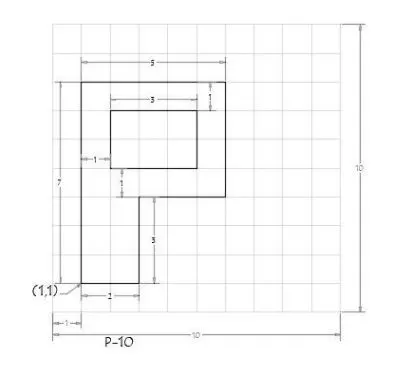
STEP 3: Once the limits are set, using Line tool, specify the first point (1,1).
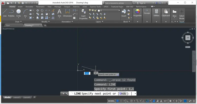
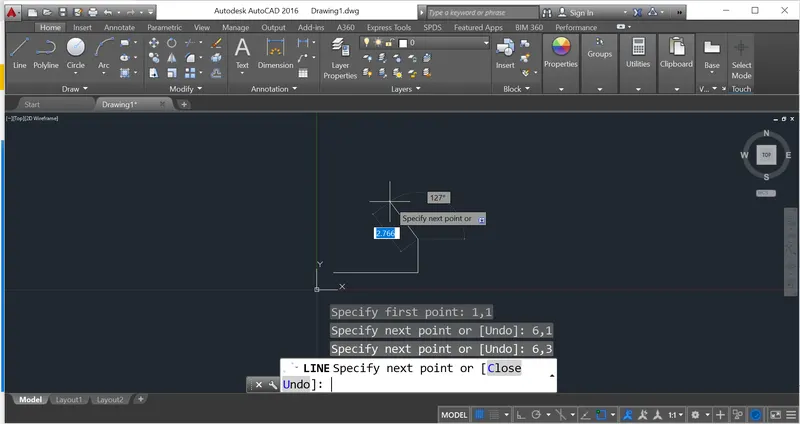
STEP 4: Now the dimension in the X-direction is 5 units and in the Y-direction is 0 units, so this accordingly needs to be added to the origin point (1,1). So our next point is 6,1 and this needs to be entered in the command tab.
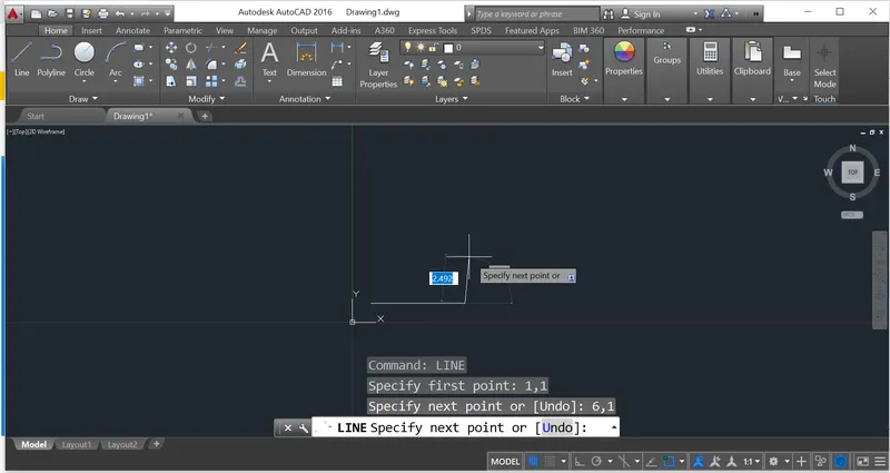
STEP 5: On continuing the line command, we need to specify the next point with respect to the first point specified in the Line command. Now the dimension in the X-direction is 0 units and in the Y-direction is 2 units, so w.r.t. previous point drawn, this accordingly needs to be added to the origin point (1,1). So our next point is 6,3 and this needs to be entered in the command tab.
STEP 6: On continuing the line command, we need to specify the next point with respect to the first point specified in the Line command. Now the dimension in the opposite X-direction is 3 units and in the Y-direction is 0 units, so w.r.t. previous point drawn, this accordingly needs to be subtracted in x-direction and added in y-direction to the origin point (1,1). So our next point is 3,3 and this needs to be entered in the command tab
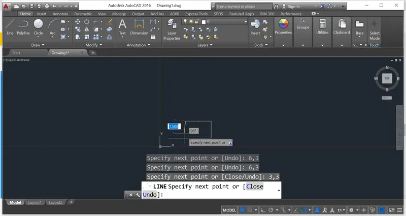
STEP 7: On continuing the line command, we need to specify the next point with respect to the first point specified in the Line command. Now the dimension in the X-direction is 0 units and in the opposite Y-direction is 1 units, so w.r.t. previous point drawn, this accordingly needs to be subtracted in y-direction and added in x-direction to the origin point (1,1). So our next point is 3,2 and this needs to be entered in the command tab
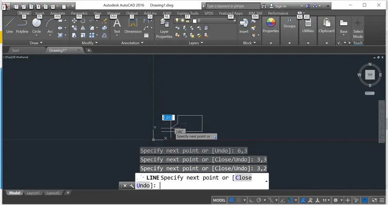
STEP 8: On continuing the line command, we need to specify the next point with respect to the first point specified in the Line command. Now the dimension in the opposite X-direction is 1 units and in the Y-direction is 0 units, so w.r.t. previous point drawn, this accordingly needs to be subtracted in x-direction and added in y-direction to the origin point (1,1). So our next point is 2,2 and this needs to be entered in the command tab
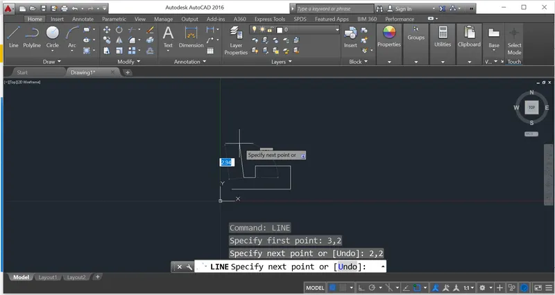
STEP 9: On continuing the line command, we need to specify the next point with respect to the first point specified in the Line command. Now the dimension in the X-direction is 0 units and in the Y-direction is 2 unit, so w.r.t. previous point drawn, this accordingly needs to be added to the origin point (1,1). So our next point is 2,4 and this needs to be entered in the command tab.
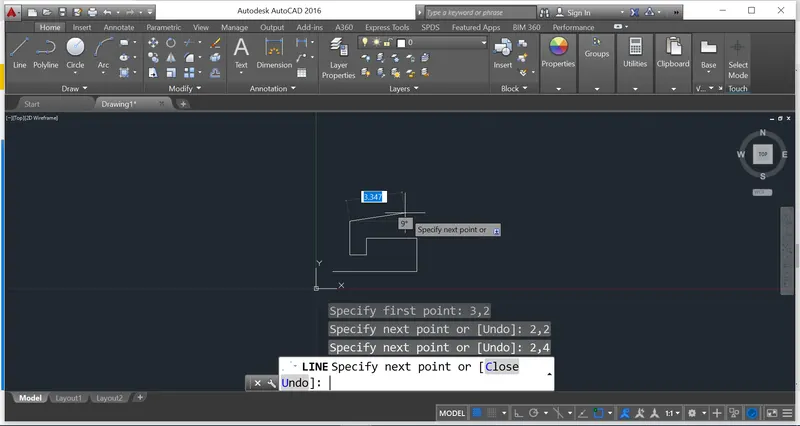
STEP 10: On continuing the line command, we need to specify the next point with respect to the first point specified in the Line command. Now the dimension in the X-direction is 3 units and in the Y-direction is 0 unit, so w.r.t. previous point drawn, this accordingly needs to be added to the origin point (1,1). So our next point is 5,4 and this needs to be entered in the command tab.
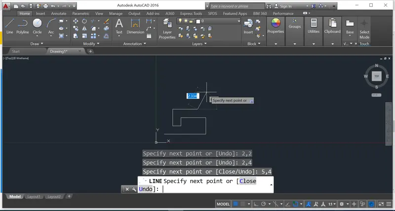
STEP 11: On continuing the line command, we need to specify the next point with respect to the first point specified in the Line command. Now the dimension in the X-direction is 0 units and in the Y-direction is 2 unit, so w.r.t. previous point drawn, this accordingly needs to be added to the origin point (1,1). So our next point is 5,6 and this needs to be entered in the command tab.
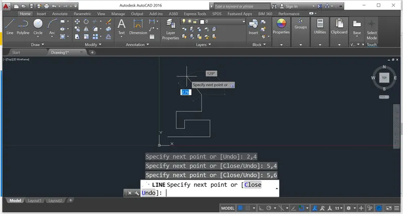
STEP 12: On continuing the line command, we need to specify the next point with respect to the first point specified in the Line command. Now the dimension in the opposite X-direction is 4 units and in the Y-direction is 2 units, so w.r.t. previous point drawn, this accordingly needs to be subtracted in x-direction and added in y-direction to the origin point (1,1). So our next point is 1,8 and this needs to be entered in the command tab
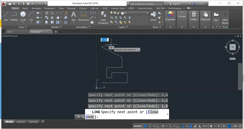
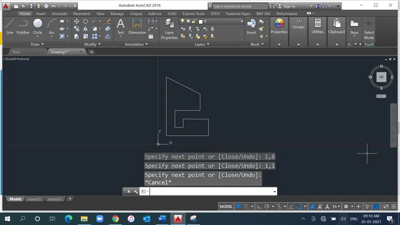
STEP 13: Now the final step is to insert the first coordinate point of the image to complete the drawing and the ESC to close the Line command.
STEP 1: On opening the AutoCad software, setup the units to Imperial template and decimal system to 0.000 .
STEP 2: Set the limits in the command tab using "LIM" before drafting.
STEP 3: Once the limits are set, using Line tool, specify the first point (1,1).
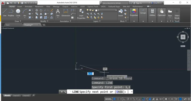
STEP 4: Now the dimension in the X-direction is 2 units and in the Y-direction is 0 units, so this accordingly needs to be added to the origin point (1,1). So our next point is 3,1 and this needs to be entered in the command tab.
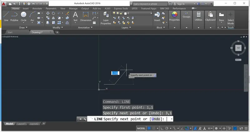
STEP 5: On continuing the line command, we need to specify the next point with respect to the first point specified in the Line command. Now the dimension in the X-direction is 0 units and in the Y-direction is 3 units, so w.r.t. previous point drawn, this accordingly needs to be added to the origin point (1,1). So our next point is 3,4 and this needs to be entered in the command tab.
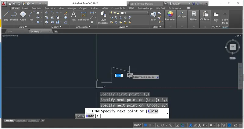
STEP 6: On continuing the line command, we need to specify the next point with respect to the first point specified in the Line command. Now the dimension in the X-direction is 3 units and in the Y-direction is 0 units, so w.r.t. previous point drawn, this accordingly needs to be added to the origin point (1,1). So our next point is 6,4 and this needs to be entered in the command tab.
STEP 7:On continuing the line command, we need to specify the next point with respect to the first point specified in the Line command. Now the dimension in the X-direction is 0 units and in the Y-direction is 4 units, so w.r.t. previous point drawn, this accordingly needs to be added to the origin point (1,1). So our next point is 6,8 and this needs to be entered in the command tab.
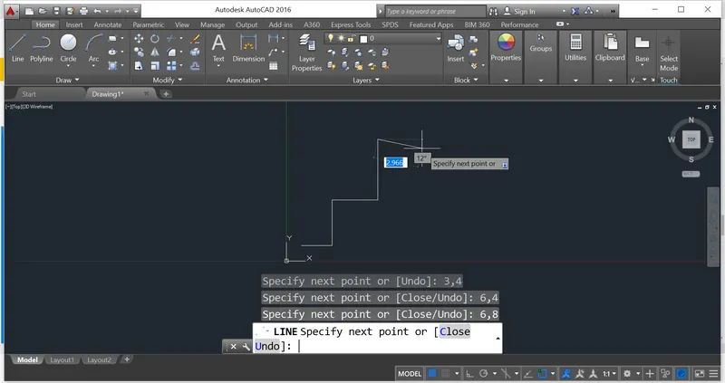
STEP 8: On continuing the line command, we need to specify the next point with respect to the first point specified in the Line command. Now the dimension in the opposite X-direction is 5 units and in the Y-direction is 0 units, so w.r.t. previous point drawn, this accordingly needs to be subtracted in the x-direction and added in the y-direction to the origin point (1,1). So our next point is 1,8 and this needs to be entered in the command tab
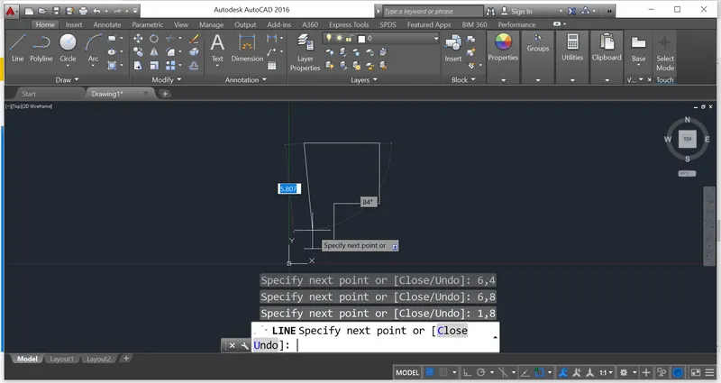
STEP 9: On continuing the line command, we need to specify the next point with respect to the first point specified in the Line command. Now the dimension in the X-direction is 0 units and in the opposite Y-direction is 7 units, so w.r.t. previous point drawn, this accordingly needs to be subtracted in the y-direction and added in the x-direction to the origin point (1,1). So our next point is 1,1 and this needs to be entered in the command tab. Now we need to close the line command.
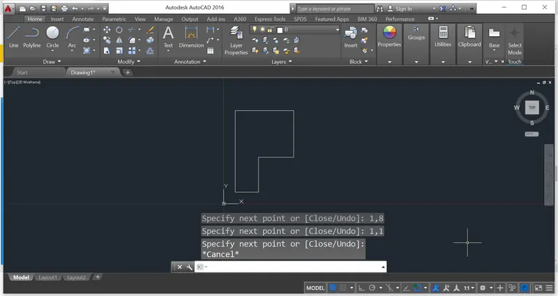
STEP 10: As per the image, we need to set a new first point using the line command. This point needs to be 2,5 as it is 2 units in x-direction and at 5 units from y-direction w.r.t. 0,0 .
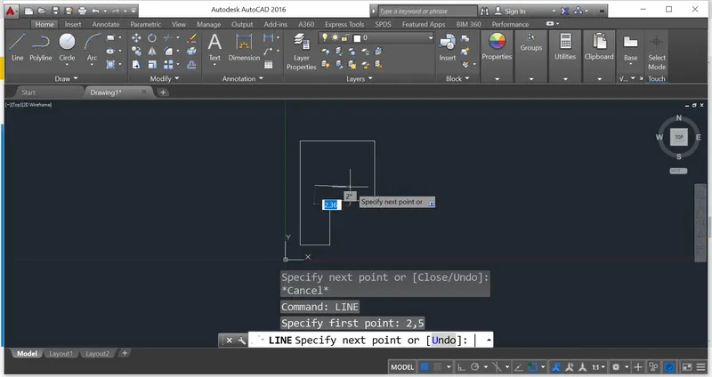
STEP 11: On continuing the line command, we need to specify the next point with respect to the first point specified in the Line command. Now the dimension in the X-direction is 3 units and in the Y-direction is 0 units, so w.r.t. previous point drawn, this accordingly needs to be added to the origin point (2,5). So our next point is 5,5 and this needs to be entered in the command tab.
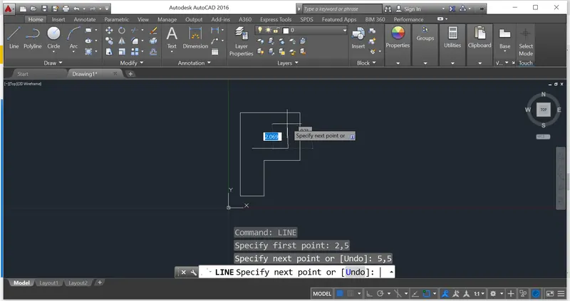
STEP 12: On continuing the line command, we need to specify the next point with respect to the first point specified in the Line command. Now the dimension in the X-direction is 0 units and in the Y-direction is 2 units, so w.r.t. previous point drawn, this accordingly needs to be added to the origin point (2,5). So our next point is 5,7 and this needs to be entered in the command tab.
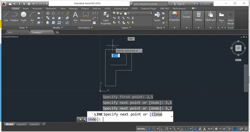
STEP 13: On continuing the line command, we need to specify the next point with respect to the first point specified in the Line command. Now the dimension in the opposite X-direction is 3 units and in the Y-direction is 0 units, so w.r.t. previous point drawn, this accordingly needs to be subtracted in the x-direction and added in the y-direction to the origin point (2,5). So our next point is 2,7 and this needs to be entered in the command tab
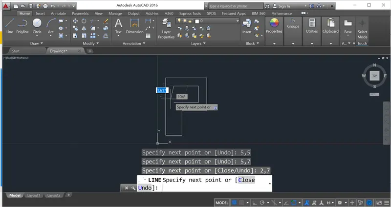
STEP 14: On continuing the line command, we need to specify the next point with respect to the first point specified in the Line command. Now the dimension in the X-direction is 0 units and in the opposite Y-direction is 2 units, so w.r.t. previous point drawn, this accordingly needs to be subtracted in the y-direction and added in the x-direction to the origin point (2,5). So our next point is 2,5 and this needs to be entered in the command tab. Now we need to close the line command.
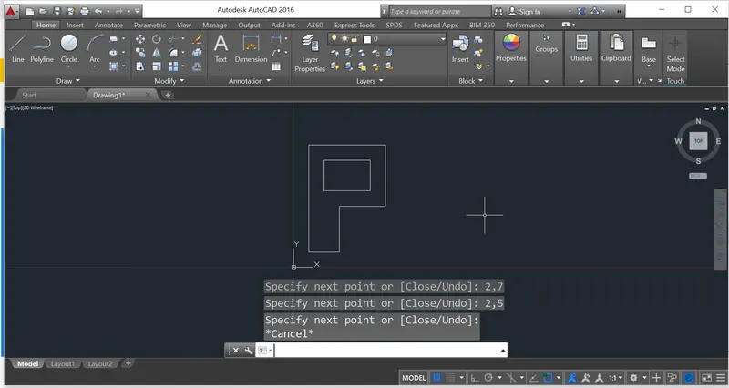
- CONCLUSION: The above geometries from P1 to P10 have been created in coordinates system in AutoCad using Line tool.
2.
- AIM: To Create the geometries using Line tool or circle tool wherever required for the below images using the coordinates system method in AutoCad.
- PROCEDURE: The step by step procedure for each picture is given below:
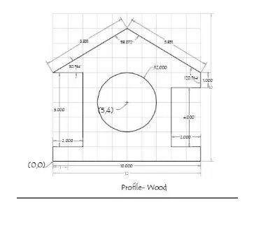
STEP 1: On opening the AutoCad software, setup the units to Imperial template and decimal system to 0.000 .
STEP 2: Set the limits in the command tab using "LIM" before drafting.
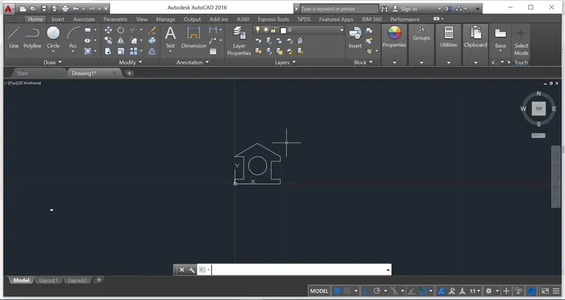
STEP 3: Once the limits are set, using Line tool, specify the first point (0,0).
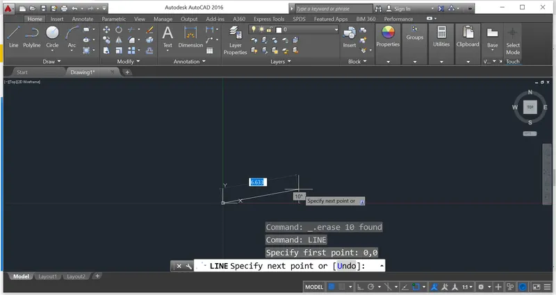
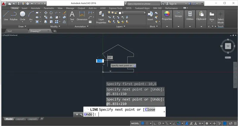
STEP 4: Specify the next point using the dimension w.r.t the previous coordinate (first point specified) using "@". Here the next point shall be @10,0
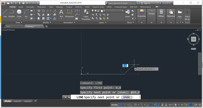
STEP 5:
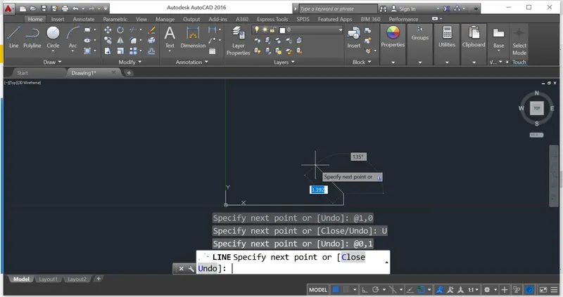
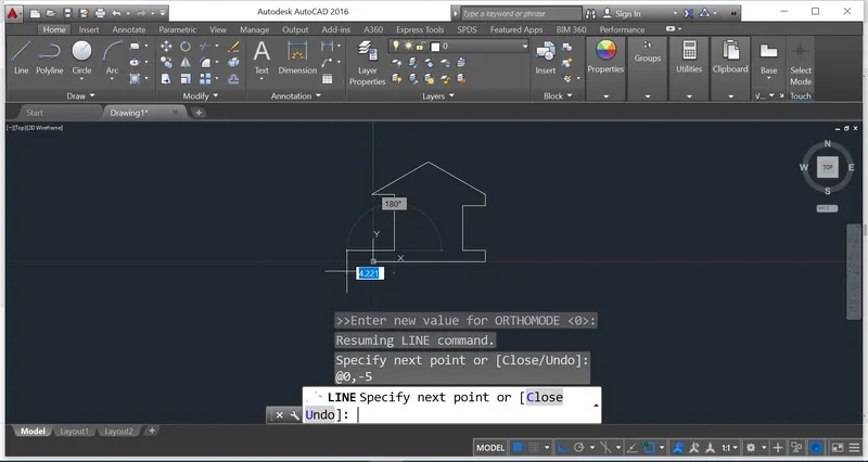
STEP 6: Here the dimension is 2 units in opposite x-direction, hence @-2,0
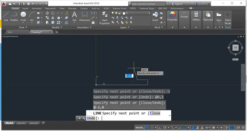
STEP 7:
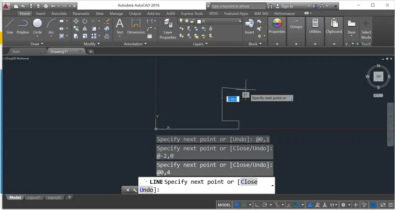
STEP 8:
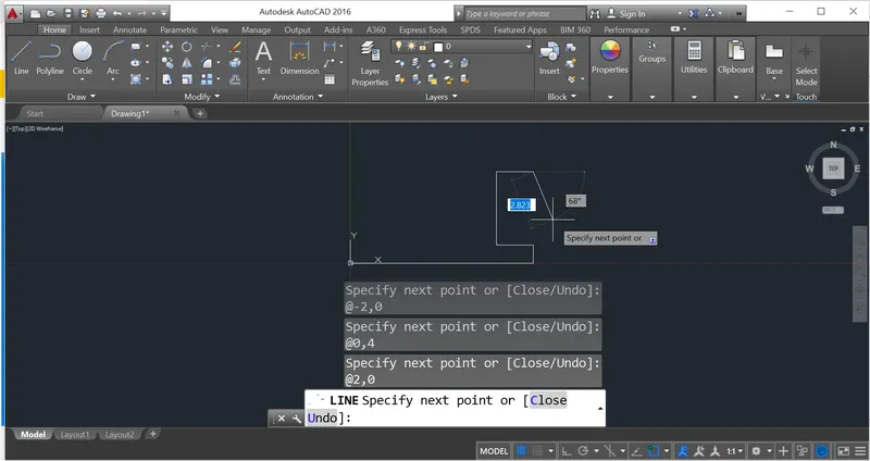
STEP 9:
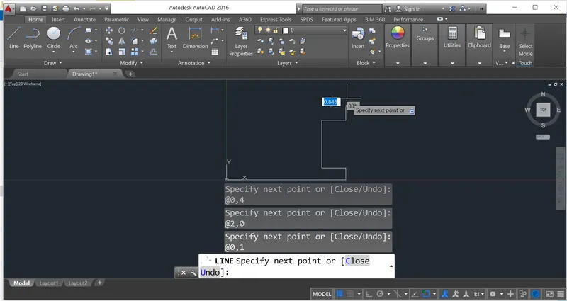
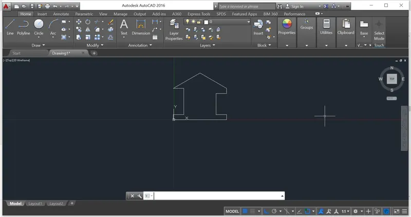
STEP 10: Here as per the image, we need to mention the angle w.r.t. X and Y direction along with the dimension. So the next point should be specified as @5.831<150.
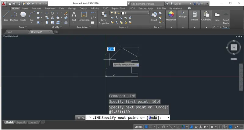
STEP 11:
STEP 12:
STEP 13:
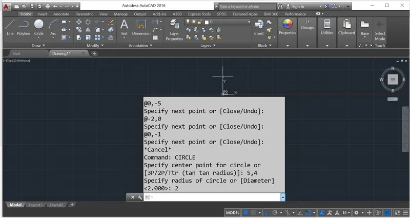
STEP 14: To insert circle, we need to enter CIRCLE command, and specify and the centre point and radius
STEP 1: On opening the AutoCad software, setup the units to Imperial template and decimal system to 0.000 .
STEP 2: Set the limits in the command tab using "LIM" before drafting.
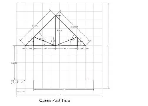
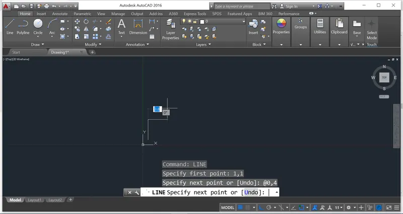
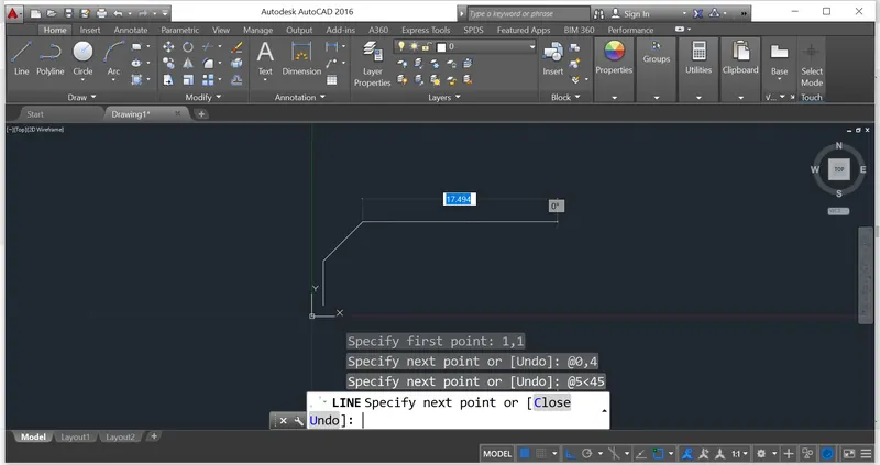
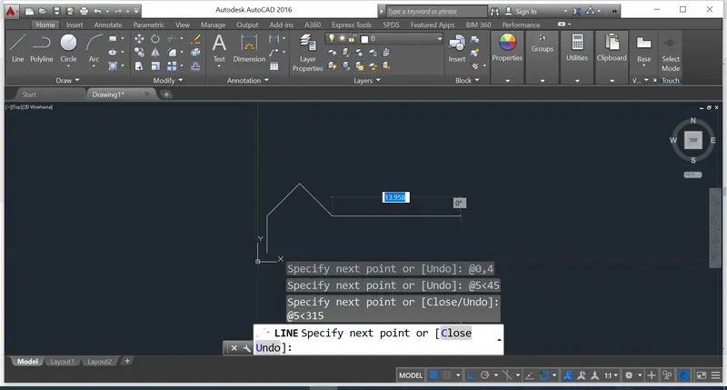
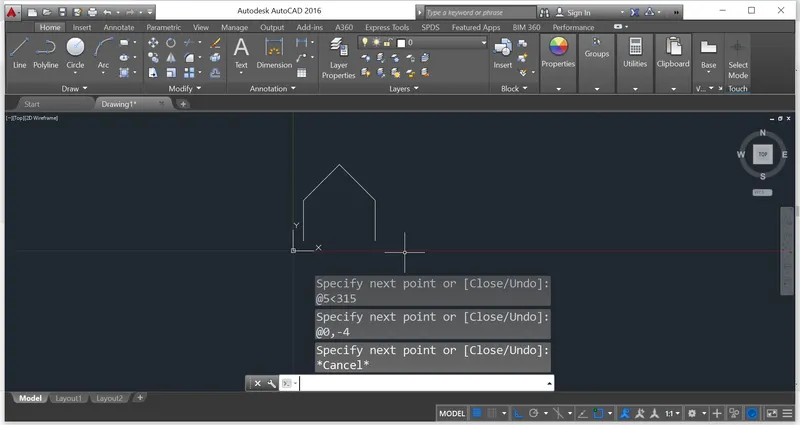
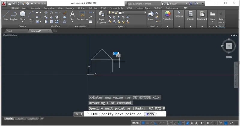
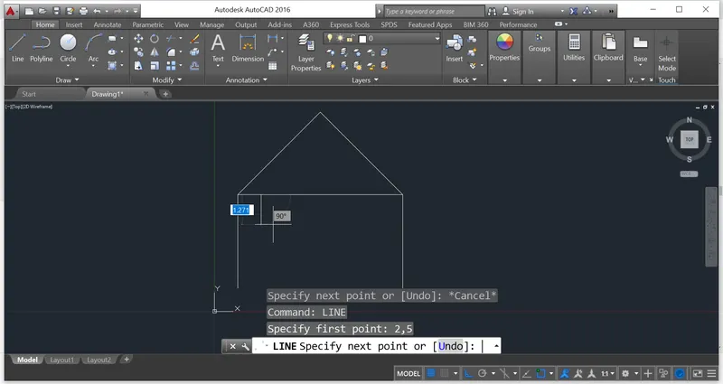
STEP 3: Once the limits are set, using Line tool, specify the first point (1,1).
STEP 4: Specify the next point using the dimension w.r.t the previous coordinate (first point specified) using "@". Here the next point shall be @0,4
STEP 5:
STEP 6:
STEP 7:
STEP 8:
STEP 9:
STEP 10:
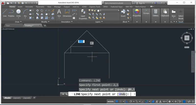
STEP 11:
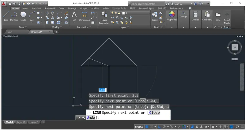
STEP 12:
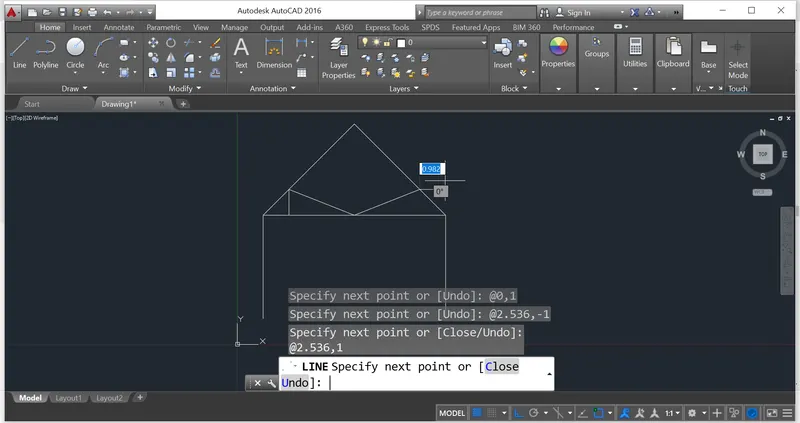
STEP 13:
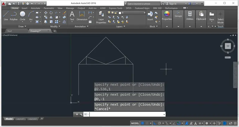
STEP 14:
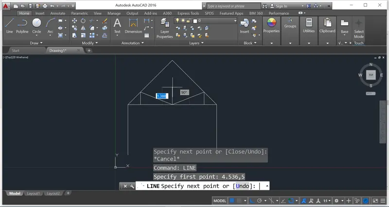
STEP 15:
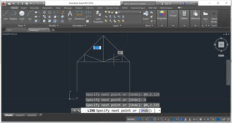
STEP 16:
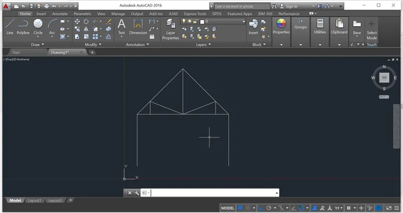
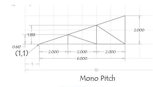
STEP 1: On opening the AutoCad software, setup the units to Imperial template and decimal system to 0.000 .
STEP 2: Set the limits in the command tab using "LIM" before drafting.
STEP 3: Once the limits are set, using Line tool, specify the first point (1,1).
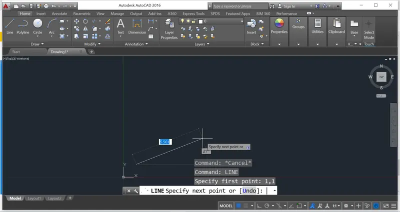
STEP 4: Specify the next point using the dimension w.r.t the previous coordinate (first point specified) using "@". Here the next point shall be @1,1
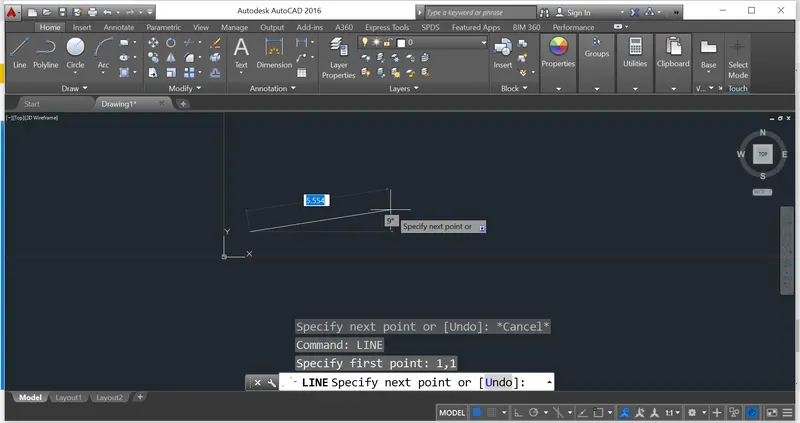
STEP 5:
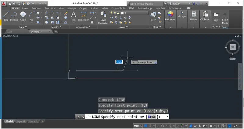
STEP 6:
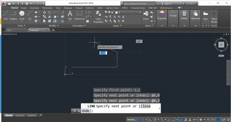
STEP 7:
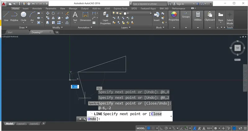
STEP 8:
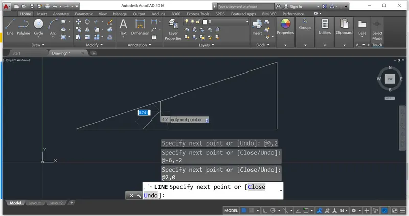
STEP 9:
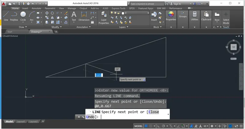
STEP 10:
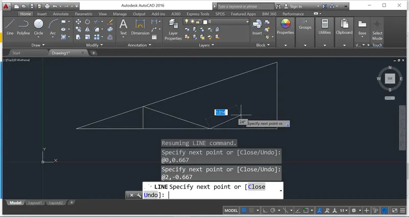
STEP 11:
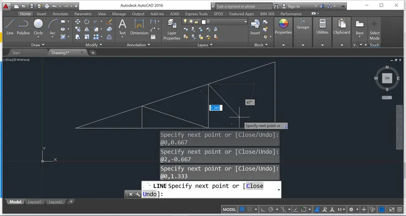
STEP 12:
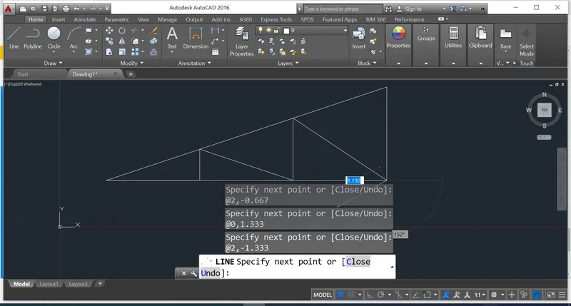
STEP 13:
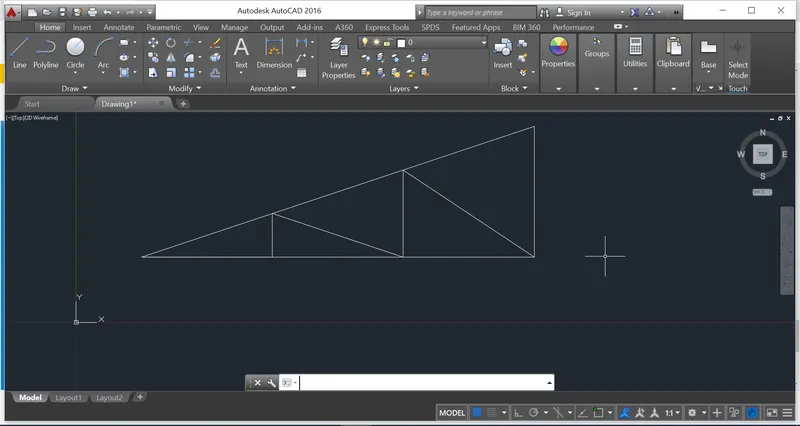
- CONCLUSION: The above geometries have been created in coordinates system in AutoCad using Line tool and Circle tool wherever required.