Aston Martin ONE-77 Challenge-11 (Project)
Surface Modelling of Aston Martin One - 77 Car.
Objective - Our objective here is to make a detailed surface model of Aston Martin One - 77 car.
The Aston Martin One-77 is a two-door, two-seater flagship sports car built by the British car manufacturer Aston Martin. Its is a very beautiful car. And we will be making it in Solidworks. It includes Surface Modelling and Solid Modelling the features used in here are mostly basic but there are some areas where advanced modelling skills are required, to complete this successfully a user need to have a very good knowledge of how Solidworks works and where and what are the features which we will be using it, more on that is discussed below.
Approach -
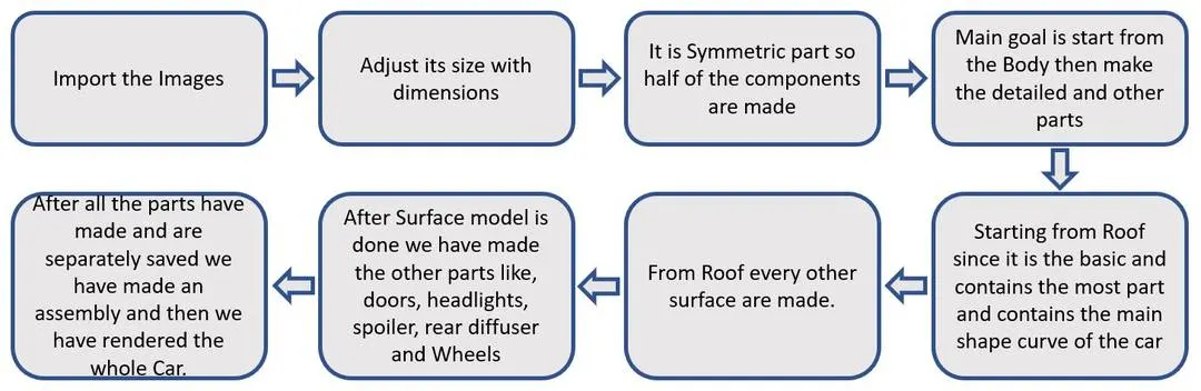
FIG. 0.0
There is one main body which consists -
01 - Car Frame
02 - Windshields
03 - Hood
04 - Doors
05 - Rear Diffuser
06 - Grille
07 - Headlight
08- Wheels
09 - Emblem
All the above parts are modelled in the software itself, either by Surfacing or by Solid Modelling. Parts like Car Frame, Windshields etc are made with Surfacing and parts like Brakes, Caliper, Grille, Tyre, Rim are made with Solid Modelling.
Moving on to the Features and Tools that are used are viz. -
A - Sketch Tools -
01 - Line
02 - Circle
03 - Slot
04 - Rectangle
most importantly,
05 - Spline
B - Features -
01 - Extrude
02 - Extruded Cut
03 - Revolve
04 - Revolve Cut
05 - Fillet
06 - Chamfer
07 - Sweep
08 - Loft
09 - Project Curve
10 - Trim
11 - Thicken
12 - Draft
13 - Flex
14 - Combine
15 - Intersect
16 - Move/Copy
17 - Delete
18 - Split
19 - Mirror
20 - Pattern etc.
C - Surface Tools -
01 - Boundary Surface
02 - Fill Surface
03 - Split Line
04 - Knit Surface
05 - Loft
06 - Extrude
07 - Trim
08 - Extend
09 - Ruled
10 - Offset etc.
Now we will be covering every feature as we discuss the parts that we have made.
01 - Car Frame
Making the perfect aligned car frame is definitely not an easy task and to do so we have to use every feature that is listed above, now to start, we have SPLINE, it is basically a line but it has control points with which we can control the shape of it. We can add the length and angle to get the desired shape we can also align the control points, concerning the other lines or sketch parameters.
Now, our approach here in making the FRAME is -
Crete SPLINES and PROJECT it.
e.g. making two lines, one in Top and other in Side plane and then when we use project it, we will get a curve which, if seen from the top has the same property of the one we made on top and when seen from Side has the same property of the one we made on Side but the thing is it will be a SINGLE curve. Hope this makes sense.
Moving on, after we have made the curves and we have a patch we make a surface, for that we can use BOUNDARY/FIll.
Boundary surface uses Direction Lines to make a surface and that is why it has a fine and perfect shape and curvature of the lines and it is more preferred over any other surface tool, next Fill, it is what it is, it just uses the curves and fills the gap, there are some patches where boundary surface tool is not able to run e.g. a patch of 5 edges/curves. Moreover, we can even define the shape of the surface by giving Tangency/Curvature/Direction Vector/Normal to, to have a good surface quality.
After a surface is made and if we wish to use it we can, in many different ways, like, we can add the edge directly in making a patch, we can also project the curves on the surface and give it as a reference, another feature is, we can also use Split Line Curve, it is same as Project Curve but it just required a single curve and it can project directly on the surface.
At times like separation of the surfaces, we have to use Trim command it can be used to trim off the surface, it can be used with curves and Surface Intersections.
Now, what if, we want a surface and we want to have it as a separate part, e.g. making windshield, which has some thickness to it, and to edit it we will have to export that body and edit it sepeartely. So at times like this, we use OFFSET/COPY, it does what its name suggests it can either make an offset surface at some distance or can make a copy at that place as well, which is very useful.
Now there will be times when we will need to combine surfaces and work on them at the same time and at that time we use KNIT SURFACE it basically works same as COMBINE (it combines the bodies), but here it just KNITS the surface together, but here since these are comparable, KNIT has some other features like, GAP control which basically means that if we need to, we can make a watertight model, by using close tolerances.
Other features like, LOFT, Ruled surface these are just the features which are used to make the surfaces, e.g. LOFT it makes a surface by taking a reference/guideline and the Shape which is defined by the user. Ruled surface, creates surfaces that extend out in a specified direction from selected edges it can be either extended normal to, perpendicular etc. A similar tool/feature is EXTRUDE but we all know how it works, it just needs the curve can it can extend it in 3d (if SOLID modelling) or make a Surface (if SURFACE modelling) extrude feature gives us the freedom to the start point/endpoint, THIN feature, or DRAFT (an angle is added to the generation).
Next after that, we have just used MIRROR and made a duplicate exact body concerning the RIGHT PLANE.
This way a Frame can be modelled, again it is just Surfaces, no solid tool is used.
COMPLETED FRAME IS SHWON BELOW -
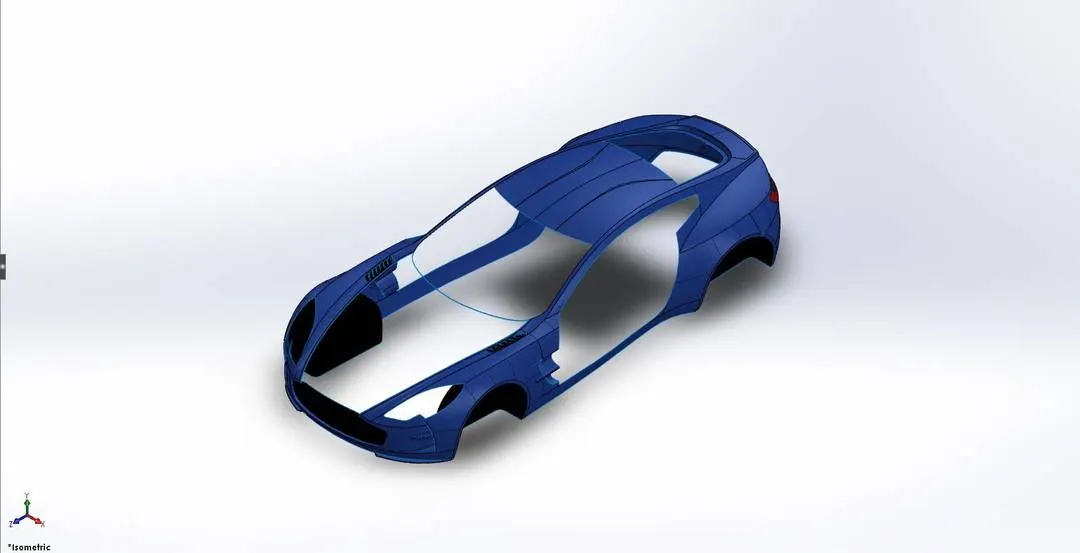
FIG. 1.1
NOT - THIS IS COMPLETED FILE ALL THE PARTS THAT ARE REMOVED HAVE ASSEMBLED AT THE END.
Now we move on to the easy part first ie.
02 - Windshields
The shape of the same is taken from the Frame (by using Offset/Copying), here we have used a home feature of the SOLIDWORKS for better visualization, i.e APPEARANCES this allows us to apply either 1. Material e.g. Metal, Plastic, Glass, Wood etc. or simply 2. Appearance (i.e. Colour). This part can be very creative dependent on the user because the appearance we add WILL get reflected in the rendering if it is GLOSS it will be shiny and if it will be Matte it will appear like that when we render it, so a countless number of possibilities are there.
For Windshields, we do not have much to do, but to add the offset and apply THICKEN which is easily understandable in solid modelling i.e. it creates a solid feature by thickening one or more adjacent surfaces but if the surface is to be thickened and it includes multiple adjacent surfaces then we need to knit the surfaces together before we thicken the surface. This, we have done to provide thickness to glass.
Now as explained above, it results in a SOLID body, and we do not need that. So for that, we can use, DELETE FACE / DELETE BODY command, we need to use DELETE FACE because we need a FACE to be removed if it would be an entire body, then we must use the DELETE BODY command.
NOTE - Now why we need to do this? It is because we need to KNIT the surfaces later and as SOLID BODY and a SURFACE BODY, can not be knitted together.
Moving on to the hood, it is simple and basic no extra feature/tool is required to model the HOOD, same goes for DOOR and Diffuser.
Find the Images below -
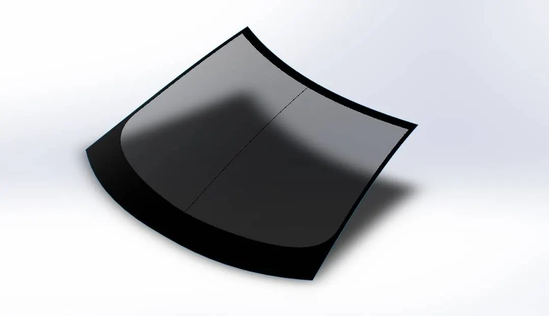
FIG 2.1
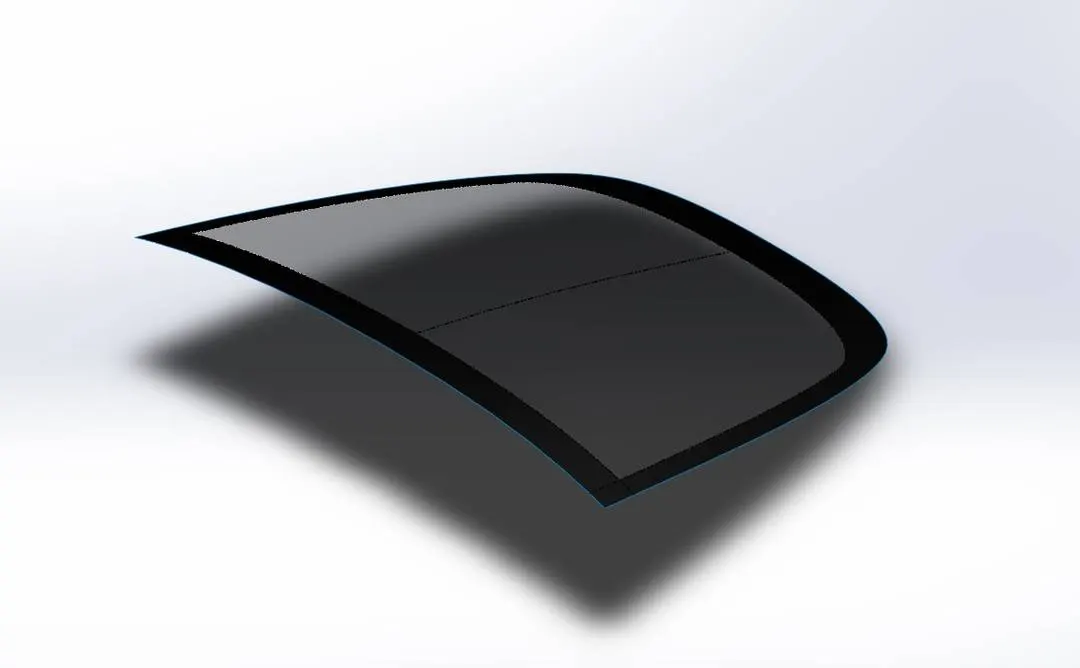
FIG. 2.2
03 - Hood
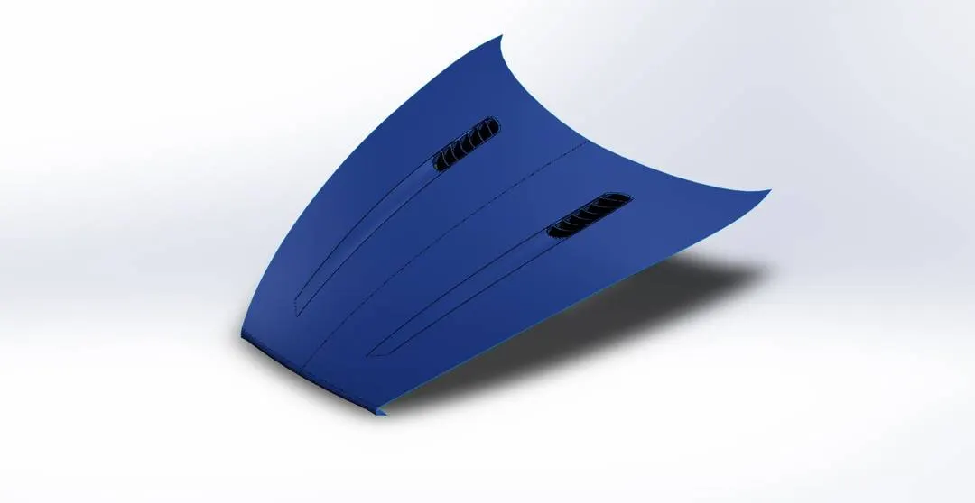
FIG. 3.1
04 - Doors
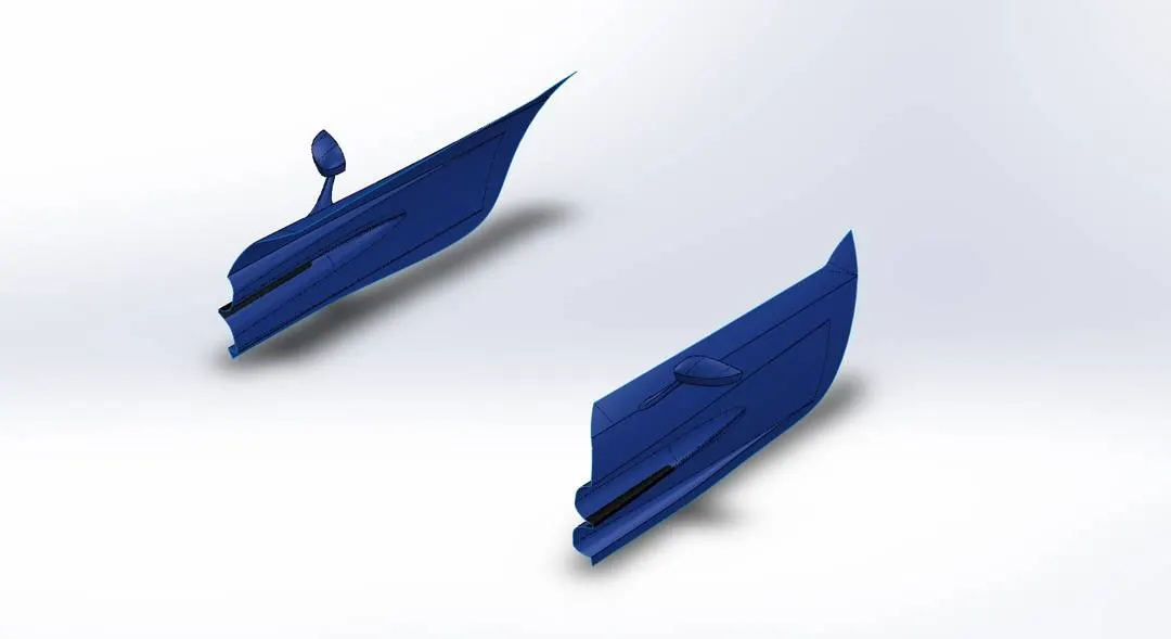
FIG. 4.1
05 - Rear Diffuser
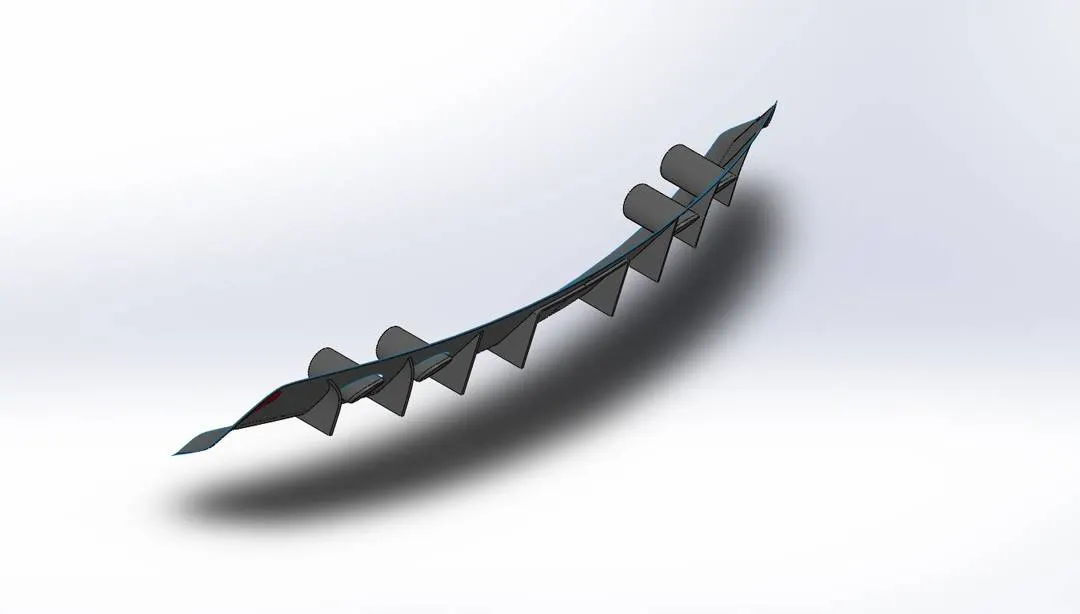
FIG 5.1
06 - Grille
To model this we have just used SPLINES (explained earlier), LINES, FILLETS. and for the Number Plate, we have used Extrude.
Lines - It is just a basic tool, it can be either made as construction line (for reference), Line, Centerline etc, also it as the ability to transform from Line to arc when dragged at the endpoint, it is very useful in making/giving the dimensions or to make the sketch constrain by giving the various constraints like Horizontal, Vertical, Tangent, MidPoint, Intersection etc.
FILLETS - These are just used to remove the sharp edges and make it soft or round, it has various uses as a uniform, variable, face etc.
CHAMFER - Works same as Fillet but instead of making a curvature it makes a STRAIGHT profile.
Consider the image.
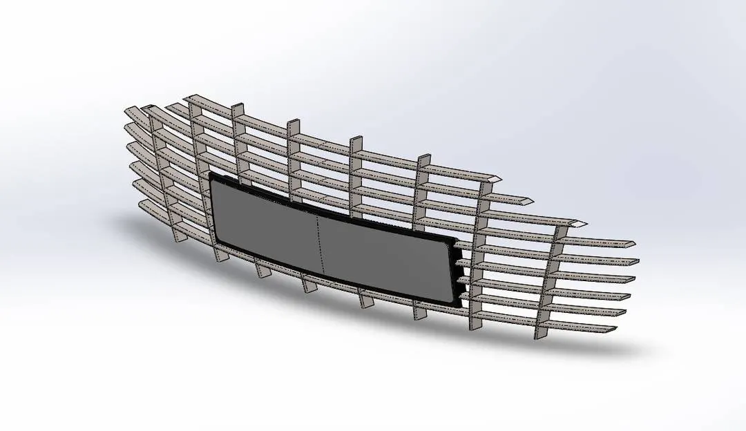
FIG. 6.1
07 - Headlights
This is same as grille combination of surfaces and solids. Here we have used various features like EXTRUE, THICKENED, REVOLVE, CUT WITH SURFACE, (which is used to cut/remove the bodies all it needs is a surface rest the ability is eaxctly the same as CUT EXTRUDE) MOVE/COPY BODY (it allows us to translate the selected body in X,Y or Z - Axis the same is possible with Rotate Sub Feature, more over we can select weather to keep a copy of the selected body or just tot move the entire body at the selected /preffered place/ co - ordinate) we have also used INTERSECT tool, this tool just like combine (which will be covering later on), requires the bodies and then the separate bodies which were selected is intersected by the feature and it will allow us to remove the body, all we need to do is make the selection and it will be removed. Here we can see the use of different material and appearances we have used Thick Glass for the Headlight Cover.
Consider the image -
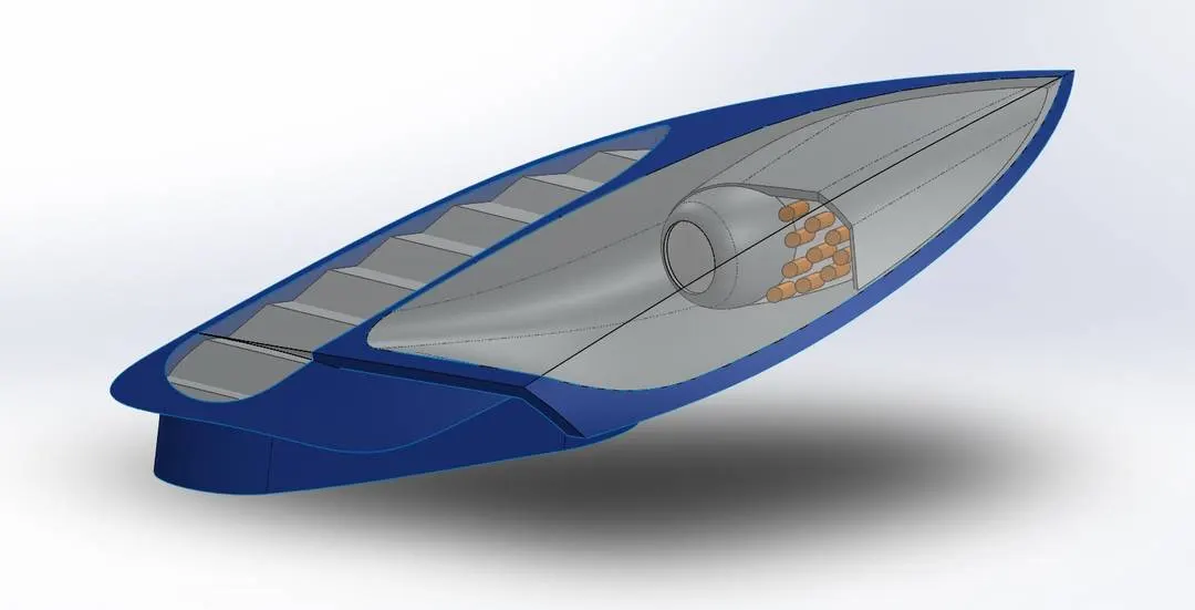
FIG - 7.1
08 - WHEELS.
This is divided into three parts -
1 - Tyre
2 - Calliper
3 - Rim
4 - Disk
We will be discussing all three separately every,
1 - Tyre
Here we have mainly used REVOLVE it allows us to make a circular body by taking the Profile/Sketch as input and AXIS of revolution as a reference on which the entire sketch gets revolved here also we have the freedom to define start/endpoints we also have the ability to define the angle by which the revolve takes place, it ahs both REVOLVE BOSS/CUT and the same thing for Surface as well.
EXTRUDED CUT it is just the same as EXTRUDE but instead of making a body it just removes the data it requires the sketch and the direction it can also flip the area around which we need to cut (e.g. inside of the sketch profile or the outside).
Now with this we can get the the over all shape of the tyre but we cannot get the grooves which gives the griop to the wheel, (well not that we need grip and friction in software but for realism we have made that as well).
Now since it is removal of material we think why not use CUT EXTRUE? Well we cannot, because we need the groove to follow the circular path, if we use the cut feature the bottom will be flat it will not be curved (following the profile of the tyre).
Now here we can have Two solutions, SWEEP or REVOLVE CUT. But it will be very difficult to visualize and give the axis to rotate around. so we will make use of SWEEP, this feature Sweep creates a base, cut, or surface by moving a profile (section) along a path. it can be simple as well las complex, the sweep geometry can be used by 2 thingds, The profile and the path, we can also make multiple profiles on a single path, depending on our conviency, since we need the material to be removed we have used SWEEP CUT. Consider the image. For the appearance we have used RUBBER.
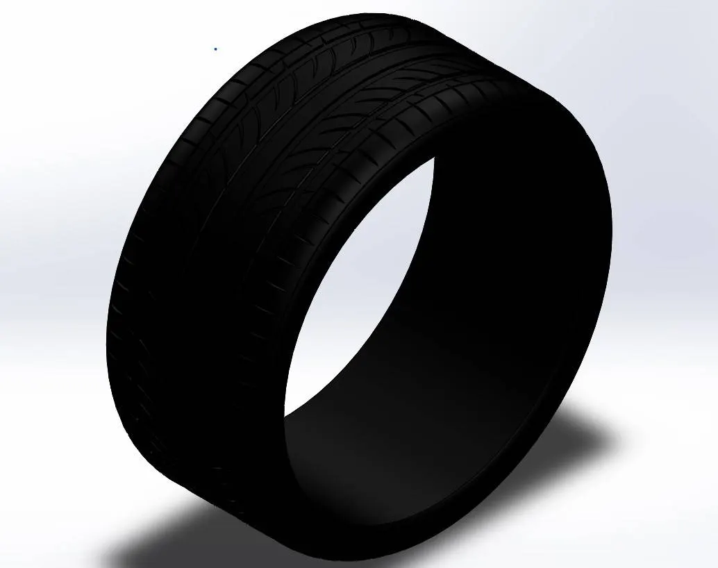
FIG 8.1
2 - Calliper
For the Calliper we have used Extrude, Extrude Cut, Revolve and Loft, Chamfer, Draft, Combine and Mirror. Every feature except Combine are explained above. So, COMBINE feature allows us to use 1. Add 2. Subract and 3. Common sub features which means exactly as the names, but output is same (a single body).
Check the image for visualization.
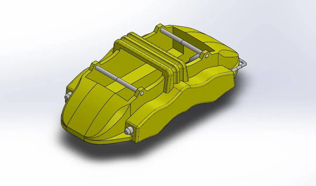
FIG 8.2
3 - Rim
For this we have used REVEOLVE, EXTRUDED CUT, FILLET, LOFT, CUT WITH BODIES, COMBINE. MOVE/COPY Bodies. Consider the image below.
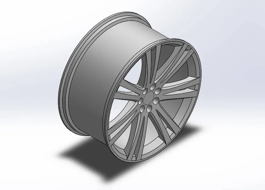
FIG - 8.3
4 - Disk
This part is pretty easy as well, we used EXTRUDE, EXTRUDE CUT, REVOLVE, PATTERN. Consider the image below .
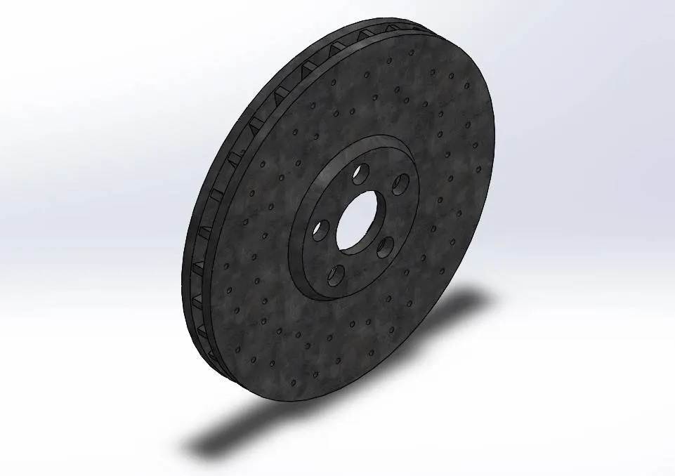
FIG - 8.4
NOTE - a. These part are for Front, the EXACT SAME are made for REAR but with change in RIM and TYRE Size.
b. After making all the parts we have assembled it together. Saperately.
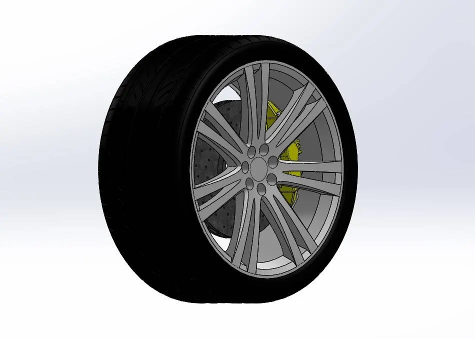
FIG - 9.5
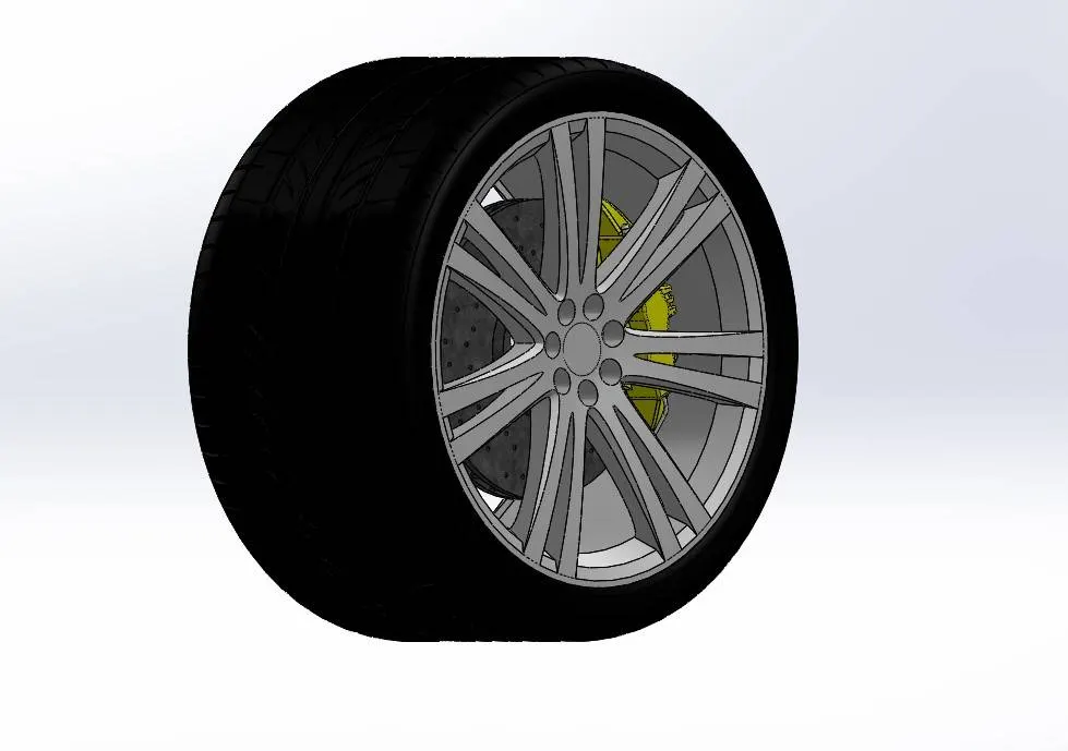
FIG - 8.6
09 - Emblem
For this we have used EXTRUDE, THICKNED, EXTRUDE CUT, COMBINE, MIRROR and FLEX (this feature allows us to twist/flex the body at an angle)
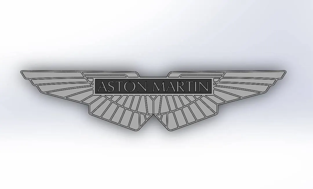
Now since all models are completed we will move to the ASSEMBLY. We all the Parts shown above.
For the Assembly we have used general mates no high skill is used in here, all the planes are referenced to the main ORIGIN PLANES.
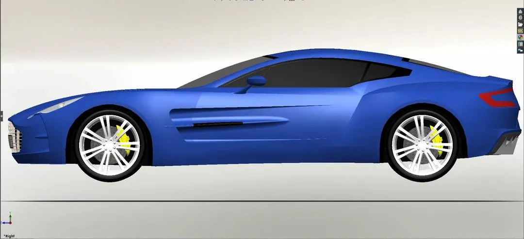
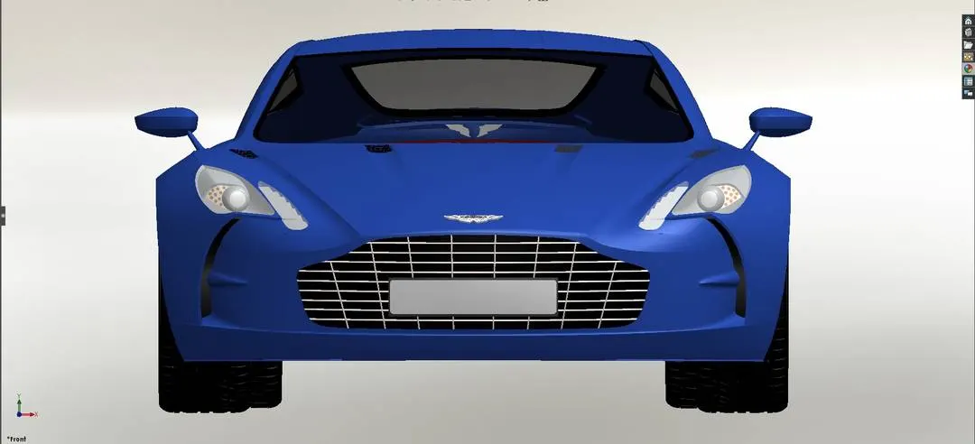
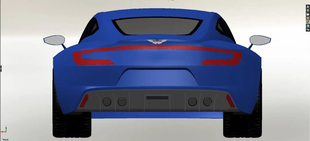
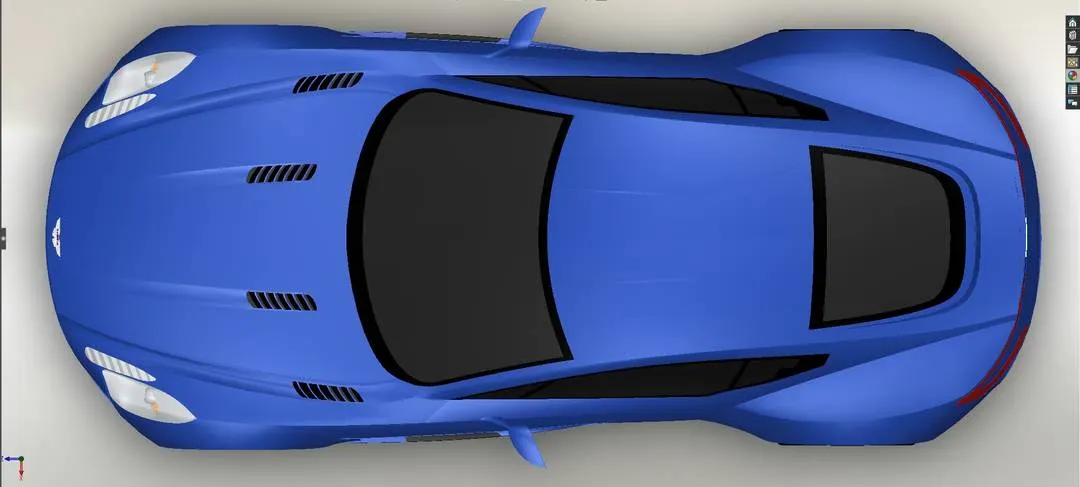
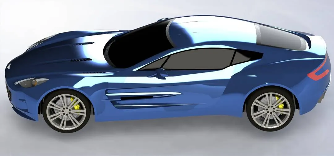
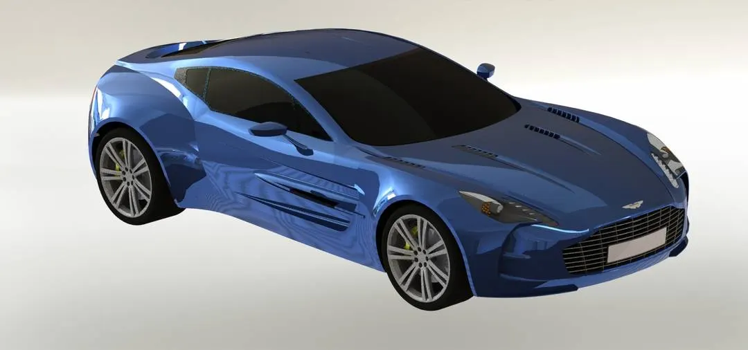
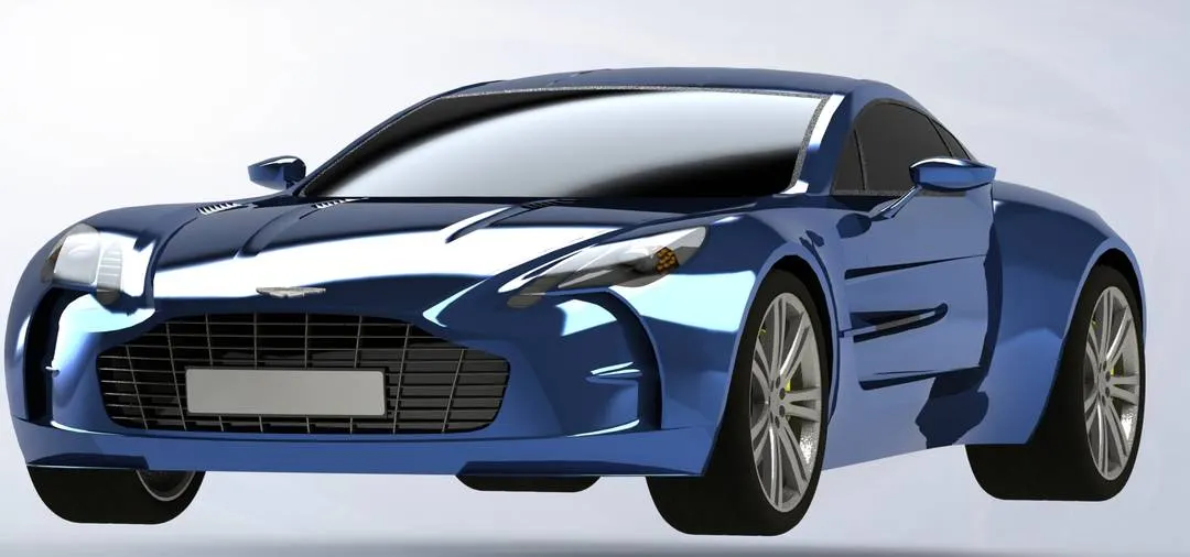
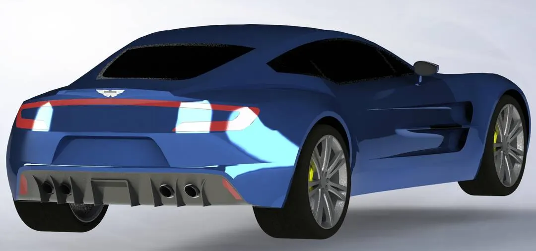
Consider the final images of the Assembly as well as the Rendered images.
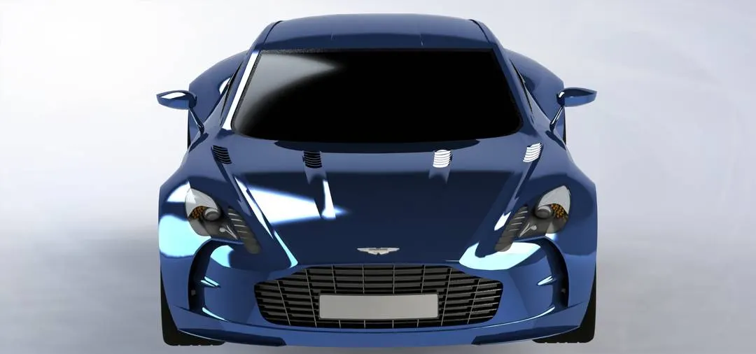
Conclusion -
After finishing this project we have learnt so many features which we do not use on a day to day basis but are important when needed because there are no alternatives, also, we have covered almost all the surface tools. We learnt how to use surface tools in solid modelling to achieve some parts, which are actually thought or not possible with solid modelling tools only. More over part handling ability was significantly increased since we have manipulated these may parrts and at the end we assembled all and as a reward we got this absolutely stunning piece of Engineering.