Case study on 3 way cat DOC DPF and SCR systems - IC-Engine Calibration Using GT-Power and GT-Suite.
IC-Engine Calibration Using GT-Power and GT-Suite
Assingment:9 (Case study on 3 way cat DOC DPF and SCR systems )
Objectives:
- To explore the examples provided below and write a detailed report.
Detailed SI engine+aftertreatment
Detailed CI engine+aftertreatment
- Comparing results of all cases.
Description:
Three-Way Catalytic Converters:
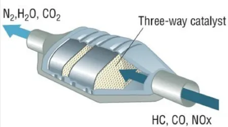
It allows reduction of NOx(nitrogen oxides) to N2(nitrogen) and O2(oxygen).
Allows oxidation of CO(carbon monoxide) to CO2(carbon dioxide).
Allows oxidation of HC (unburt hydrocarbons) to CO2(carbon dioxide) and H20(water).
The engine exhaust gases contains hazardous substances that cause damage to environment. These include the oxides of nitrogen, hydrocarbons, and carbonmonoxide.This three way converter converts them into carbon dioxide, water, and nitrogen.The 3-way catalytic converter consists of two different catalysts i.e. reduction catalyst & oxidation catalyst. The oxidation catalyst is made of palladium and platinum where as reduction catalyst is made of rhodium and platnium. oxidation catalyst is made of palladium and platinum and reduction catalyst is made of rhodium and platnium.
Diesel Oxidation Catalyst:
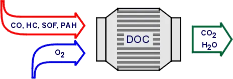
DOC are catalytic converters designed specially for diesel engines equipment to reduce Carbon Mooxide(CO), Hydrocarbons (HC) and Particulate Matter(PM) emissions. The device uses O2 in the exhaust gas stream to convert the carbon monoxide to carbon dioxide. These converters perform at 90% efficiency. A minimum exhaust temperature of 200deg is necessary for the catalyst to light off.
Catalyst Used:- Palladiumis the catalyst material.
Diesel Particulate Filter:
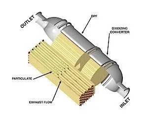
DPF operates by trapping soot particles from the engine exhaust, preventing them from reaching the atmosphere.The particulate filter is designed to trap and retain the solid particles untill the particles can be oxidized in the DPF itself through the process called regeneration. Te soot containing the exhaust to flow through the porousfilter walls.While the gas flows through the walls, soot particles are trapped within the filter pores. The honey comb design of the filter provides a large filteration area while minimizing the pressure losses. Ceramic materials(like silicon carbide) are widely used for particulate filters, they provide good thermal durability.
Selective Catalytic Reduction(SCR):
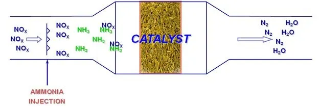
SCR is a means of converting nitrogen oxides (NOx)by means of the catalyst into Nitrogen(N2) and Water(H2O). We inject Ammoniato a stream of exhaust gas and is observed onto a catalyst. When the Urea comes in contact with the hot exhaust , it converts into Ammonia gases then the ammonia gas reacts with the exhaust gases in presence of catalyst to form N2 and H2O. The efficiency of the catalytic reduction depends on various factors like, dosage of the reducing agent, the volume of catalyst elements and the exhaust gas temperatures.
1. Detailed_CI_Engine_Aftertreatment:-
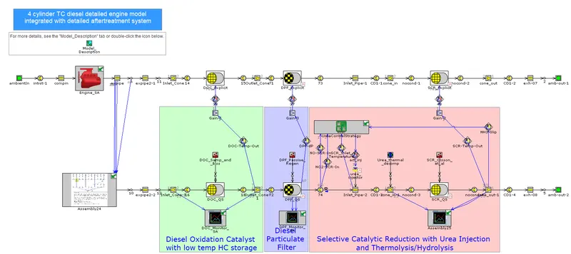
This model shows the detailed engine and detailed aftertreatment system running one steady state operating point.The comolete engine model is taken from Diesel_WG_Controller example from engine performance directory. The aftertreatment system is the combination of the DOC_Sampara_and_Bissett and SCR_Fe_Zeolite example models along with DPF setup for passive generation, same urea injection system used in EngineState_Vehicle_Aftertreatment_NEDC example model.
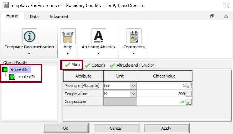
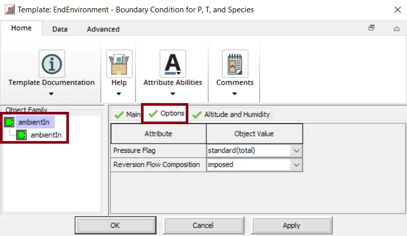
The 'EndEnvironment(inlet)' template describes the boundary conditions of pressure, temperature,and composition parameters. Here we specify the pressure, temperature and composition as per the requirement. In this case the composition considered is choosen as air.
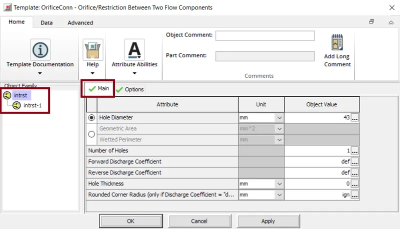
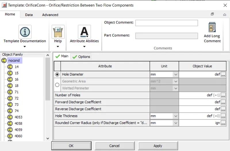
The orifice model template is used to define the diameter or area and discharge coefficients which calculate the mass of the flow rate between the adjacent flow volumes. Here the hole diameter is set to 43mm. Number of holes considered is 1.
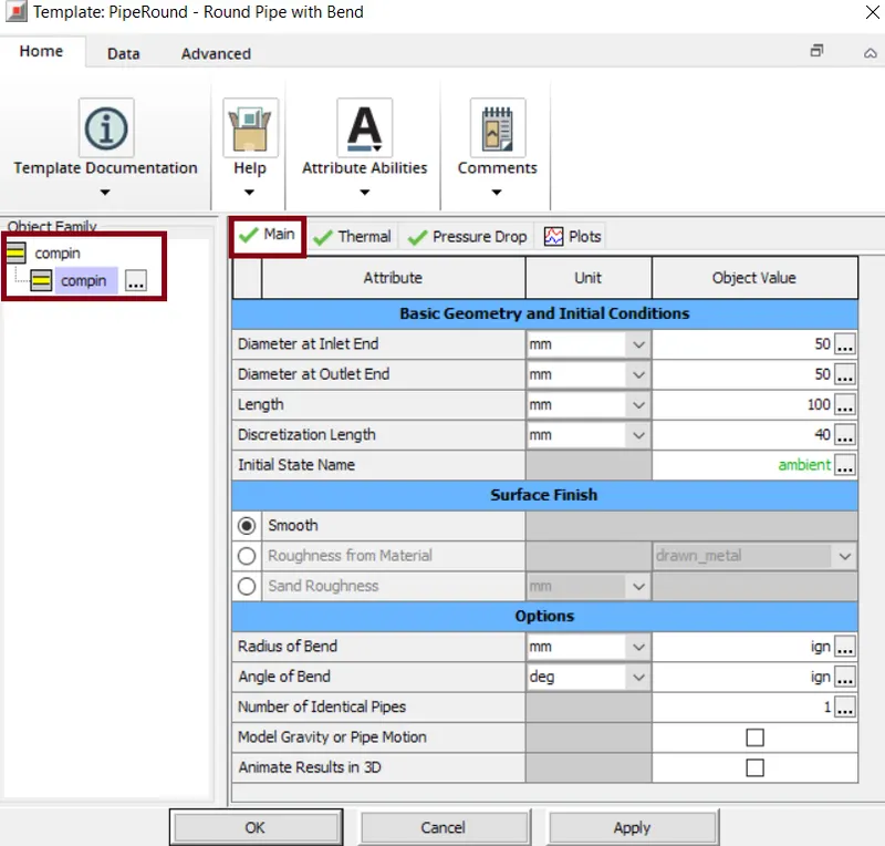
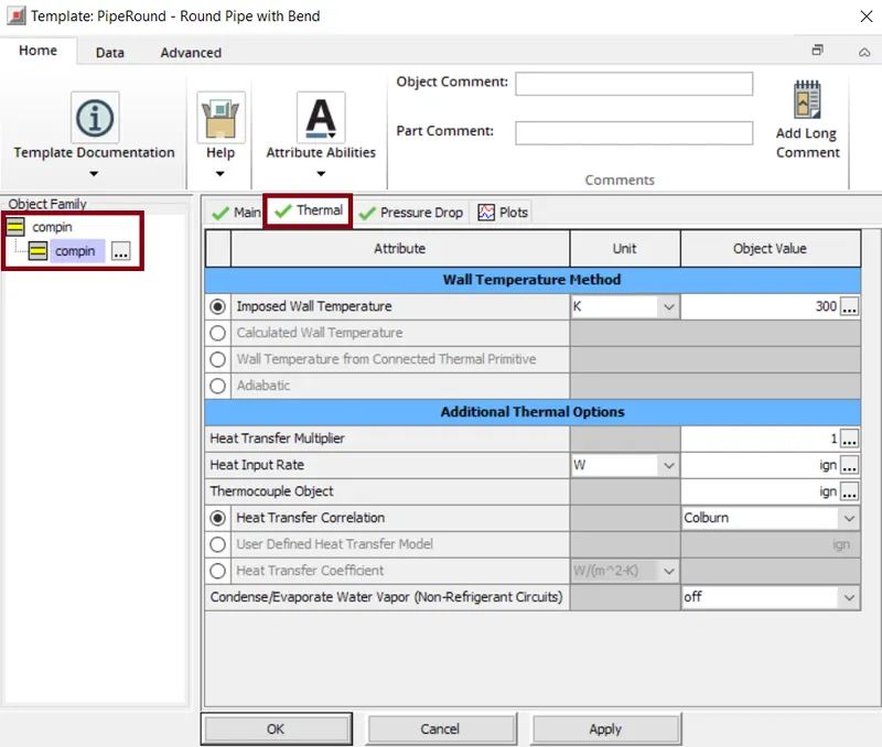
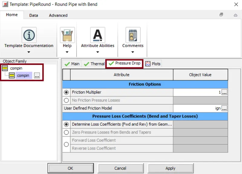
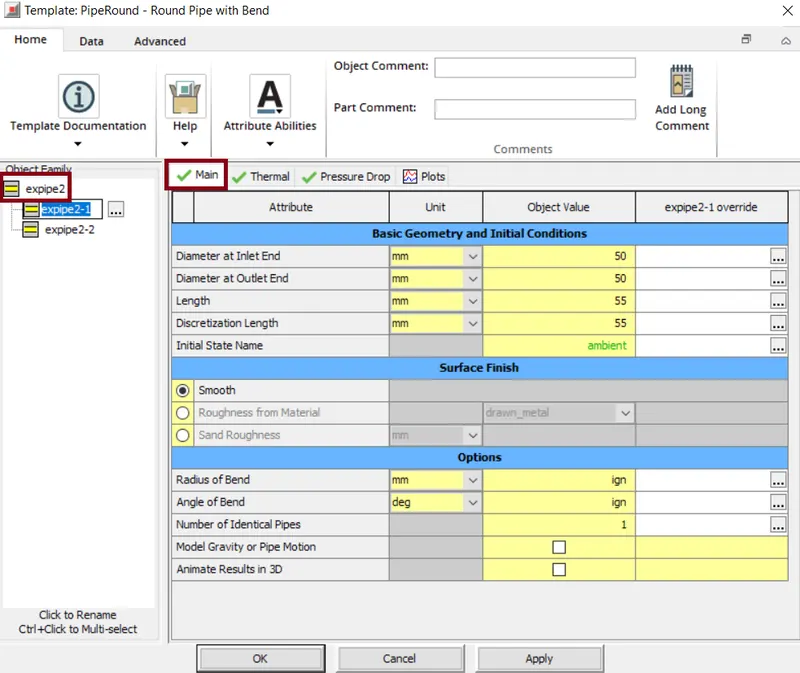
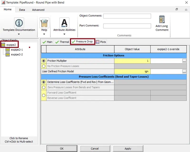
The PipeRound template model pipes that have a round cross-section and an optional bend.The diameter of inlet and outlet pipe is specified.Also the length , discretization length also mentioned . Along with this the thermal properties, the imposed -wall temperatures is specified and the heat transfer correlation used is 'Colburn'. The pressure drop value is also mentioned.
Engine Model:-
Engine:
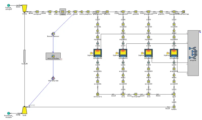
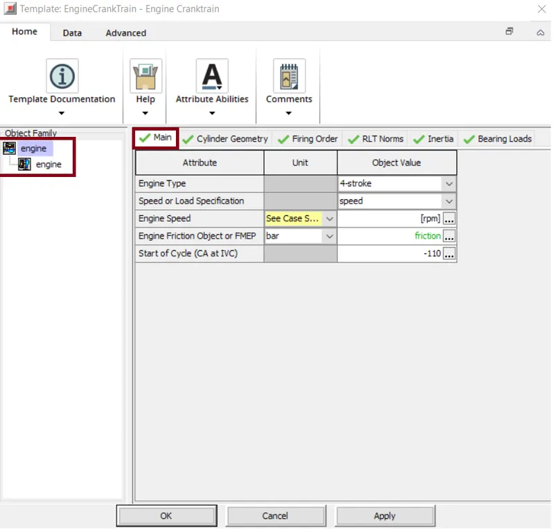
The engine template specifies teh attributes of the 'EngneCrankTrain' part which is used to model the kinematics and the dynamics of common reciprocating IC engine cranktrain. Initially Engine type i.e 2-stroke or 4-stroke should be selected. Type of load is also specified like speed or load to be applied. Along with this the speed of the engine is also mentioned. The start of the cycle is important as the engine crankshaft starts rotating i.e. start of cycle is at -110.
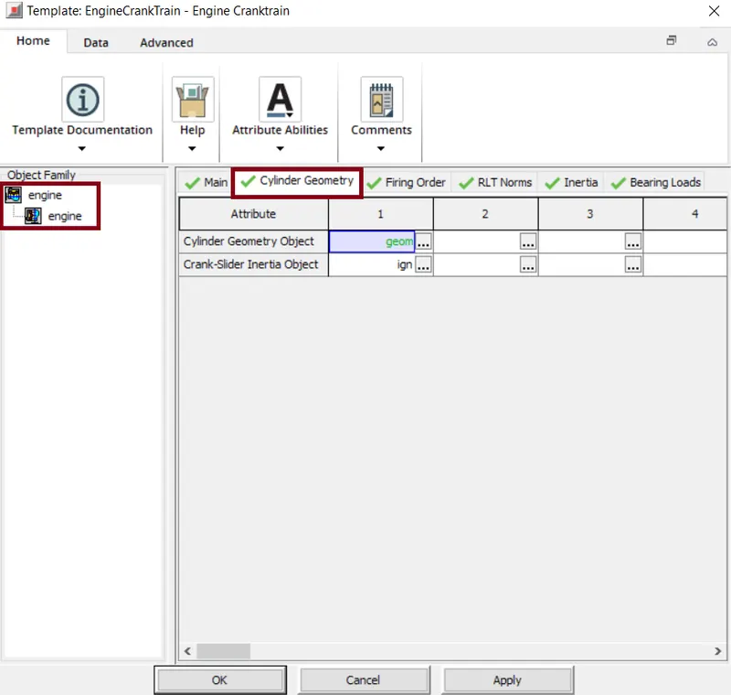
The cylinder geometry details are mentioned.Here the cylinder geometry object is completely defined in "geom" window.
Here the engine bore, stroke, connecting rod length, compression ratio is defined here so that the engine is prepared as required. Also the piston to crankoffset is set here.
Bore=100mm, Stroke=110mm, Connecting rod length=152mm, compression ratio= 18 & TDC clerance height =1mm.

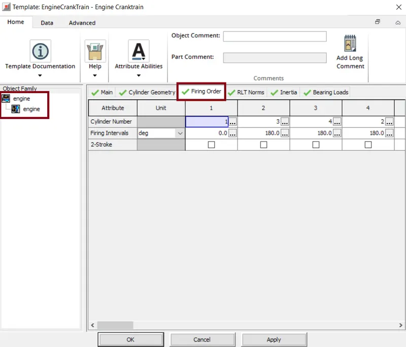
As this is a 4-cylinder engine the firing order given is 1-3-4-2. In this case we have 4-cylinders, so the firing interval starts with 0 deg for the first cylinder and for the rest of the cylinders the firing interval is 180deg.
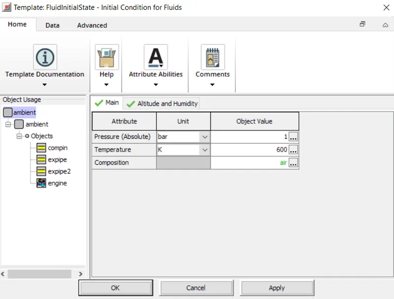
In the RLT Norms the reference state for the Volumetric efficiency is provided.The Fluid_Initial_State reference object that is used to provide the reference density for the calculation of the volumetric efficiency RLT variables in 'EngCylinder' - "ambient". Here we specify the temperature, initial pressure and the fluid properties in the flow components. And rest of the things are left unchanged.
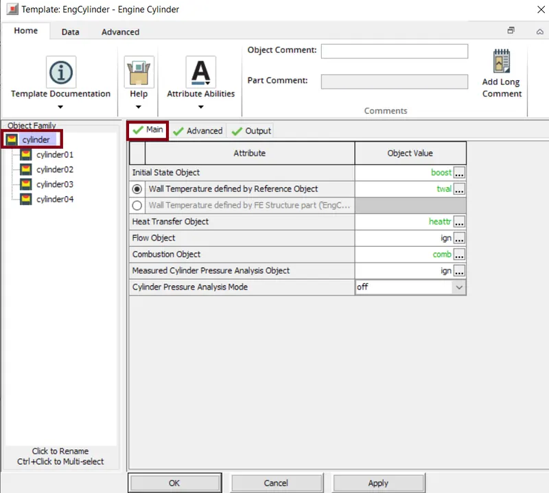
The cylinder template is used to specify the attributes of the engine cylinders. Various parameters like wall temperature, heat transfer object, combustion object, flow object are specified using a individual reference object.
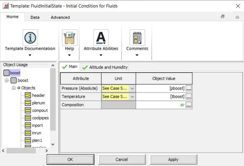
This object specifies the initial pressure, temperature and the fluid properties in the flow components and can be reffered by any flow component with the volume parameter. Here the pressure and temperature are specified in case-setup as we are doing them for multiple cases.
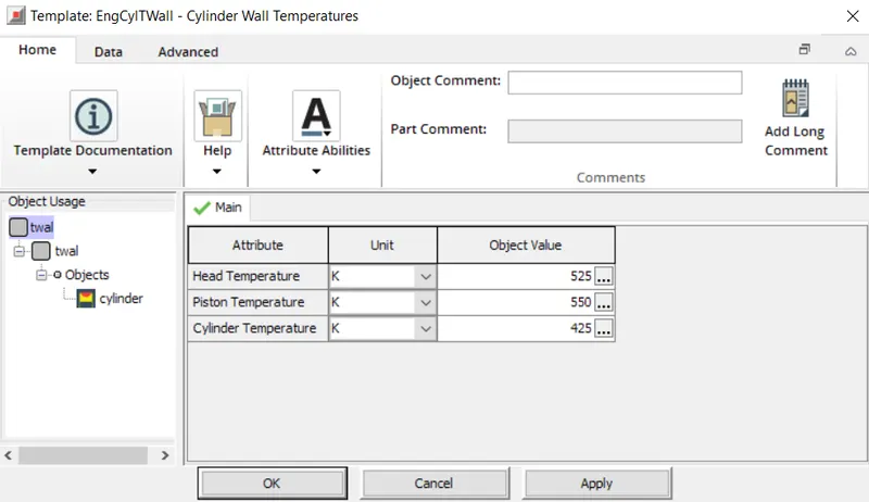
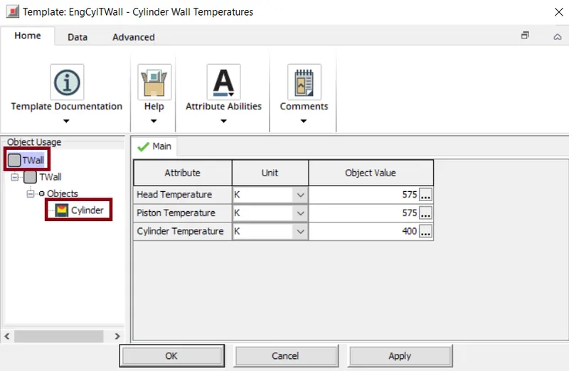
The wall temperature refers to the cylinders wall temperature. This template is called by the EngineCylinder , PistonCylinder or the EngineCrankcase objects to specify the in cylinder chamber surface temperatures for heat transfer calculations.
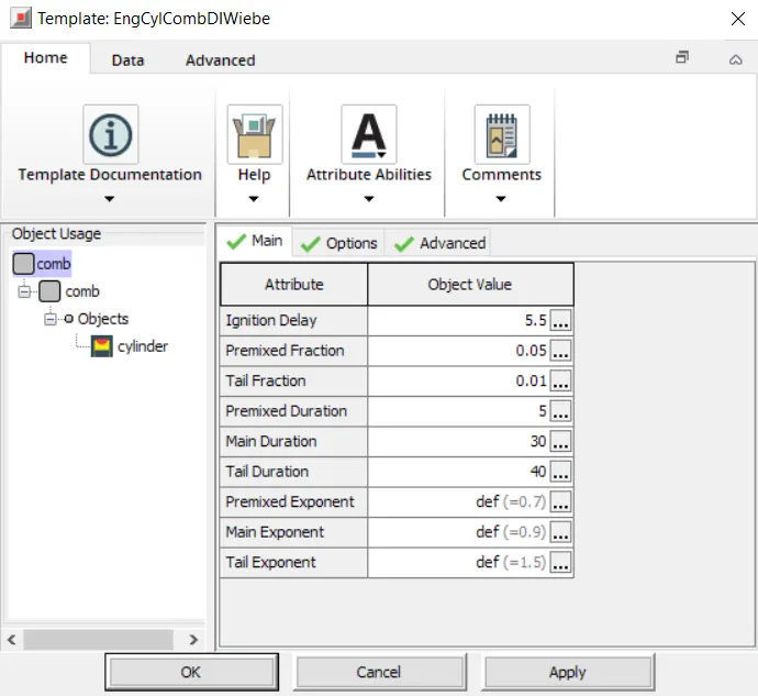
The combustion object template imposes the combustion burn rate for direct injection, compression ignition engines using three term wiebe function.
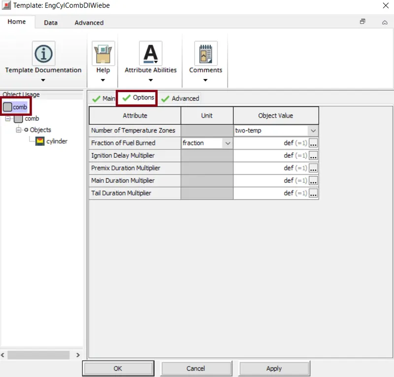
Here the object predicts the NOx formation during the combustion and the extended Zeldovich mechanism is used to model the total NOx in the cylinder.
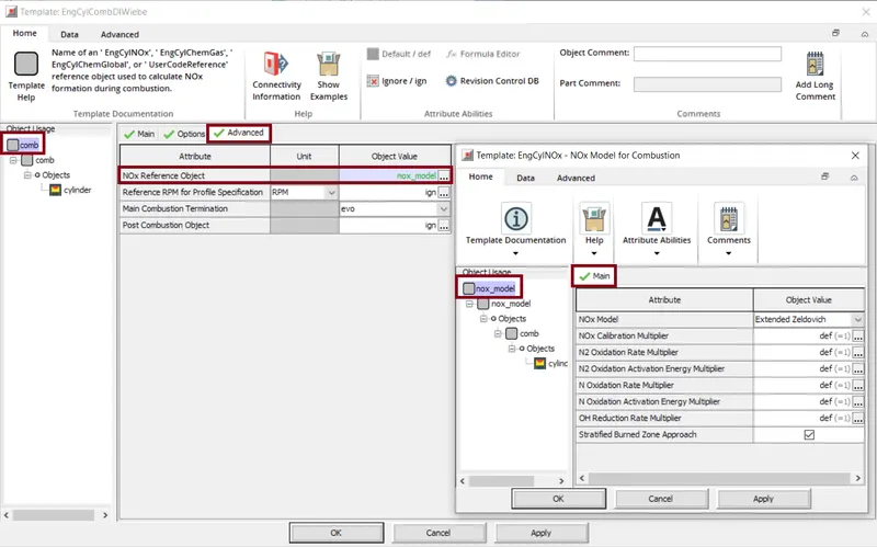
Also, we can specify the EngCylEmisMaps as the reference object which allows a user to impose the emissions species as a function of multiple independent variables. The Emission Map Object we can mention the different pollutants i.e. the pollution object(soot), units of the particular pollutant object considered, also the quantity is specified here.
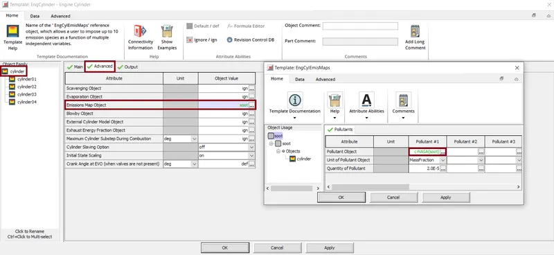
The "c-NASA(soot) object" shows the necessary properties of the soot particles i.e. the unburnt carbon particles.
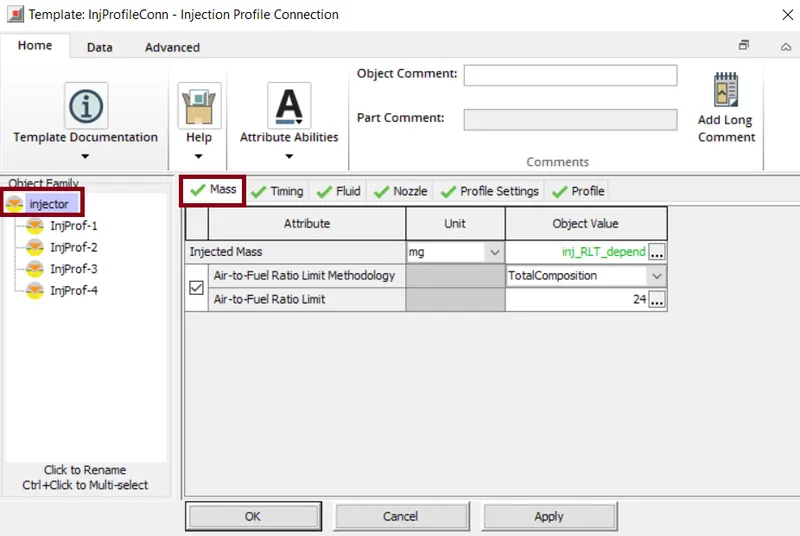
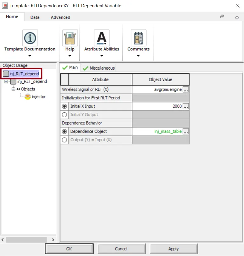
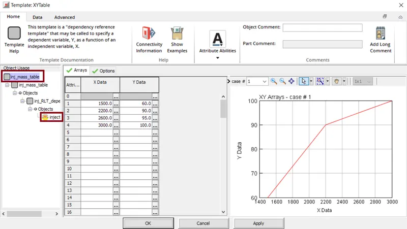
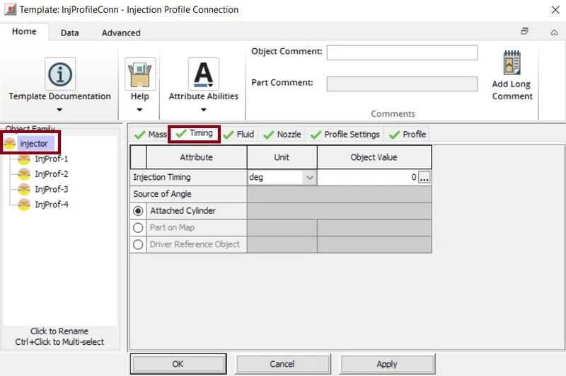
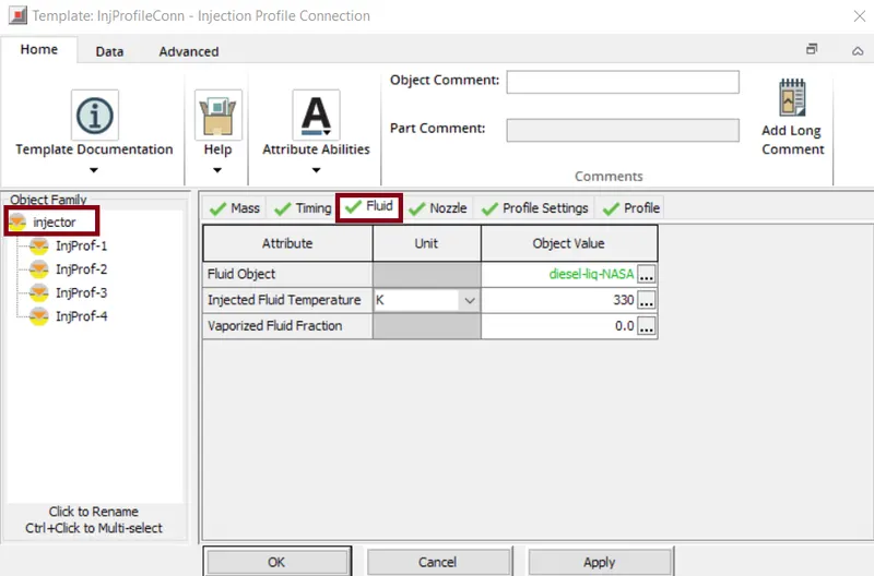
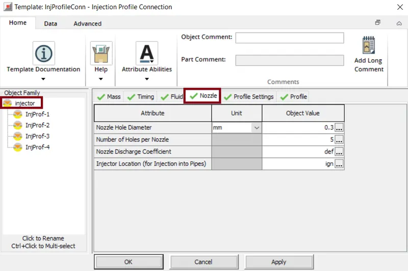
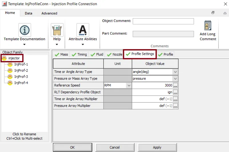
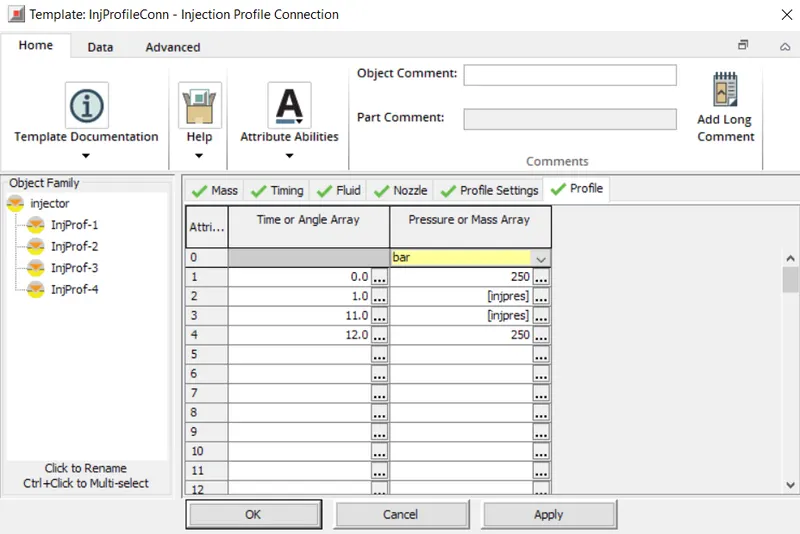
The fuel injection connection allows for the injection of a periodic mass flow rate or pressure profile.Here all the parameters required to operate the injectors are specified.
inj_mass_table:
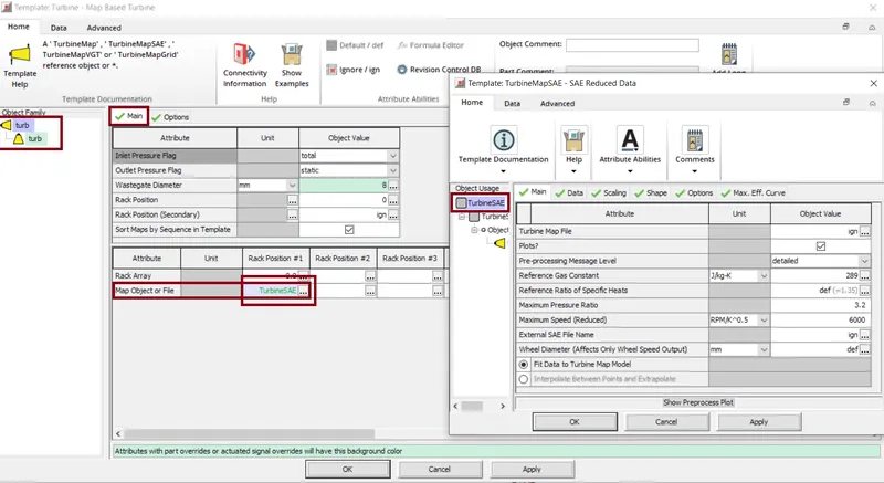
The part "turb" is a template that models a turbine with gas flowing through it. We have varaious attributes that describe a turbine. Here the attributes are used to indicate the type of Inlet/outlet pressure measurement used when creating the map.
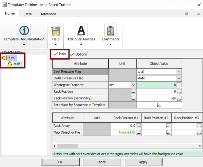
In this case we use a 'Turbine Map' as a reference Map object. This template takes turbine ma data, supplied by the turbine manufacturer, fits it to the equation that represents the data.
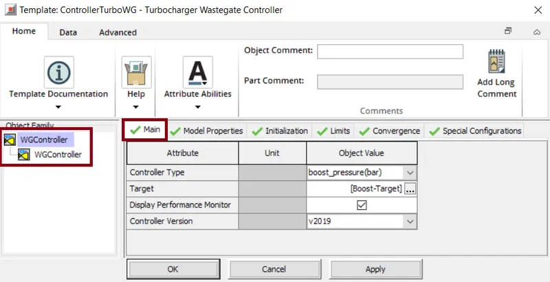
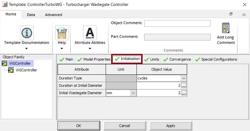
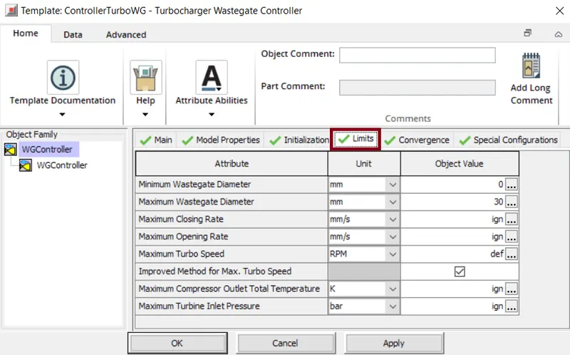
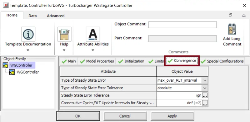
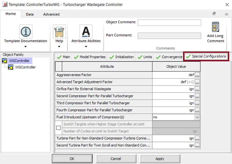
The turbo charger "Wastegate controller" template is generally used to target various engine performance parameters in the turbocharged applications.

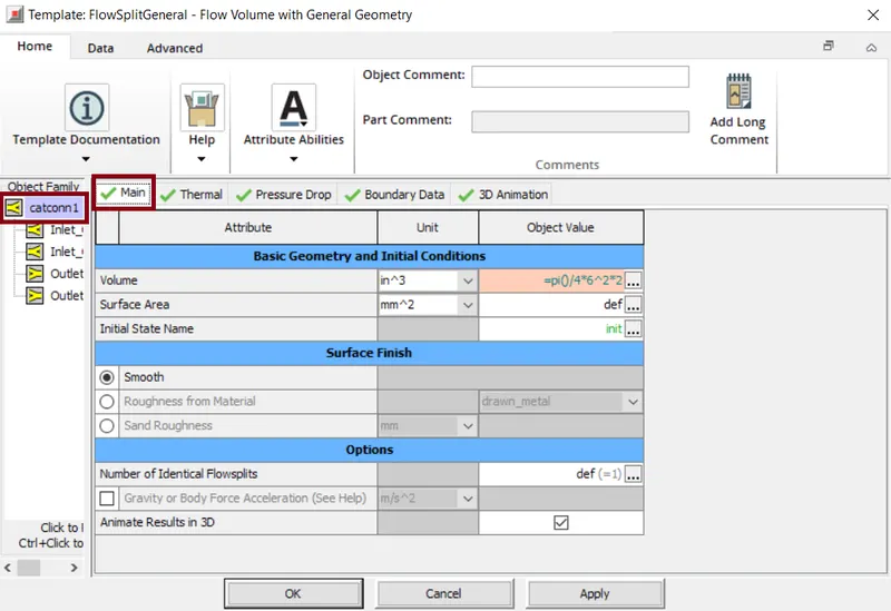
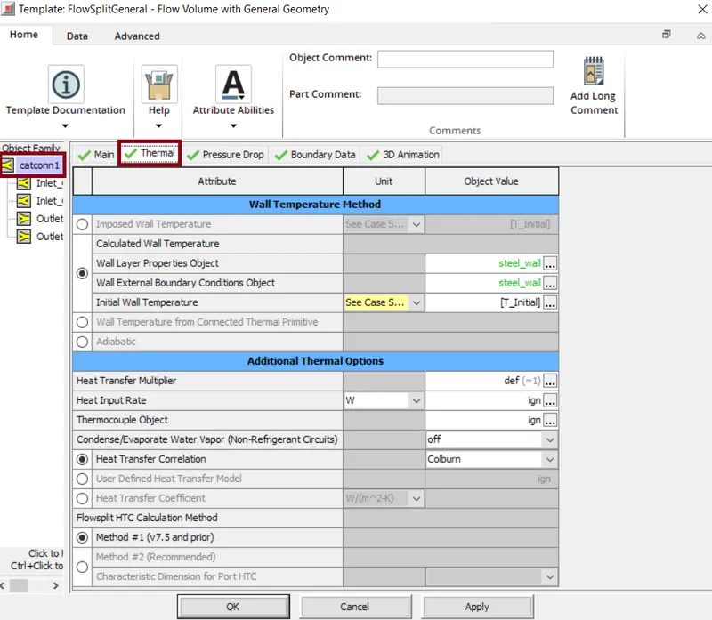
The FlowSplitGeneral template generallyy used to specify the flow volume parameters as well as the general geometry parameters.
Exhaust Aftertreatment:
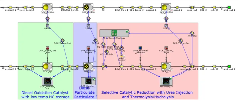
From the above model we can see that there are two sets of same exhaust model. The one which is connected to the engine (top) uses the explicit flow solver to model the flow inside the exhaust components. And the other uses the quasi-steady flow solver inorder to model the exhaust system and while modelling it considers the chemical reactions taking place in various subcomponents like DPF, SCR, DOC etc.

The PipeRound template model pipes that have a round cross-section and an optional bend.The diameter of inlet and outlet pipe is specified.Also the length , discretization length also mentioned . Along with this the thermal properties, the imposed -wall temperatures is specified and the heat transfer correlation used is 'Colburn'. The pressure drop value is also mentioned.
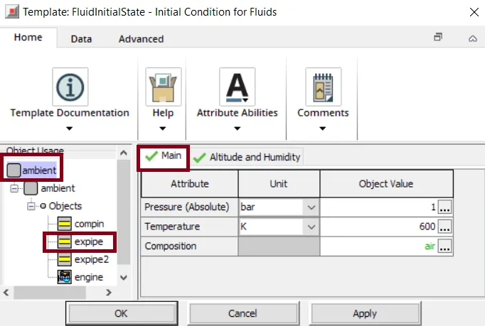
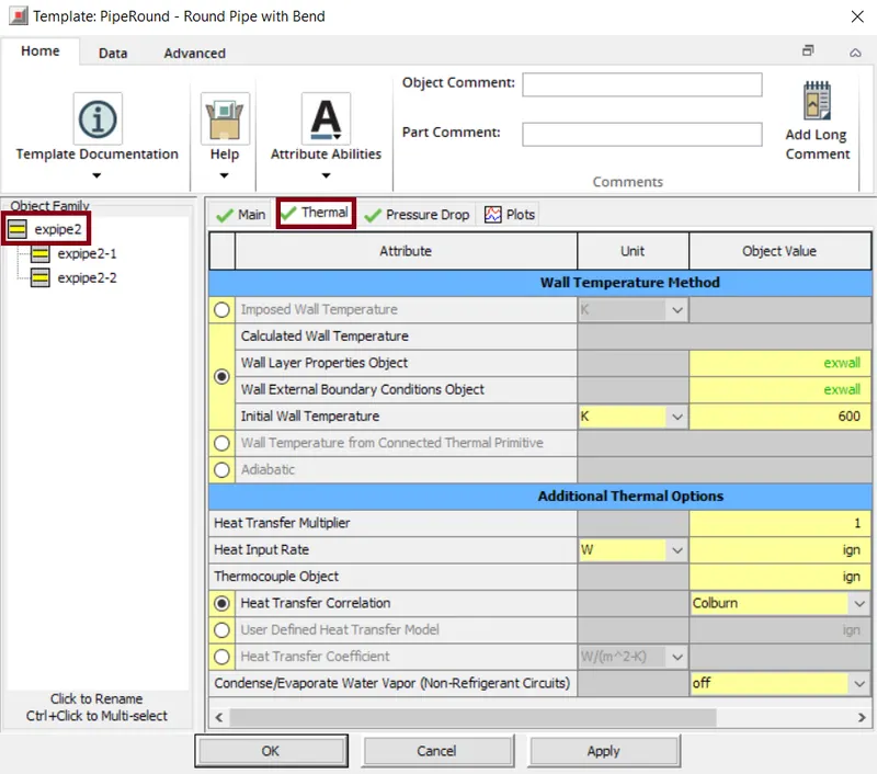
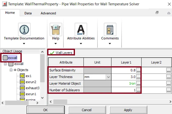
In the wall temperature method, the 'WallThermalProperty' reference object defines the thermal properties of the wall like thickness, kind of material, emissivity etc.
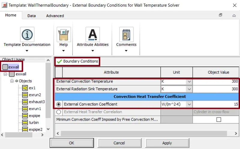
Similarly, the 'WallThermalBoundary' reference object defines the boundary conditions of the wall like ambient temperatures, external convections etc.
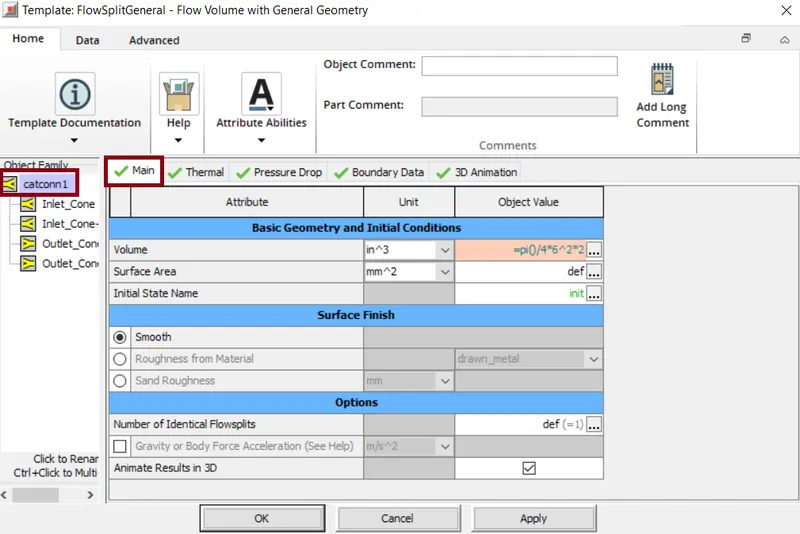
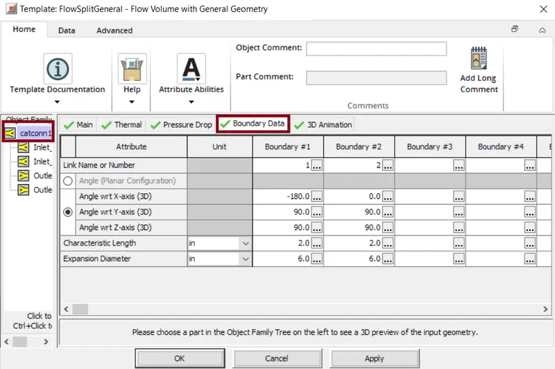
Next, a 'FlowSplitGeneral' template is used to model any arbitrarily shaped flow volume. Here the basic geometry details and the initial conditions are specified. Also the type of surface finish is also mentioned.
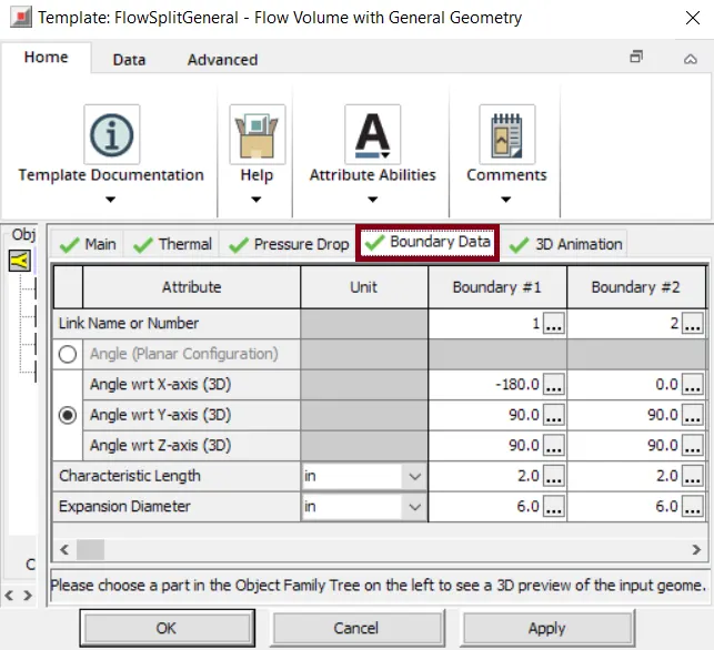
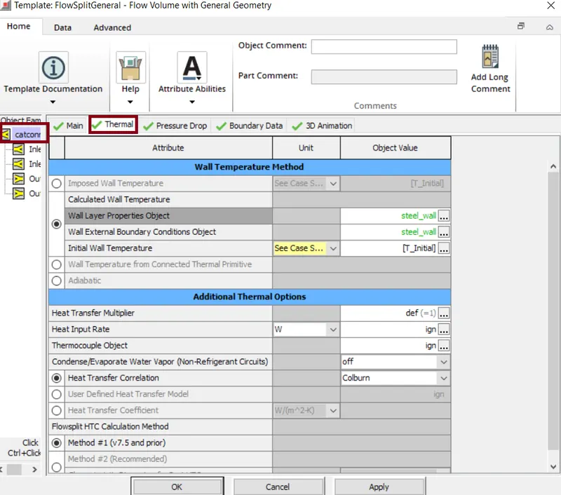
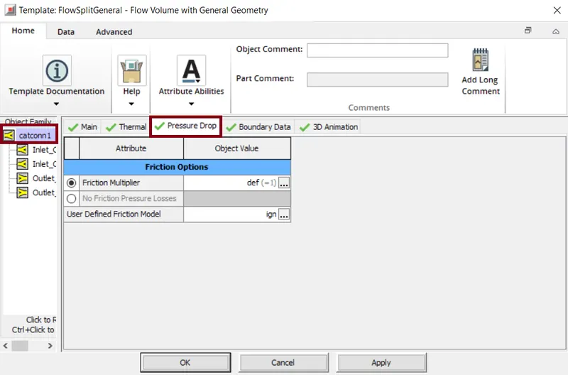
Similary the thermal properties in Wall Temperature Method are mentioned. Along with this the thermal properties, the imposed -wall temperatures is specified and the heat transfer correlation used is 'Colburn'. The pressure drop value is also mentioned. To this the boundary datat is also considered along with the respective axis.
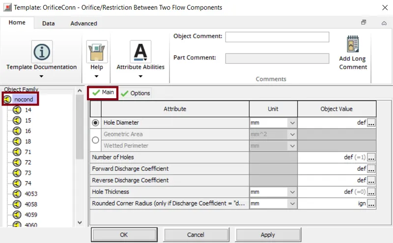
The oriffice connection template models an orifice, here we can define diameteror area and the discharge coefficients which calculates the mass flow rate between the adjacent flow volumes.
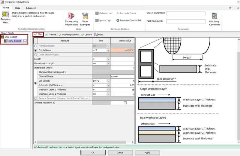
Diesel Oxidation Catalyst (DOC_Explicit)
Here we provide various parameters that are related to catalyst substrate i.e. the fontal area(in^2)= =pi()/4*6^2, length of the substrate channels=6inches, discretization length=55mm and the initial state object is provided with reference object describing the initial conditions of the gas inside the catalyst.
In thermal properties,we impose a temperature that represent the temperature of the wall surface directly in contact with the fluid.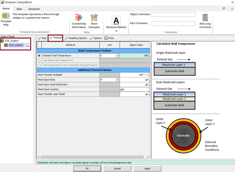
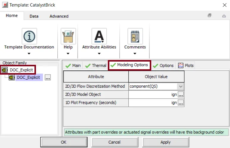
In the modelling part, we select the kind of modeling i.e 2D/3D. Also for the flow discretization method,the component(QS) indicates that a single catalyst will be used for the solution.
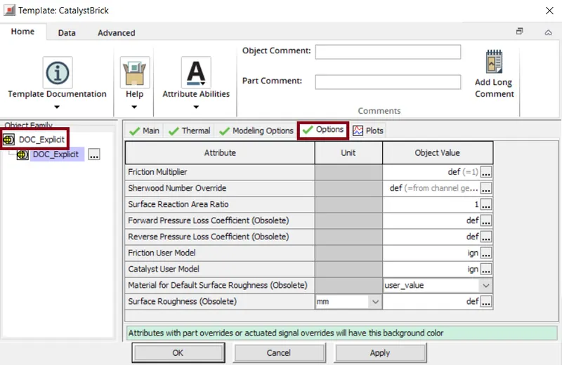
The oriffice connection template models an orifice, here we can define diameter or area and the discharge coefficients which calculates the mass flow rate between the adjacent flow volumes.
Diesel particulate filter (DPF_Explicit)
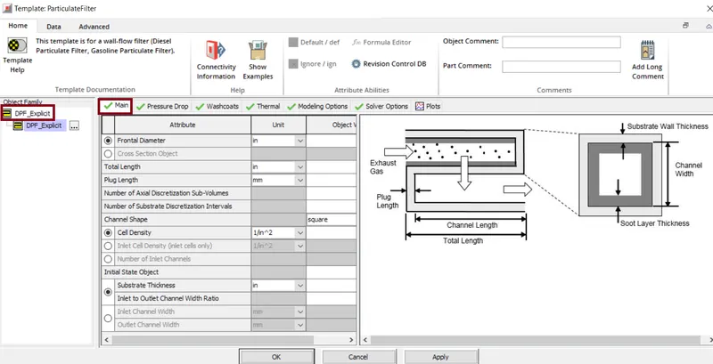
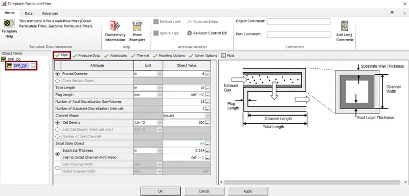
The particulateFilter template is for a wall-flow filter i.e. Diesel particulate filter, Gasoline particulate filter etc. Here we define the basic parameters like diameter, length, channel size, etc. Also the total cell density and the initial state object is defined. The FluidInitialState template specifies the initial pressure, temperature and all other fluid properties in the flow components also can be reffered by any flow component with the volume.
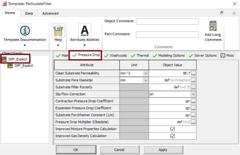
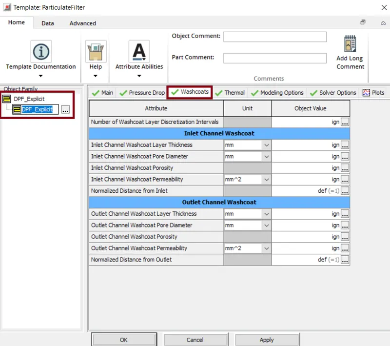
Here in this template we define various parameters like the number of washcoat layer discrerization interbvals to be used for DPF model. Along with this also we define the parameters for both inlet/outlet channel Washcoat.
In the particulate filter the thermal properties play an important role. Here we impose a temperature that represents the temperature of the wall surface directly in contact with the fluid.
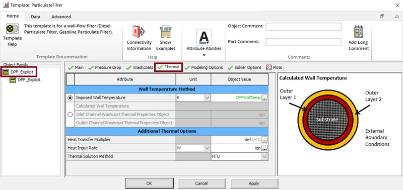
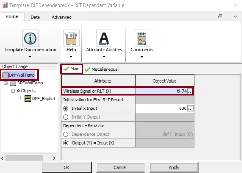
In this case we select "Imposed Wall Temerature=DPFWallTemp". The DPFWallTemp is defined by the RLTDDependenceXY object.
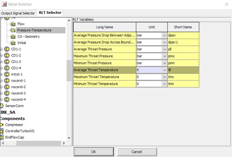
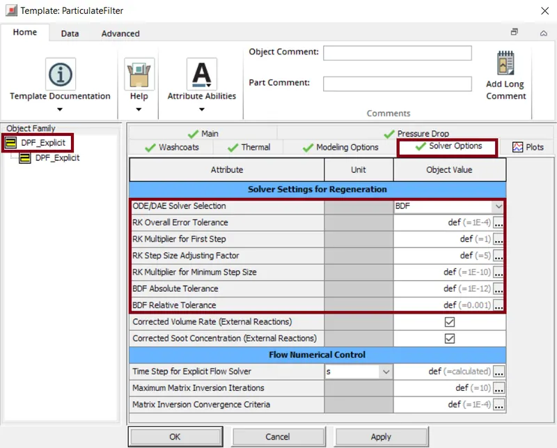
For this object the solver options helps to clearly specify the solver settings for the regenerationalong with the flow numerical control calculations. Here we have two solver methods i.e. ODE/DAE, for this BDF (Backward Differential Formulations)selected for the filter regeneration applications. The Adaptive RK(Adaptive Runge-kutta method) is used to solve the initial valuse problems of differential equations. This method is generally used to construct high order accurate numerical method by functions itself without needing the high order derivatives of the functions. The time step for explicit flow solver is also provided.
Selective Catalytic Reduction (SCR_Explicit)
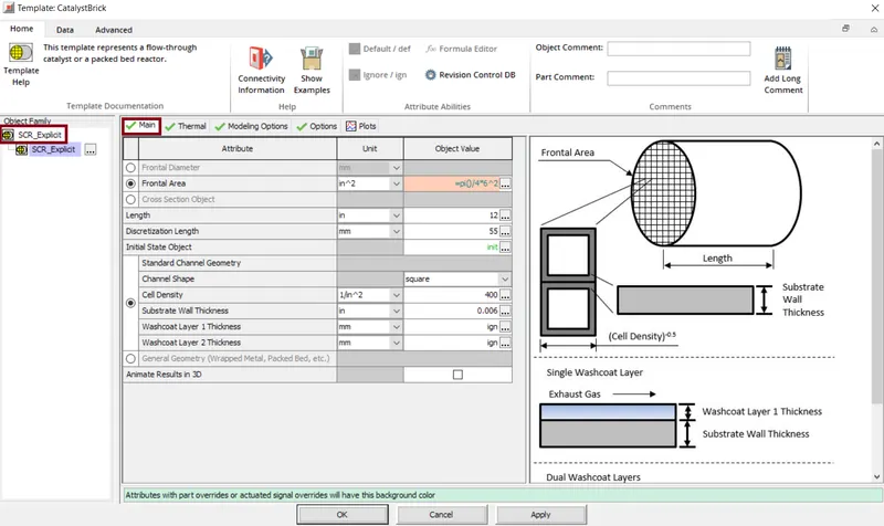
The CatalystBrick template helps to represent the flow through the catalyst.Here we provide various parameters that are related to catalyst substrate i.e. the fontal area(in^2)= =pi()/4*6^2, length of the substrate channels=12inches, discretization length=55mm and the initial state object is provided with reference object describing the initial conditions of the gas inside the catalyst.
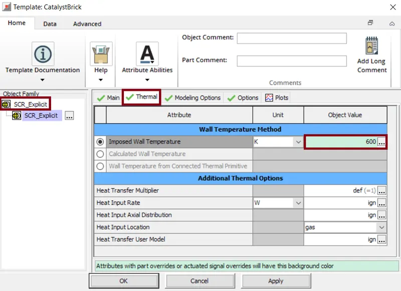
In thermal properties,we impose a temperature that represent the temperature of the wall surface directly in contact with the fluid.
In the modelling part, we select the kind of modeling i.e 2D/3D. Also for the flow discretization method,the component(QS) indicates that a single catalyst will be used for the solution.
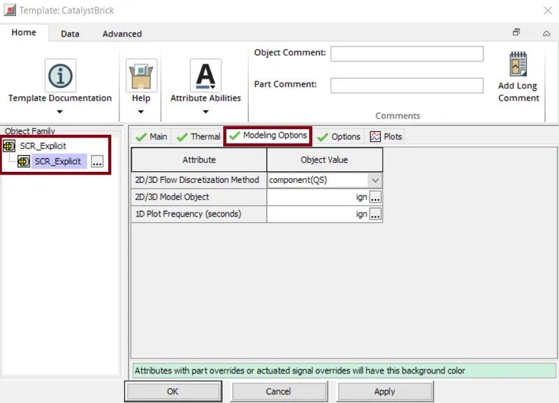
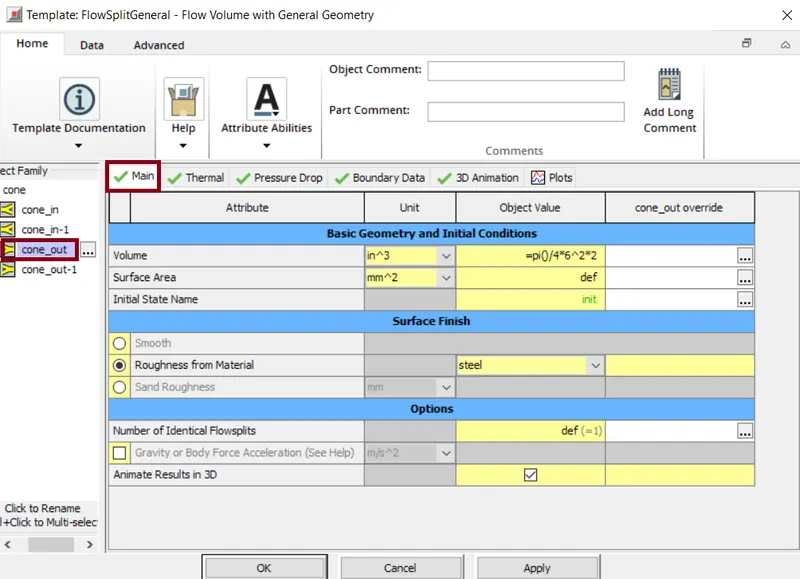
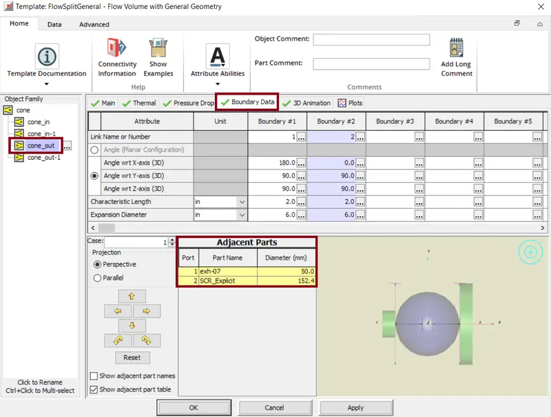
Next, a 'FlowSplitGeneral' template is used to model the arbitrarily shaped flow volume. Here the basic geometry details and the initial conditions are specified for the outlet.
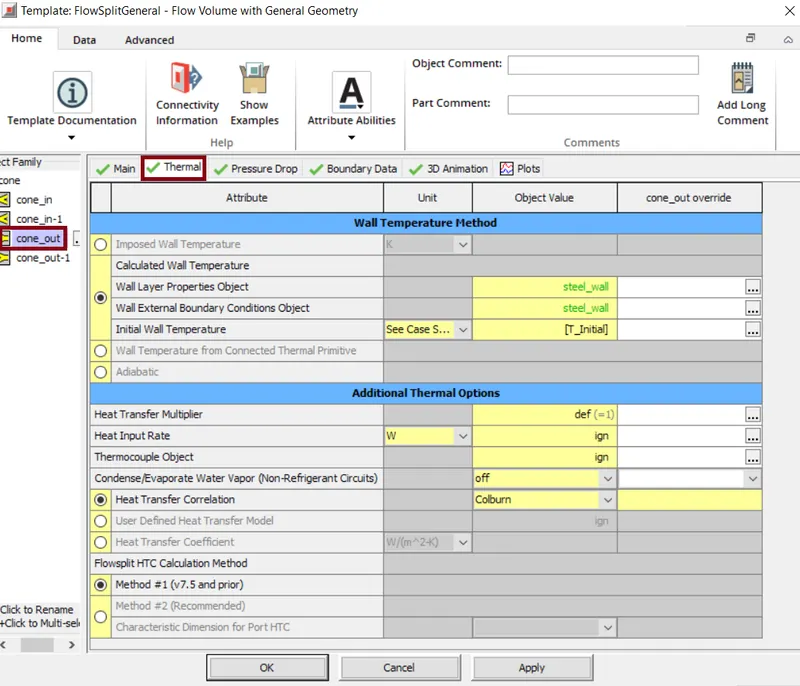
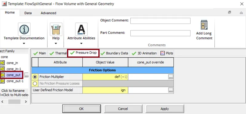
The thermal properties in Wall Temperature Method are mentioned. Along with this the thermal properties, the imposed -wall temperatures is specified and the heat transfer correlation used is 'Colburn'. The pressure drop value is also mentioned. To this the boundary data is also considered along with the respective axis. Also the ports names along with its diameter is specified.
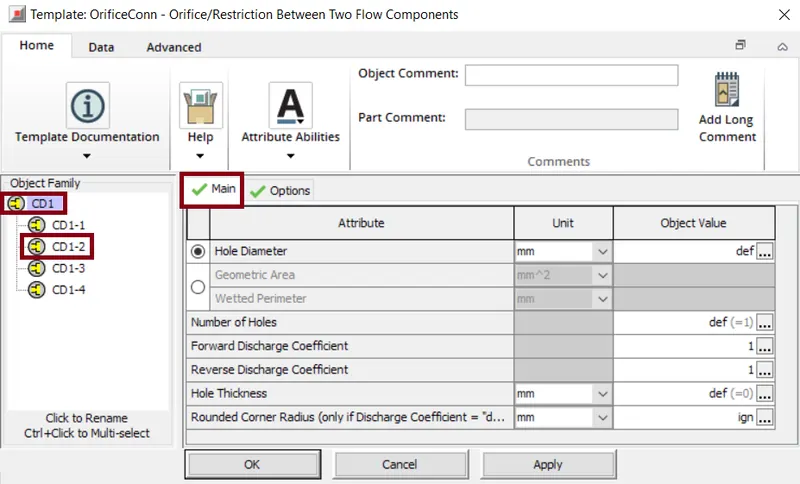
The orifice connection template is used to model an orifice, defined by diameter/area and discharge coefficients, which calculates the masss flow rate between the adjacent flow volumes.
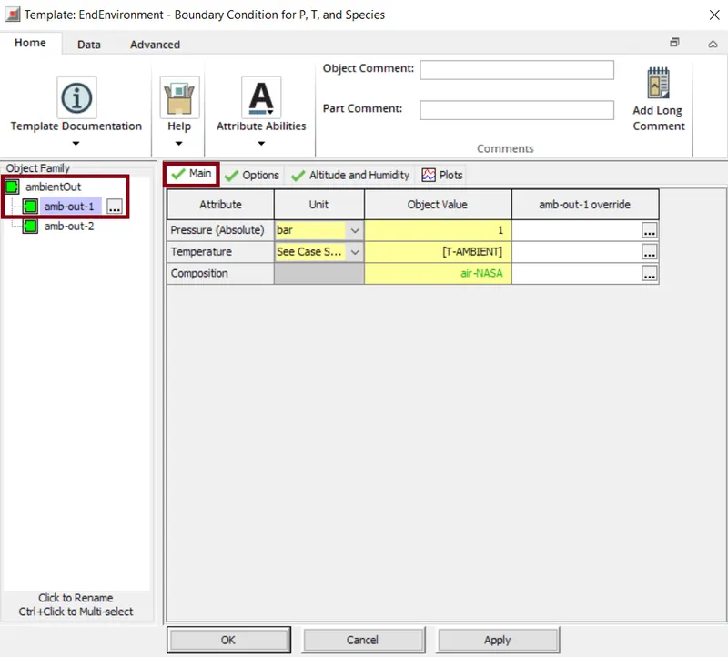
The 'EndEnvironment(outlet)' template describes the boundary conditions of pressure, temperature,and composition parameters. Here we specify the pressure, temperature and composition as per the requirement. In this case the composition considered is choosen as "air-NASA".
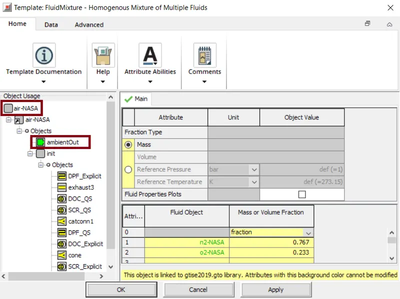
The fluid mixture template represents a homogeneous mixture of one or more liquids or gases or may be both. We specify the fluid object with mentioning the mass fraction/volume fraction value.
The second copy of exhaust system uses the Quasi-Steady Flow solver to model the exhaust system. The explicit and QS flow circuit settings are controlled under Home>RunSetup>FlowControl. In explicit solver the time step is automatically controlled but the quasi steady state circuit time step is user imposed.
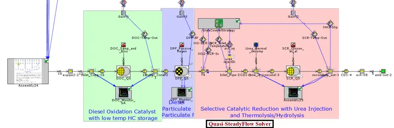
As the quasi state circuit is indipendent to the engine circuit, hence the the flow goes through the engine circuit. The bottom circuit only deals with the chemistry calculations. For the bottom circuit, the species are obtained from the engine-out i.e. it is indicated in "Assembly24". Here we get all the species that are comming out of the engine like soot, diesel vapour, total CO2, etc. We have a standard library from where we get all the species.
Once all the species are obtained we solve all the DOC,DPF and SCR.
Here in quasi steady state solver all the templates like PipeRound, FlowSplitGeneral, OrificeConnection, etc are set similar to the explict solver.
Diesel Oxidation Catalyst (DOC_QS)
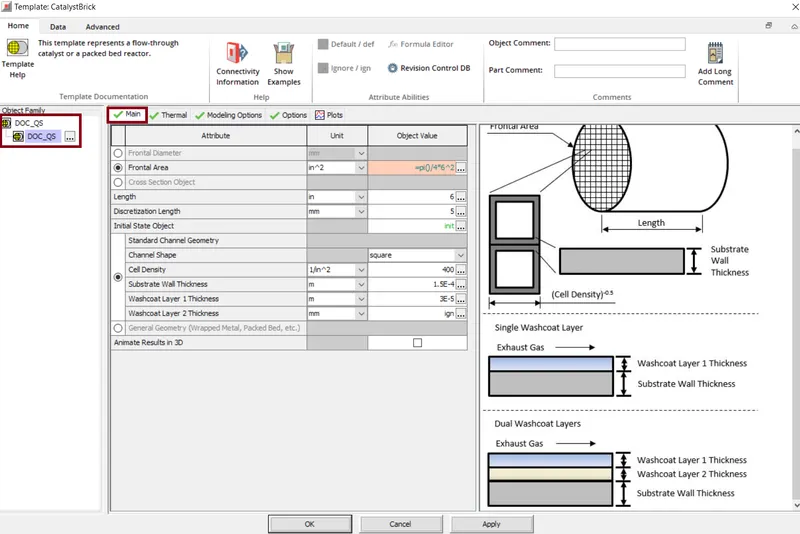
Here we provide various parameters that are related to catalyst substrate i.e. the fontal area(in^2)= =pi()/4*6^2, length of the substrate channels=6inches, discretization length=55mm and the initial state object is provided with reference object describing the initial conditions of the gas inside the catalyst.
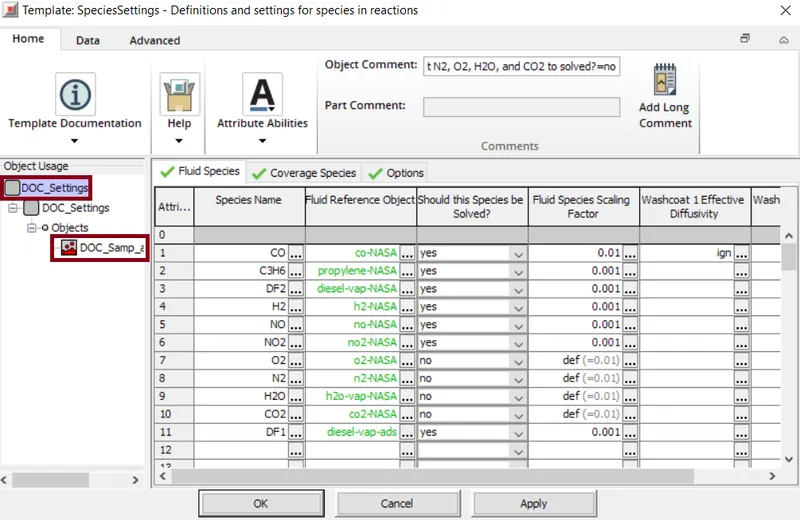
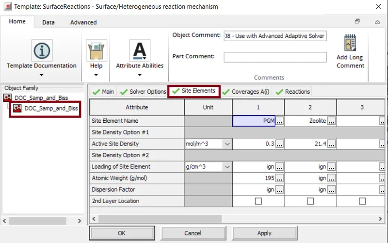
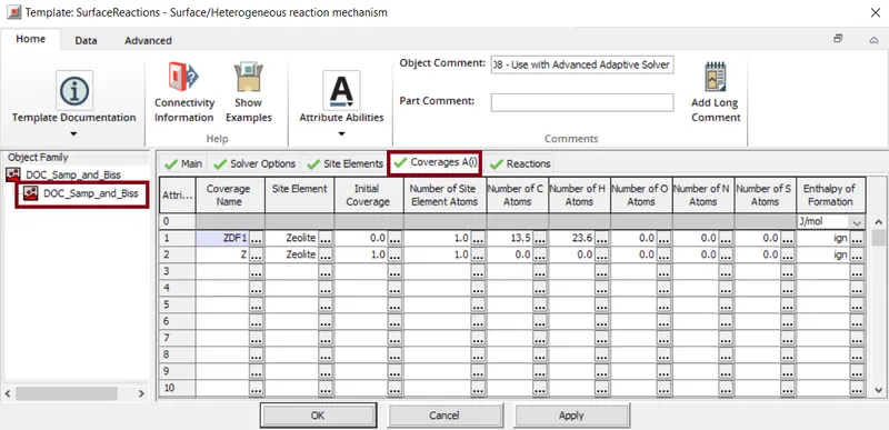
Here for the DOC_QS, a SurfaceReactions template is connected in which it specifies the catalytic surface reaction kinetics that require the modeling of storage.
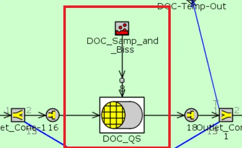
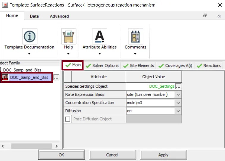
In speciesSettings object, reference object "DOC_Settings" is used for mapping the species specified in GaseousReactions, SurfaceReactions to the basic fluid objects.
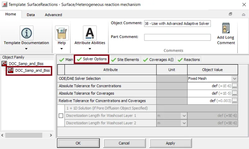
Here we can select the solver options i.e. ODE/DAE solver selection as 'Fixed Mesh'. Here we have option to select one among the following ODE/DAE solver methods.
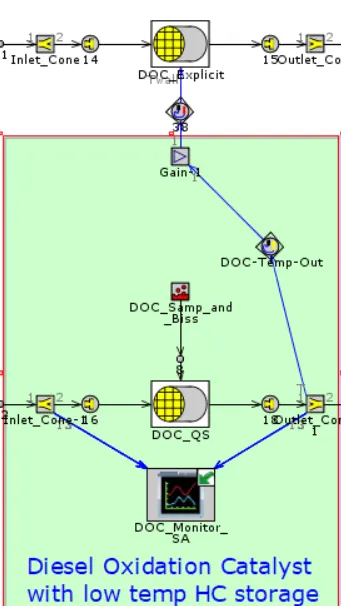
The data from the Inlet_Cone-1 and the outlet_Cone-1 are monitored on the DOC_Monitor. The output signal from the outlet_Cone-1 is sent to DOC-Temp-Out. From the DOC-Temp-Out the signal is sent to the "Gain" template. This template produces an output signal which is the input signal multiplied by a scalar value. A "ActuatorConnection" template is a link between the controls library and the multi-physics library(i.e. flow, mechanical, thermal, etc.). Based on this signal the DOC_Explicit is actuated.
Diesel Particulate Filter
The particulateFilter template is for a wall-flow filter i.e. Diesel particulate filter, Gasoline particulate filter etc. Here we define the basic parameters like diameter, length, channel size, etc. Also the total cell density and the initial state object is defined. The FluidInitialState template specifies the initial pressure, temperature and all other fluid properties in the flow components also can be reffered by any flow component with the volume.
Here for the DOC_QS, a SurfaceReactions template is connected in which it specifies the catalytic surface reaction kinetics that require the modeling of storage.
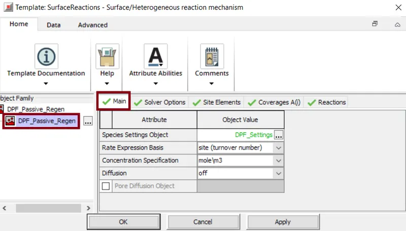
In speciesSettings object, reference object "DPF_Settings" is used for mapping the species specified in GaseousReactions, SurfaceReactions to the basic fluid objects.
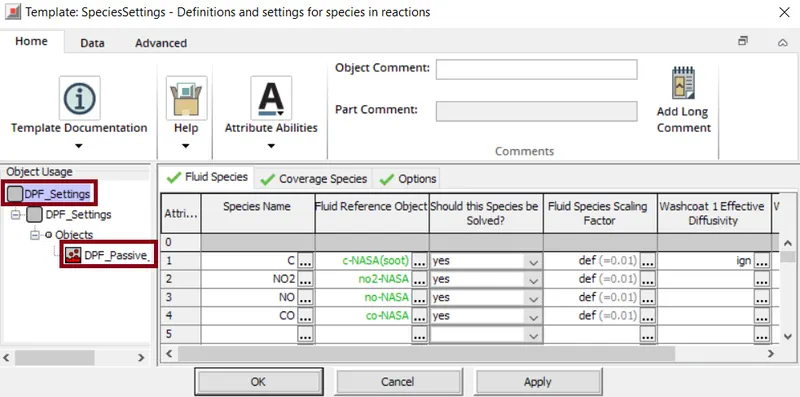
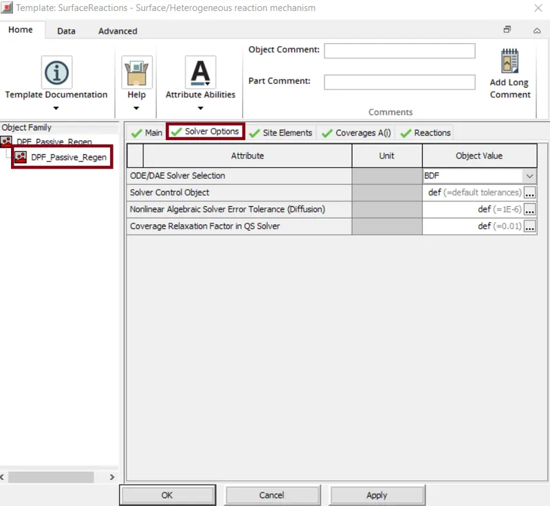
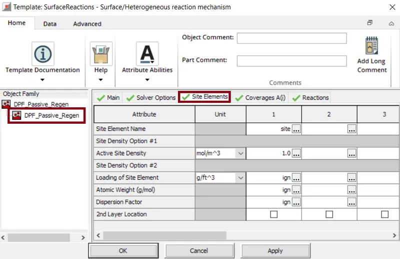
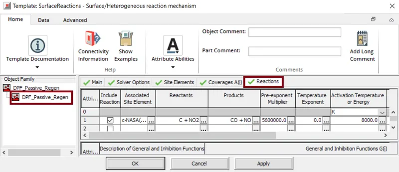
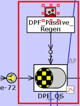
The output from the outlet_Cone-1 is sent through the orifice connection to DPF_QS. The data from the DPF_QS is monitored on the DPF_Monitor. The output signal from the DPF_QS is sent to DPF_dp. This template provides control sensor link betweenphysical parts such as flow , mechanical, electrical, thermal or chemical parts and control components parts. From the DPF_dp the signal is sent to the "Gain" template. This template produces an output signal which is the input signal multiplied by a scalar value. A "ActuatorConnection" template is a link between the controls library and the multi-physics library(i.e. flow, mechanical, thermal, etc.). Based on this signal the DPF_Explicit works.
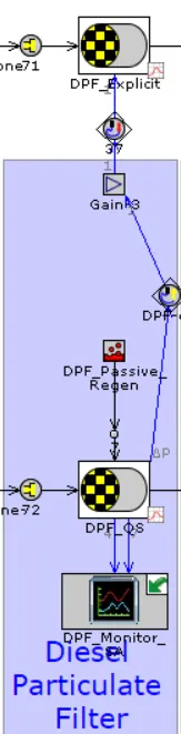
As the particulate matter starts accumulating very frequently. There should be some automation in the regeneration statergy. Here we need active regeneration i.e. we inject some amount of fuel in exhaust then it comes with the exhaust and get deposited. Because of high temperatures it starts burning and hence the particulte matter is minimized. We meassure the pressure drop and signal goes to ECU and based on calculate we can decide if the regeneration is required or not.
Selective Catalytic Reduction
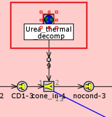
From the DPF_QS, the flow flows through orifice connection. This is considered as first stage for considering how much urea is required. Next the flow flows from the OrificeConnection to pipeRound template. In this step "UreaControlStrategy" identifies and controlls the urea injection into the pipe, also again the signals are sent back to the controller to check if the right amount of urea is injected or not. Later it flows through "FlowSplitGeneral".Here the "User_thermal_decomp". 'User_thermal_decomp' is a global reaction template that specifies kinetics with a set of global reactions.
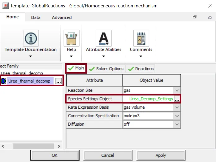
In speciesSettings object, reference object "Urea_Decomp_Settings" is used for mapping the species specified in GaseousReactions, SurfaceReactions to the basic fluid objects. Along with this the signal from "FlowSplitGeneral" is monitored in 'Assembly25'.
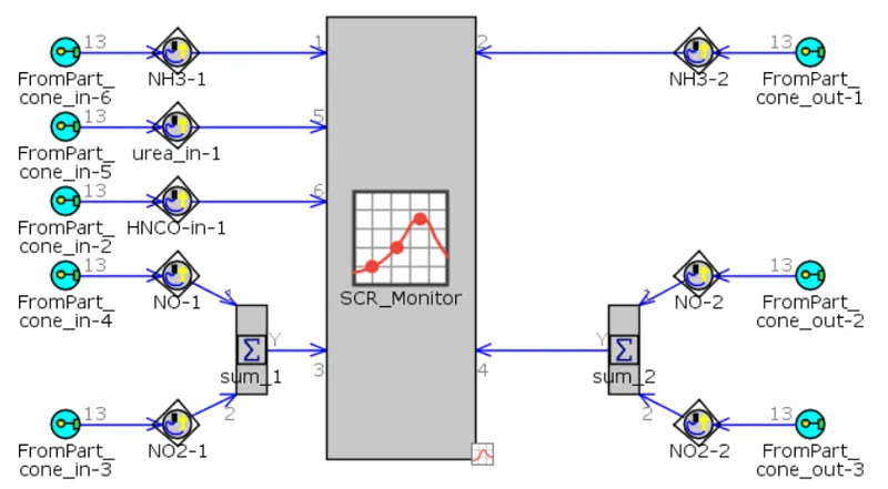
The CatalystBrick template helps to represent the flow through the catalyst.Here we provide various parameters that are related to catalyst substrate. The initial state object is provided with reference object describing the initial conditions of the gas inside the catalyst.
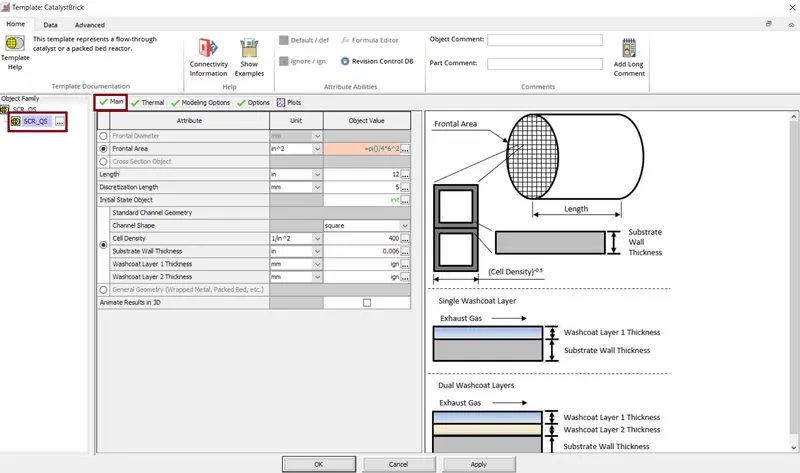
Here for the SCR_QS, a SurfaceReactions template is connected in which it specifies the catalytic surface reaction kinetics that require the modeling of storage.
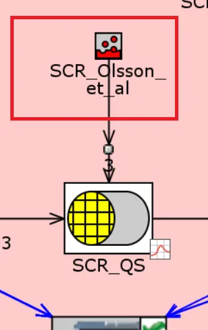
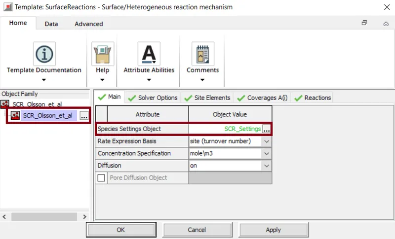
In speciesSettings object, reference object "SCR_Settings" is used for mapping the species specified in GaseousReactions, SurfaceReactions to the basic fluid objects.
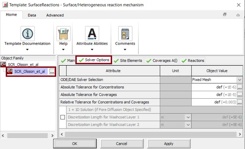
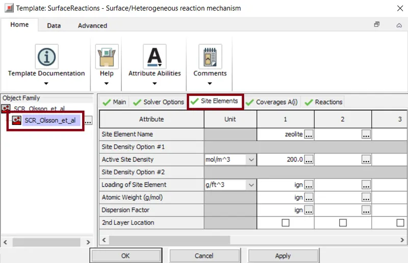
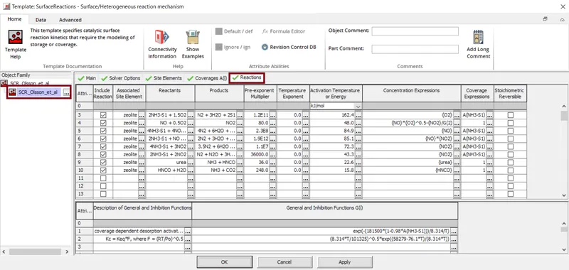
Now the flow flows through the 'cone_out-1'i.e. flowSplitGeneral template. The data flowing through this template is also monitored in Assembly25. From this one signal is sent to "UreaControlStrategy". This helps to identify how much amount of urea to be injected at inlet pipe before SCR. And other signal is cent to 'SCR-Temp-Out'. From the SCR-Temp-Out, the signal is sent to the "Gain-2". This produces an output signal which is the input signal multiplied by a scalar value. A "ActuatorConnection" template is a link between the controls library and the multi-physics library(i.e. flow, mechanical, thermal, etc.). Based on this signal the SCR_Explicit is actuated.
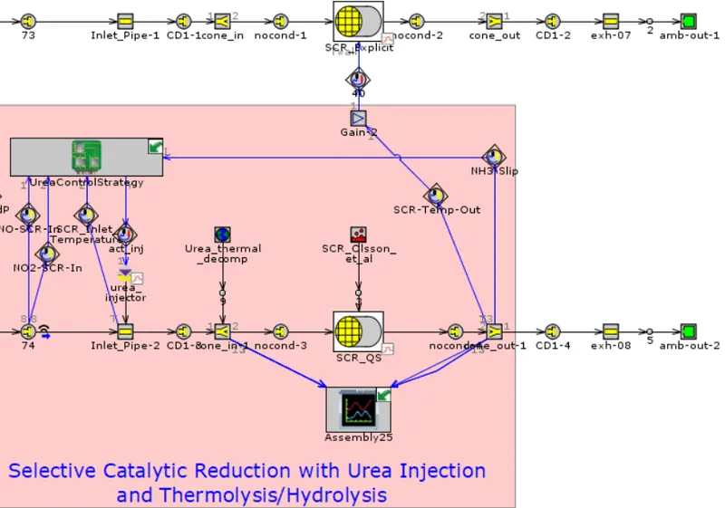
Now the flow passes through FlowSplitGeneral and passes through amb-out-1. The accuracy of the simulation mainly depends on how accurately we capture the physics.
2. Detailed_SI_Engine_Aftertreatment:-
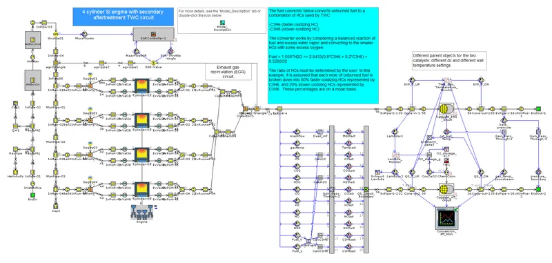
Here this case demonstrates the modeling an SI Engine combined with TWC in a secondary aftertreatment circuit.The original base model SI 4Cyl EGR Controller was combined with the aftertreatment model TWC_Ramanathan_&_Sharma.
Also a secondary circuit is used to solve the reactions using a quasi-steady flow solver, where we can use large master time-step and hence it doesnt restrict the computational time.
The engine used in this case is a 4-stroke engine by specifying the engine speed as well as kind of load acting on it.
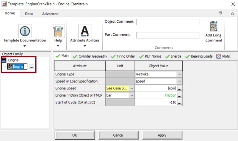
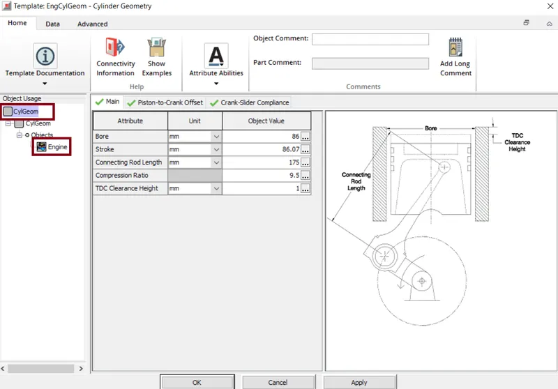
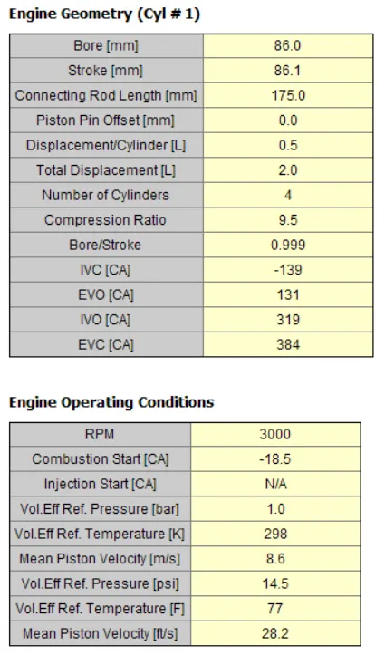
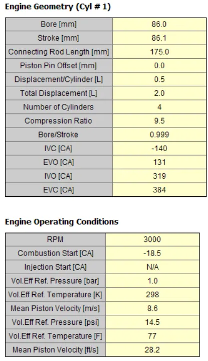
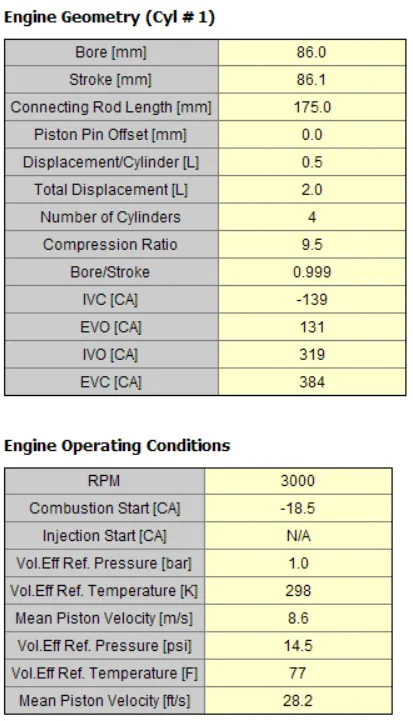
'EngCylGeom' template is used to specify the physical geometry of the engine cylinders and the cranktrain. Here Bore=86mm, Stroke=86.07mm, Connecting Rod length=175mm, Compression ratio=9.5.
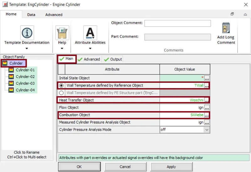
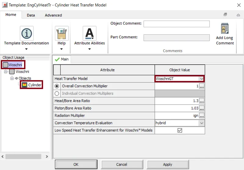
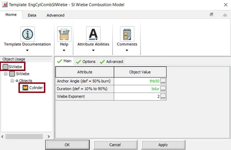
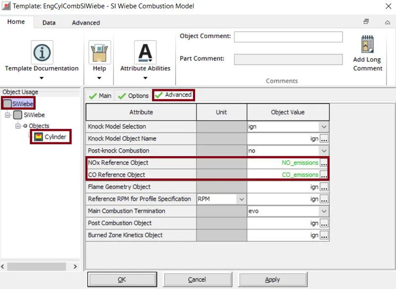
In the 'EngCylinder' we specify the wall temperatures, heat transfer object, combustion object, etc. For the temperature we use reference objects to define the cylinder-wall temperatures i.e. in this case 'TWall' is selected as reference object and for the Heat transfer object for this case we have selected 'WoschniGT'. For the Combustion object bascially specifies the in-cylinder combustion model i.e.'SiWiebe' is selected as this imposes the combustion burn rate for the spark ignition engines using a Wiebe function. Also we specify the required emission species for the outlet to be captured. The NOx model considered is 'Extended Zeldovich'.
The exhaust of the engine is connected to the various aftertreatment devices like EGR (Exhaust Gas Recirculation), Three-way catalytic convertes etc for gasoline or SI engines. In this case all the output gases from all the 4cylinders are collected into the 'collectors'.
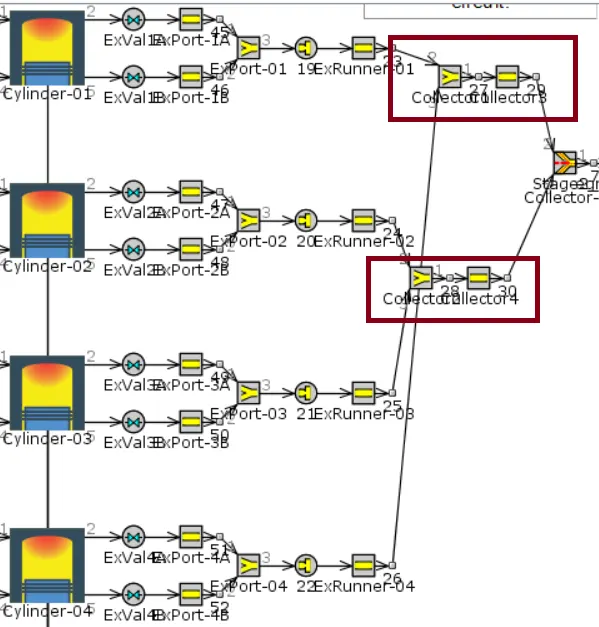
Once the exhausted gases are collected a 'FlowSplit-Y' is used to combine all the flow from collectors into a single flow i.e. 'Stage_Collector-1'. As we are using two after treatment devices we use a 'FlowSplitTAngle' such that from one line it passes to EGR and the other line passes to three-way catalytic converter.
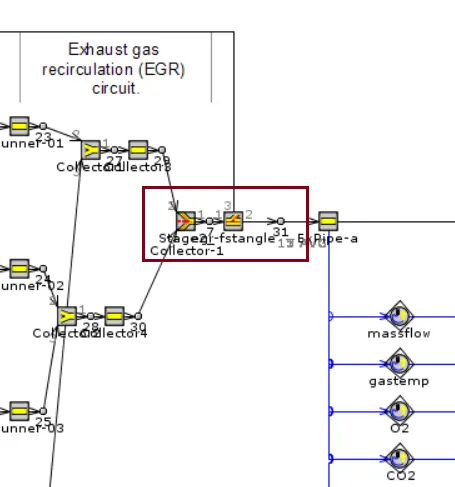
Exhaust Gas Recirculation(EGR) is a nitrogen oxide emissions reduction technique used in gasoline and diesel engines.EGR works by the recirculating a portion of an engines exhaust gas back to the engine cylinders. This helps to dilute the O2 in the incomming air stream and provides gases inert to combustion to act as absorbents of combustionheat to reduce the peak in-cylinder temperatures.
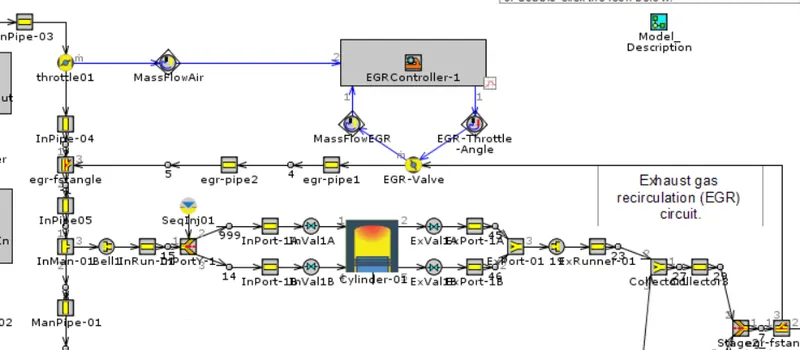
At the 'throttle01 valve', the mass flow rate is sensed and sent to the EGR Controller. This controller also controlls the the EGR valve opening and closing so that the required gases flow through them. Also the mass flow rate at the 'EGR-valve' is monitored by mass flow EGR sensor and the signal is sent to the 'EGR Controller-1'. In this way some amount of exhaust gas is recirculated back to the engine and rest of the emitted gases are sent to the 3-way catalytic converter.
A catalytic converter is an exhaust emission control device that reduces toxic gases and pollutants in exhaust gas from an ic engine into less toxic pollutants by catalyzing a redox reaction.
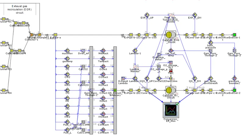
Here we have two different circuits i.e the primary circuit is connected directly to the exhaust line and the secondary circuit is used to solve the reactions using the Quasi-steady state solver, which uses a large time step so that it has sufficient computation time.
From the exhaust gas all the parameters like mass flow rate, temperature, different mole fractions of species
i.e. CO2, O2, H2O, CO, H2, NO, NO2 are captured and the data is collected using sensors. All this data is passed through the output signal(which is the input signal multiplied by a scalar value).
These output signals are linked to the actuators i.e. this is a link between the controls library and the multi-physics library.
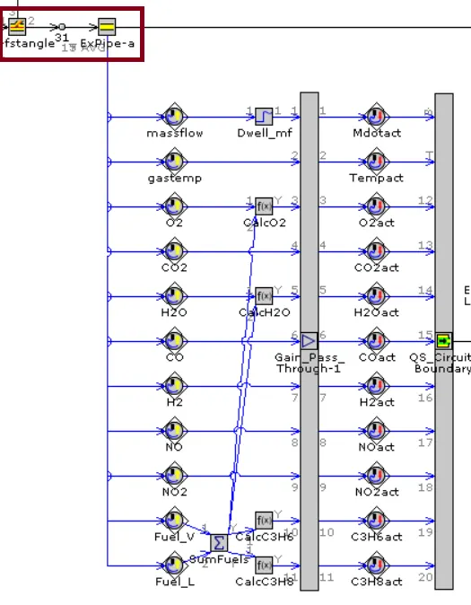
The above signals are recorded and forwarded to the quasi state circuit which helps to calculate the physics using this solver. Here the 3-way catalytic converter model is selected fro the existing example model i.e. TWC_Ramanathan_and_Shama.
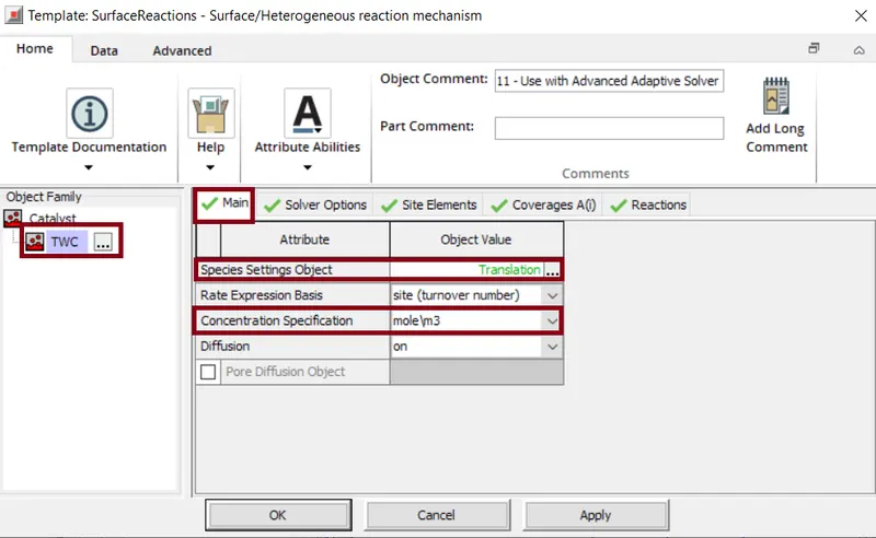
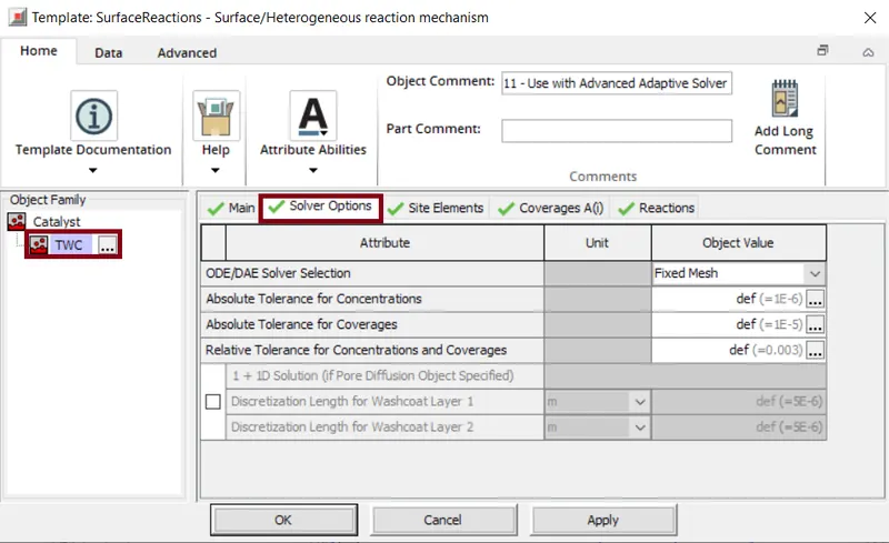
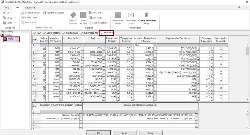
The template 'SurfaceReactions' specifies the catalytic surface reactions that require the modeling of storege. Here the parameters of the species are set using a reference object "Translation" and concentration of species is measured by mole/m^3, also diffusion is set to ON. In solver options we can select the ODE/DAE solver methods. For each species specified we include reactions which help to solve the physical behaviour. Various reactions are carried out to find the optismistic outcomes.
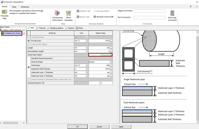
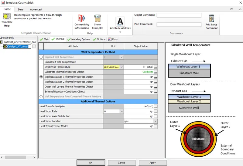
For the catalyst(Catalyst_AT_circuit) we specify the frontal area , length, discretization length, Initial state object='ExhaustInit'. The thermal properties like initial wall temperature etc are also mentioned. In the modeling options we select 2D/3D flow discretization Method= 'component(QS)'.

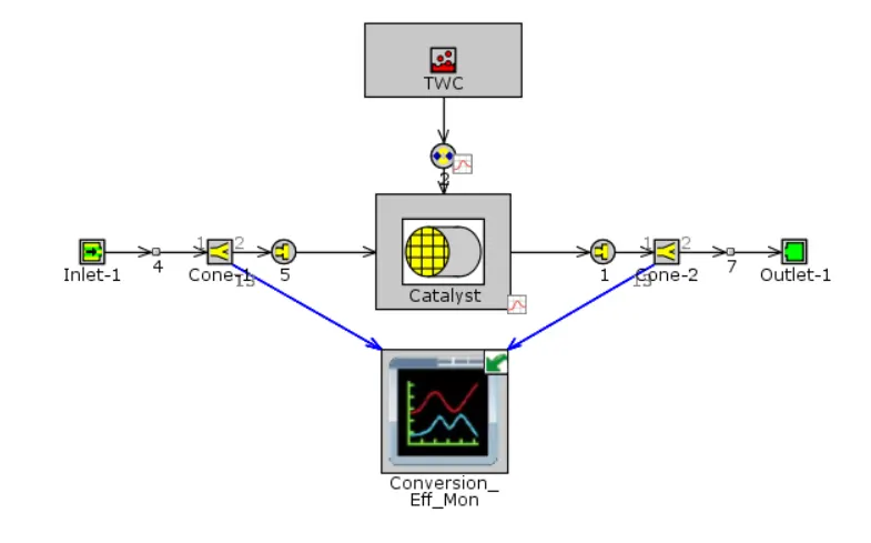
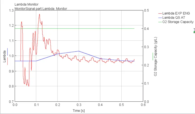
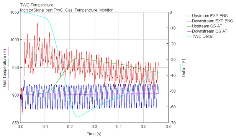
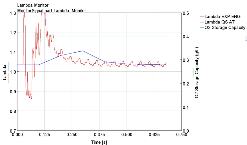
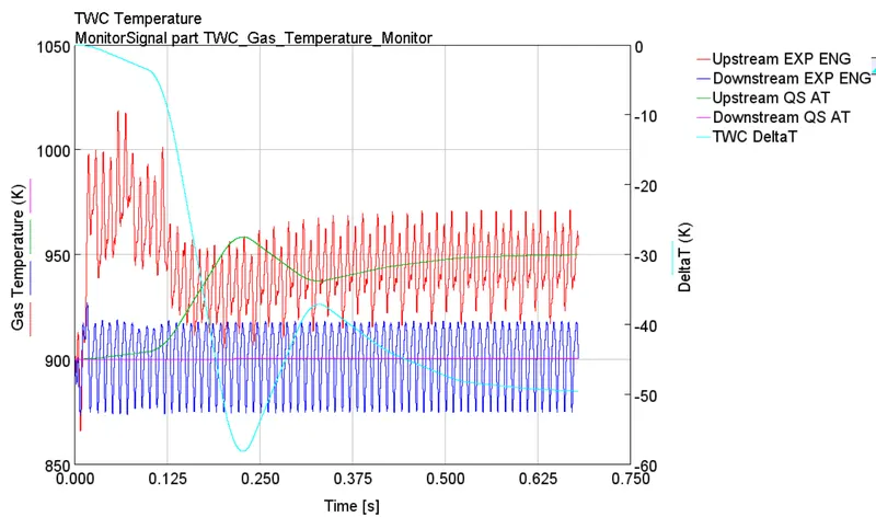
The gas temperature of the flow before entering the catalyst and temperature of the flow leaving the catalyst for both the circuits are monitored in the TWC_Gas_Temperature Monitor.Once the exhaust gases are emitted the lambda sensor senses and is monitored in the Lambda_Monitor.The amount O2 present after the reactions takes place is monitored in the lambda monitor.
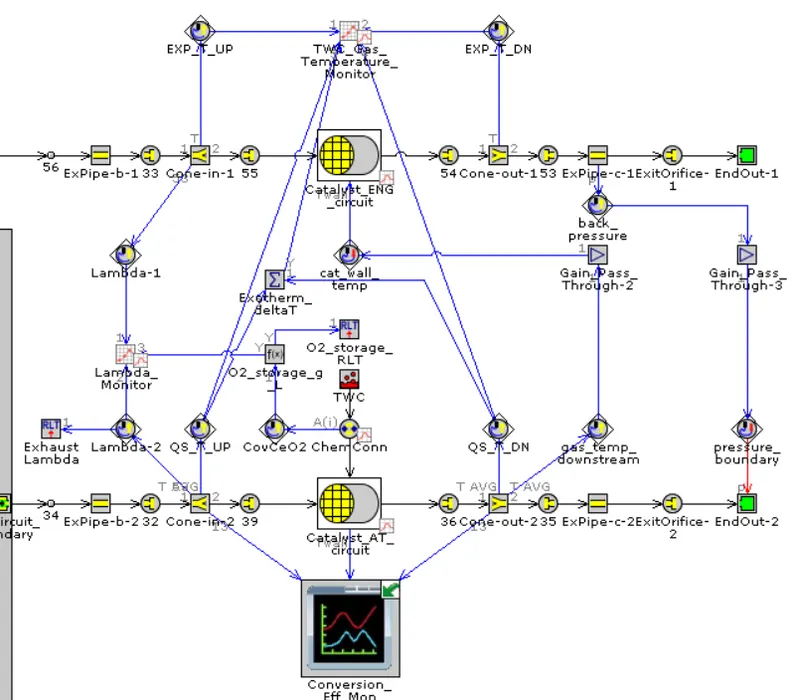
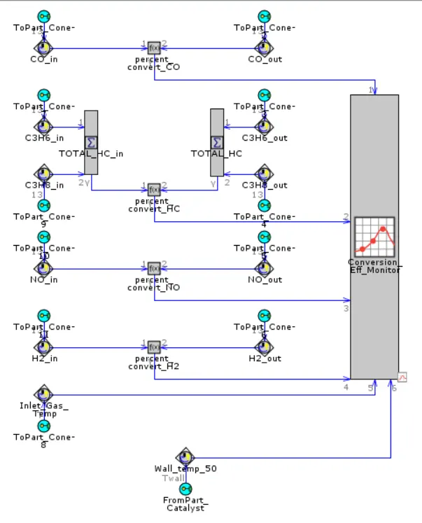
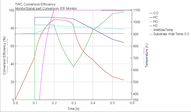
The wall temperature in the catalyst is monitored in the 'Conversion _Efficiency_Monitor'. Another signal from the gas before entering to the catalyst and gas leaving the catalyst is also monitored. The temperature of gas that is out from catalyst circuit sends the output signal to the 'Engine_Catalyst_Circuit'. This actuates and then based on the signal the Engine catalyst starts maintaining its temperature.Once the gas starts comming out then it undergoes back pressure. Back pressure is mainly produced by the engine to overcome the hydraulic resistance of the exhaust system in order to discharge the gases into the atmosphere. Because of this the pressure in the exhaust is measured, this measured quantity is considered as the input for the Quasi-circuit and send signals to the EndEnvironment variables. Then the gases flows out through the exhaust system.
3. Comparing results of both the cases:
Results of Detailed_CI_Engine_Aftertreatment
Case Setup:
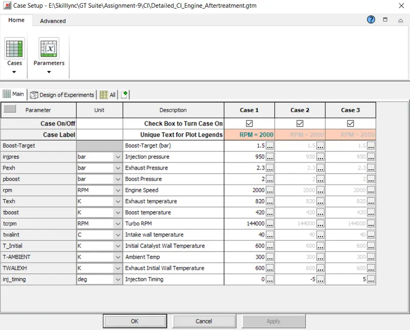
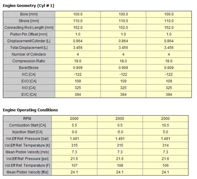
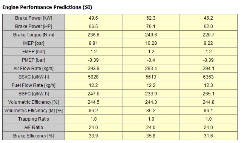
Case-1 Injection Start=0deg (CA)
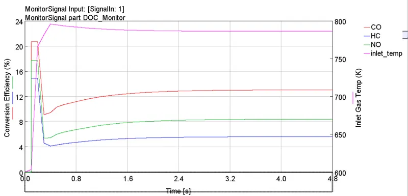
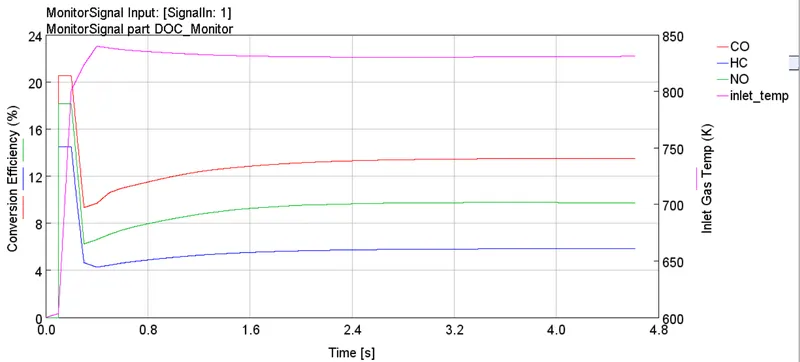
The first plot displays the conversion efficiency for CO,HC and NO. As the temperature is increasing and when it reaches the temperature it will start converting the emissions. Here the convergence efficiency of CO and HC is low, so we require high convergence efficiencies.
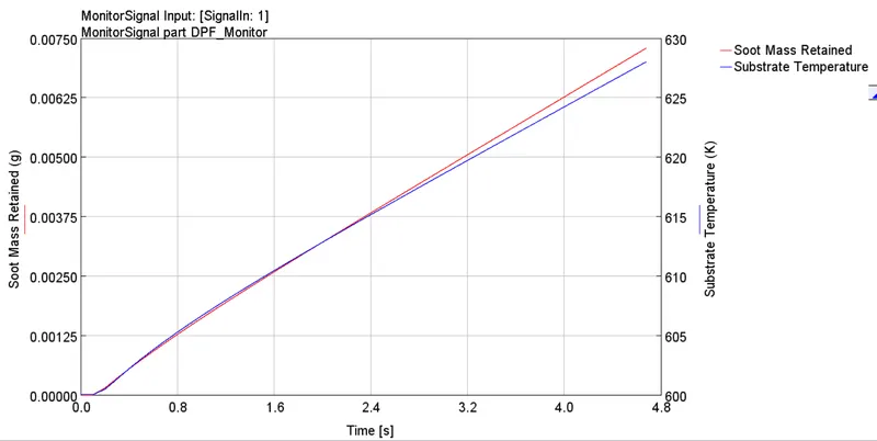
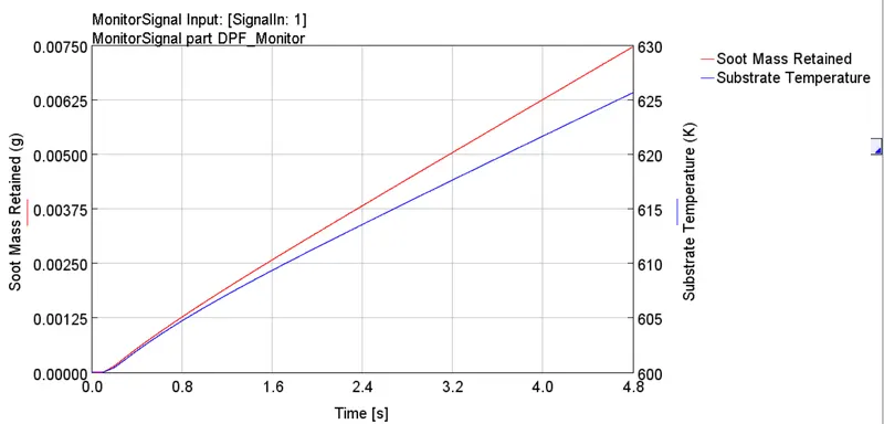
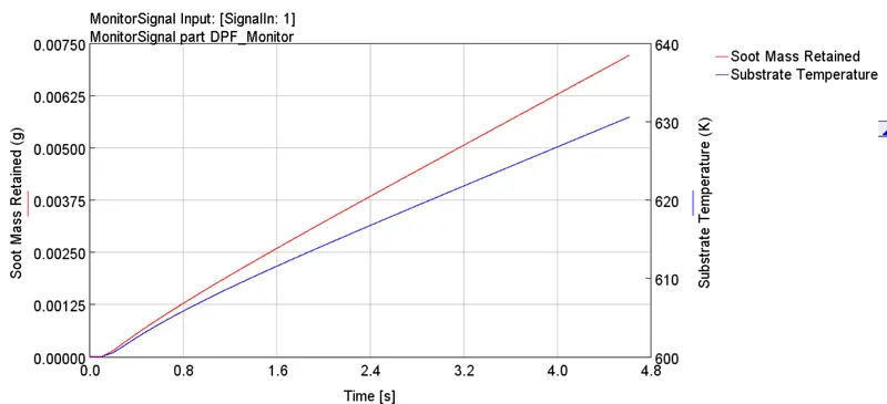
The plot indicates the capturing of soot and the substrate temperature.Here we can observe that the Soot Mass Retained is increasing as the time increases and at apoint it is getting deposited. Generally when the soot is deposited, the engine out particulate matter consists of oil bound soot also. Small part of soluable fraction is converted in DOC also. Hence this reduces the soot accumilation in DPF. In some cases of passive regeneration due to high temperatures, the soot deposited get burnt simultaneously.
In this case BSFC= 247 g/KW-h.
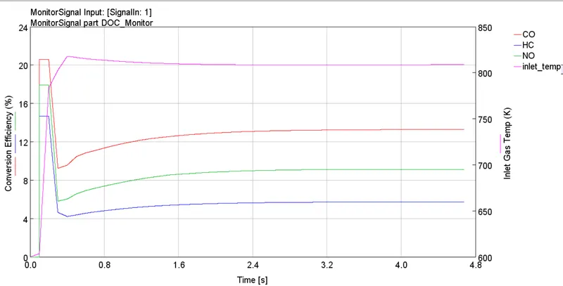
Case-2 Injection Start=-5deg (CA)
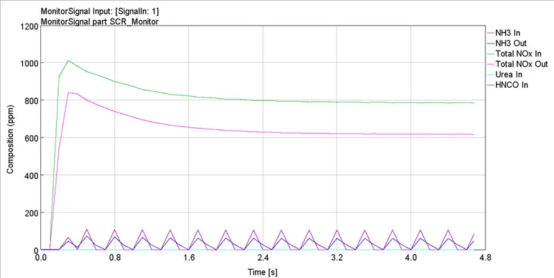
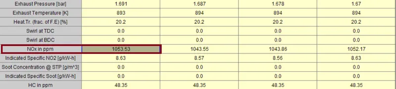
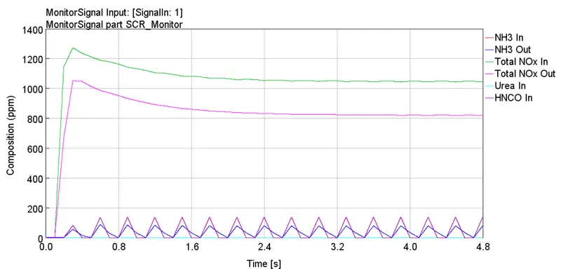
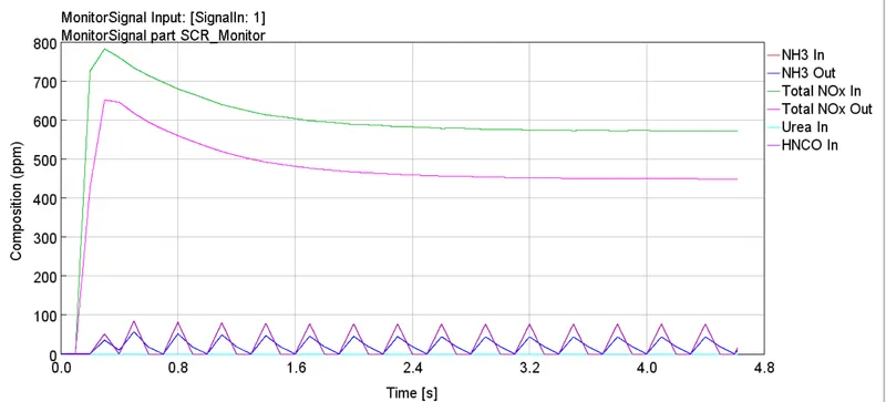
In this case we have addvanced the timing we can see the changes in the emission properties that are mentioned in the above table. From SCR_Monitor plot we can see that the NOx has increased on advancing the engine start i.e. for 0deg crank angle the NOx In is approx 800 and after advancing the 'NOx In' is raised to 1053ppm. In this case BSFC=233.9 g/KW-h. The BSFC value is improved compared to the initial case. In SCR, the maximum value is 1044 ppm and can go minimum upto 820 ppm.
Case-3 Injection Start=5deg (CA)
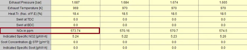
As we are retarding the timing here, the soot value is increasing when compared to the previous cases. Here there is a huge decrease in the engine NOx value. The BSFC=265 g/KW-h. The NOx value is around 573 ppm. So we can see the decrease in the NOx and BSFC value.
Results of Detailed_SI_Engine_Aftertreatment
Case Setup:
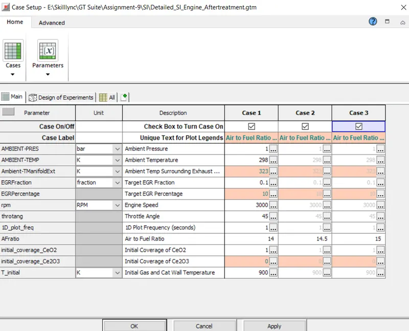
In the above case setup we are monitoring various parameters by varying the Air/Fuel ratio.
Case-1 Air-Fuel Ratio=14
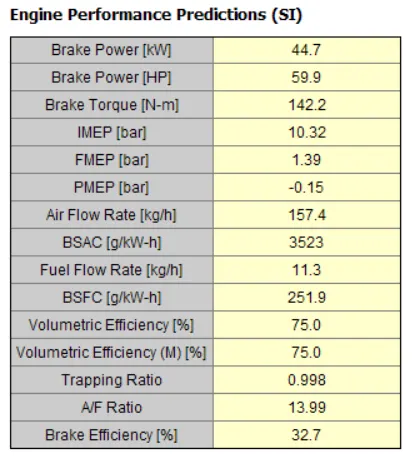
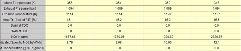
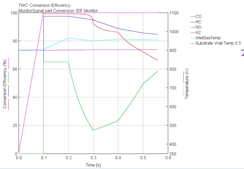
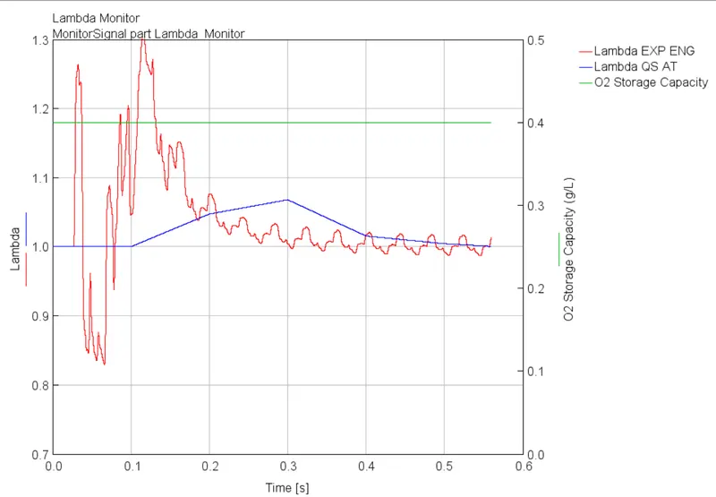
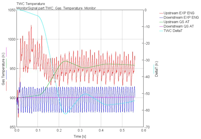
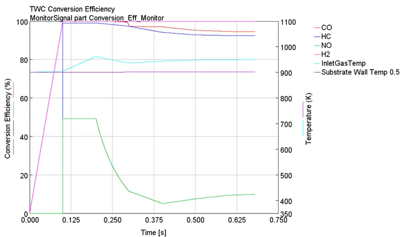
From the below tables it is observed that for the air to fuel ratio of 14 the BSFC value obtained is 251.9 g/kW-h and NOx obtained is 1667.6ppm. The first plot indicates the effeciency of the 3way catalytic converter. From the plot the conversion efficiency is increased to high and at a point of time it decreased as the time increases and the temperature decreases. The c.efficiency of NO is close to 100% for this case. The lambda monitor helps to see how much amount of unburt oxygen present in the exhaust. The output of the sensor is used to adjust the air-fuel mixture. Also this sensor determines whether the air-fuel mixture is rich or poor. In the temperature monitor plot it displays the exhaust gas temperatures of the actual circuit and the quasi state circuit.
Case-2 Air-Fuel Ratio=14.5
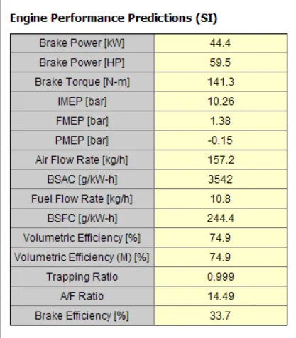
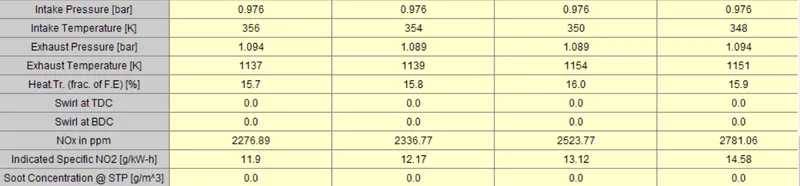
Here we increased the Airfuel ratio to 14.5. The obtained BSFC value in this case is 244.4 g/kW-h and NOx obtained is 2276.8ppm. Which means we can see there is a decrease in value of BSFC and increase with increasing the Air-Fuel ratio. In Converssion efficiency monitor, the CO value is high when compared to the case1. Also the c.efficiency of NOis a bit lower compared to case1. The lambda monitor helps to see how much amount of unburt oxygen present in the exhaust. The output of the sensor is used to adjust the air-fuel mixture. We can see the increase in the lambda value for this case.In the temperature monitor plot it displays the exhaust gas temperatures.
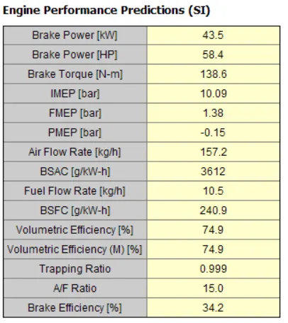
Case-3 Air-Fuel Ratio=15
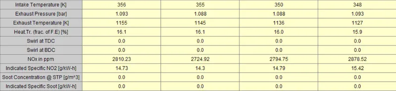
Here we increased the Airfuel ratio to 15. The obtained BSFC value in this case is 240.9 g/kW-h and NOx obtained is 2810.23ppm. Which means we can see there is a huge decrease in value of BSFC and increase of NOX with increasing the Air-Fuel ratio. In Converssion efficiency monitor, the CO value is almost close as in casse2 and high when compared to the case1. On comparing the above two case the percentage of NO is low for this case.The lambda monitor helps to see how much amount of unburt oxygen present in the exhaust. The output of the sensor is used to adjust the air-fuel mixture. We can see the increase in the lambda value for this case.In the temperature monitor plot it displays the exhaust gas temperatures.
Conclusion:
- Both the Detailed SI engine+aftertreatment and Detailed CI engine aftertreatment examples are explored.
- The results of all cases in both the examples are compared.