Aftertreatment Modeling Techniques - IC-Engine Calibration Using GT-Power and GT-Suite.
IC-Engine Calibration Using GT-Power and GT-Suite
Assingment:8 (Aftertreatment Modeling Techniques)
Objectives:
- To study the comparision between following parameters for Gasoline engine and Diesel engine;
- The pollutants.
- Aftertreatment devices with catalyst materials.
- Explore example files.
- Strategies used for reducing tail pipe emissions.
- List down one set of chemical reactions for TWC and SCR from example files.
- Exploring example of Aftertreatment-DOC-Sampara & Bisset with a detailed report.
Description:
An aftertreatment system is a method or device for reducing harmful exhaust emissions from internal-combustion engines. It is a device that cleans exhaust gases to ensure the engines meet emission regulations.
Comparision between Gasoline engine and Diesel engine:-
The pollutants-
A pollutant is a substance that is introduced from the exhaust of the engine which has undesired effects on the environment.
Gasoline engines operate at stiochmetric air-fuel ratio, so the emissions of CarbonMonoxide(CO)and HydroCarbons(HC) are always higher compared to diesel engines. Where as in diesel engines , they operate at much leanier air-fuel ratio, so the emissions of CO and HC are very less.
As the Gasoline engines operate at stiochmetric air-fuel ratios the quantity of air present per gram of fuel burnt is low. In gasoline engine the peak pressure is low as the compression ratios are lower and hence the NOx production is lower for Gasoline Engines. Diesel Engine generally operate at lean mixtures as the quantity of air present per gram of fuel burnt is higher. In diesel engine,the peak pressure and temperature is high as the compression ratios are much higher and hence NOx(gaseous nitrogen oxides) is produced in diesel engines. NOx is produced in combustion chamber mostly from nitrogen in the air. Nox is generally in-cylinder temperature dependent. NOx can be reduced by controlling incylinder pressure, exhaust gas recirculation,control rate of fuel burning etc.
The fine particles i.e. the particulate matter or soot is produced from Diesel engines and very rare from Gasoline engines. These especially harmful particulate contaminants are at the peak when such engines run without sufficient oxygen to fully combust the fuel.Where as when diesel engine runs at idle conditionenough oxygen is usually present to burn the fuel completely. In case of Gasoline Engines, the mixture is homogeneous and the flame produced from the spark propagates completely in the volume of the combustion chamber and hence no soot is produced in case of Gasoline Engines. Soot is a solid Carbon and can be minimised by controlling Air-Fuel mixing (swirl, bowl desin), sufficient Air availability(turbocharging) etc.
The diesel fuel(2.68Kg CO2/litre) contains slightly more amount of carbon than compared to petrol (2.31Kg CO2/litre). Overall CO2 emissions of diesel engine are lower(On average 200g CO2/km for petrol and 120g CO2/km for diesel).
Aftertreatment devices with catalyst materials-
Two-Way Catalytic Converters:
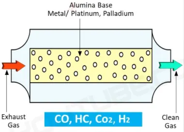
A two way catalytic converter is designed for two things i.e.
It allows to oxidize the CO (carbon monoxide) to turn it into CO2 (carbon dioxide).
It helps to oxidize the hydrocarbons or the unburnt fuel and convert them into carbon dioxide and water(H2O).
The exhaust gases are directed to flow through the substrate, containing metals like platinum , palladium which allow the chemical reaction to occur. The exhaust gases increase in temperatures as the conversion process takes place. Because of the intense heat created by the process the exhaust gases leaving the converter should created by hotter compared to the gasses entering the converter. Catalyst used are Platinum, Palladium.
Three-Way Catalytic Converters:
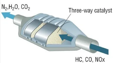
It allows reduction of NOx(nitrogen oxides) to N2(nitrogen) and O2(oxygen).
Allows oxidation of CO(carbon monoxide) to CO2(carbon dioxide).
Allows oxidation of HC (unburt hydrocarbons) to CO2(carbon dioxide) and H20(water).
The engine exhaust gases contains hazardous substances that cause damage to environment. These include the oxides of nitrogen, hydrocarbons, and carbonmonoxide.This three way converter converts them into carbon dioxide, water, and nitrogen.The 3-way catalytic converter consists of two different catalysts i.e. reduction catalyst & oxidation catalyst. The oxidation catalyst is made of palladium and platinum where as reduction catalyst is made of rhodium and platnium. oxidation catalyst is made of palladium and platinum and reduction catalyst is made of rhodium and platnium.
Diesel Oxidation Catalyst:
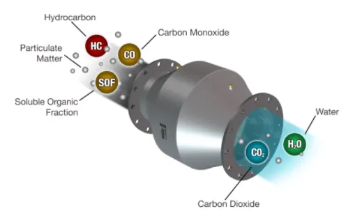
DOC are catalytic converters designed specially for diesel engines equipment to reduce Carbon Mooxide(CO), Hydrocarbons (HC) and Particulate Matter(PM) emissions. The device uses O2 in the exhaust gas stream to convert the carbon monoxide to carbon dioxide. These converters perform at 90% efficiency. A minimum exhaust temperature of 200deg is necessary for the catalyst to light off.
Catalyst Used:- Palladiumis the catalyst material.
Diesel Particulate Filter:
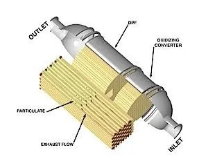
DPF operates by trapping soot particles from the engine exhaust, preventing them from reaching the atmosphere.The particulate filter is designed to trap and retain the solid particles untill the particles can be oxidized in the DPF itself through the process called regeneration. Te soot containing the exhaust to flow through the porousfilter walls.While the gas flows through the walls, soot particles are trapped within the filter pores. The honey comb design of the filter provides a large filteration area while minimizing the pressure losses. Ceramic materials(like silicon carbide) are widely used for particulate filters, they provide good thermal durability.
Selective Catalytic Reduction(SCR):
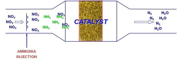
SCR is a means of converting nitrogen oxides (NOx)by means of the catalyst into Nitrogen(N2) and Water(H2O). We inject Ammoniato a stream of exhaust gas and is observed onto a catalyst. When the Urea comes in contact with the hot exhaust , it converts into Ammonia gases then the ammonia gas reacts with the exhaust gases in presence of catalyst to form N2 and H2O. The efficiency of the catalytic reduction depends on various factors like, dosage of the reducing agent, the volume of catalyst elements and the exhaust gas temperatures.
Example Files-
3-Way Catalytic Converter:
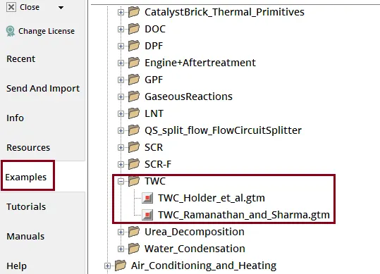
TWC_Holder_et_al.gtm:
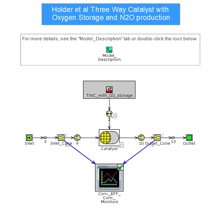
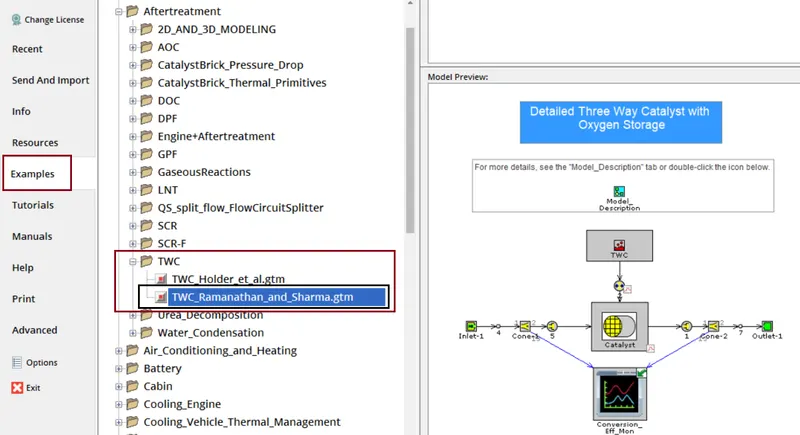
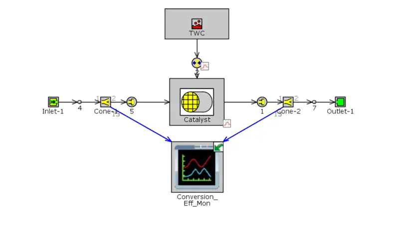
TWC_Ramanathan_and_Sharma.gtm:
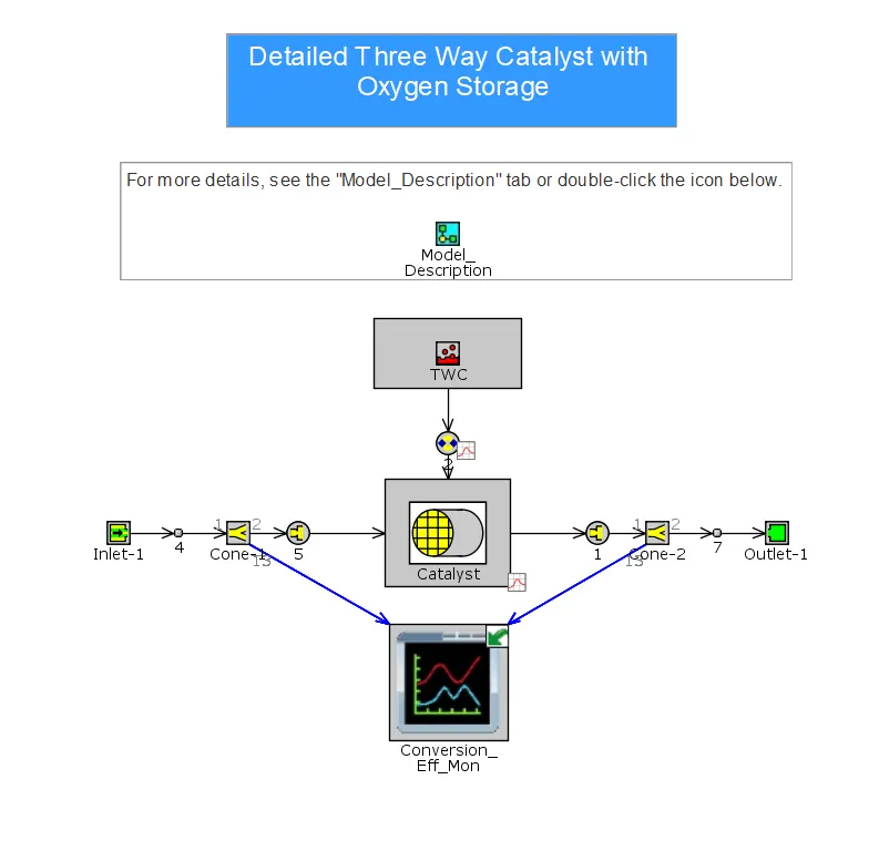
Diesel Oxidation Catalyst:
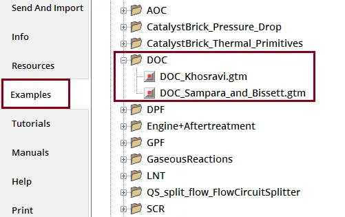
DOC_khosravi.gtm:
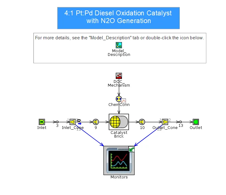
DOC_Sampara_and_Bissett.gtm:
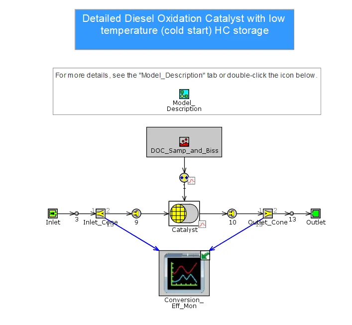
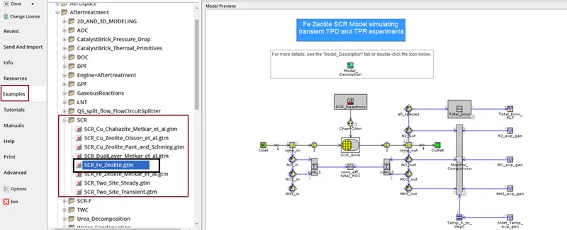
Selective Catalytic Reduction:
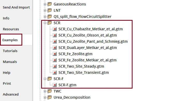
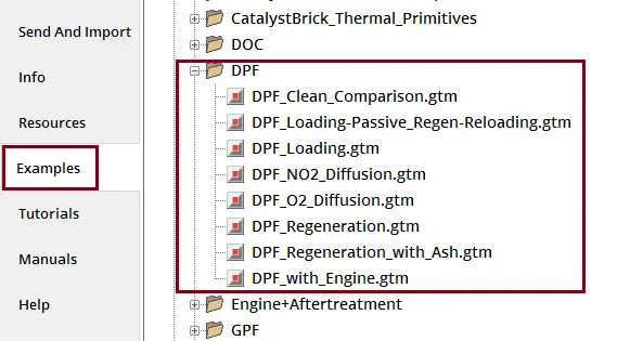
Diesel Particular Filter:
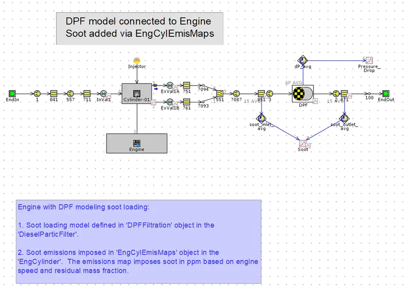
DPF_With_Engine.gtm:
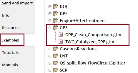
Gasoline Particulate Filter:
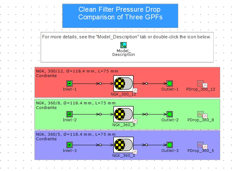
GPF_Clean_Comparision.gtm:
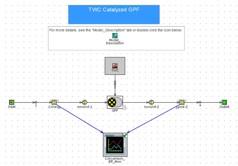
TWC_Catalized_GPF.gtm:
Strategies used for reducing tail pipe emissions:-
The emission control techniques are grouped into following categories;
- Engine design and fuel system parameters
- Exhaust Aftertreatment technology
Engine design and fuel system parameters(SI-Engine):
The following engine parameters have large influence on emisssions i.e.
- Engine compression ratio
- combustion chamber design
- spark timing
- Air-Fuel ratio
- Fuel system design
- Variable valve actuation
- Engine Temperature control
Engine compression ratio- Engine compression ratio effects the surface to volume ratio of the combustion chamber, engine combustion temperature, thermodynamic efficiency, fuel octane number for knock free engine operation. The combustion chamber with low CR ha a lower surface/volume ratio resulting in a reduction in volume of quench layer on combustion chamber surface. Higher exhaust temperatures resulting with low CR would pramote oxidation of HC & CO in exhaust system. At low CR the peak combustion temperatures are lower hence low NOx formation. The disadvantage of low CR engine is that it has a poor fuel efficiency that also results in high CO2 emissions.
Combustion chamber design- On improving the combustion concepts we can improve the efficiency through faster combustion and reduced heat loses during the exhaust.
Fuel System- Shifting from port injection to Gasoline Direct Injection(GDI) was driven by the use of engine downsizing to meet fuel consumption and CO2 requirements. Direct Injection and air assisted injection system can improve combustion and can reduce the concentration of the exhaust gas pollutes.
Variable valve actuation- It is one of the important measure to reduce cold start HDs. Variable valve lifts enables throttless operation and provide improvide efficiency. Cylinder deactivation reduces part load pumping losses and improves efficiency. VVT allows for continuously variable camshaft phasing over the entire power range of the engine.
Exhaust Aftertreatment technology(SI-Engine)-
- Oxidation Catalyst(OC)- HC and CO emission reduction.
- Three-Way catalyst(TWC)- NOx, HC & CO emission reduction.
- NOx adsorber Catalysts- NOx reduction.
- Gasoline Particulate Filters(GPF)- Particulate matter emission reduction.
Engine design and fuel system parameters(CI-Engine):
The following engine parameters have large influence on emisssions i.e.
- Engine compression ratio
- combustion chamber type
- combustion chamber design
- Fuel Injection system: (Injection pressure & timing, nozzle holes)
Engine compression ratio- Generally the compression ratios are higher for diesel engine compared to gasoline engines.The use of higher compression ratios results in a shorter ignition delay period. A shorter delay results in less overmixingog fuel and air and hence lower HC emissions.The higher combustion temperatures acheived at heigher compression ratios tend to increase oxidation of the unburned HC. At low CR, a longer delay increases the fraction of fuel burned during the premixed phase resulting in higher peak pressure and temperatures which causes increases in NOx formation.A high compression ratio leading to high combustion temperatures would increase soot formation. In order to obtain low particulate and NOx emissions simultaneously, an optimum compression ratio is to be used.
Combustion Chamber Design- Air in the combustion chamber is contained in different volumes like piston bowl, top land crevice, piston-cylinder head clearance and head gasket clearance.The piston bowl in diesel engines contains slightly more than 50% of total clerance volume at TDC. The air contained in the top land crevice, head gasket clerance and valve recess is nearly 15% iand is poorly utilized during combustion.A lower clerance between piston and cylinder head increases air utilization and reduces the possibility of fuel entering.Using 3-4 valves per cylinder increases flow area and hence the volumetric efficiency of the engine also increases.
Fuel Injection system- If there is retarded injection timing, the NOx emissions decreases sharply. If the injection timing is retarded extremely, HC emissions in naturally aspirated engines also may increasy sharply. An increase in injection pressure results in higher NOx and HC but lower smoke and PM emissions.
Exhaust Aftertreatment technology(CI-Engine)-
- Diesel Oxidation Catalysts(DOC)- Reduction of HC/CO emissions, small to mderate PM conversion. The oxidation of NO to NO2 enhances the performance of SCR/DPF systems.
- Diesel Particulate Filters(DPF)- Maximum 90% of PM emission reduction.
- Selective Catalytic Reduction(SCR)- SCR helps to reduce the level of NOx using Ammonia as the reductant within a catalyst system.
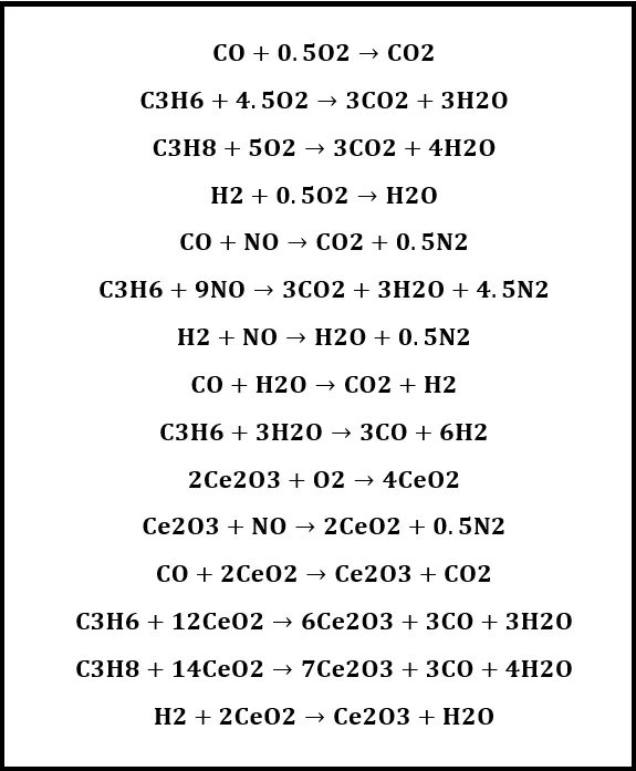
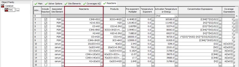
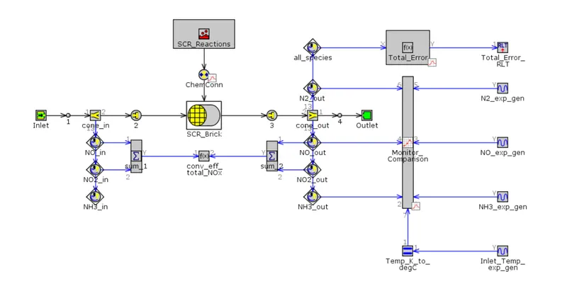
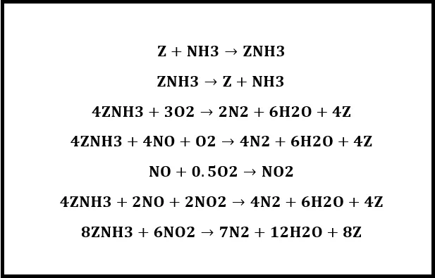
List down one set of chemical reactions for TWC and SCR from example files:-
TWC:
Reactions:
SCR:
Reactions:
Explore Example-aftertreatment-DOC-sampara & Bisset and write a detailed report:-
Model:
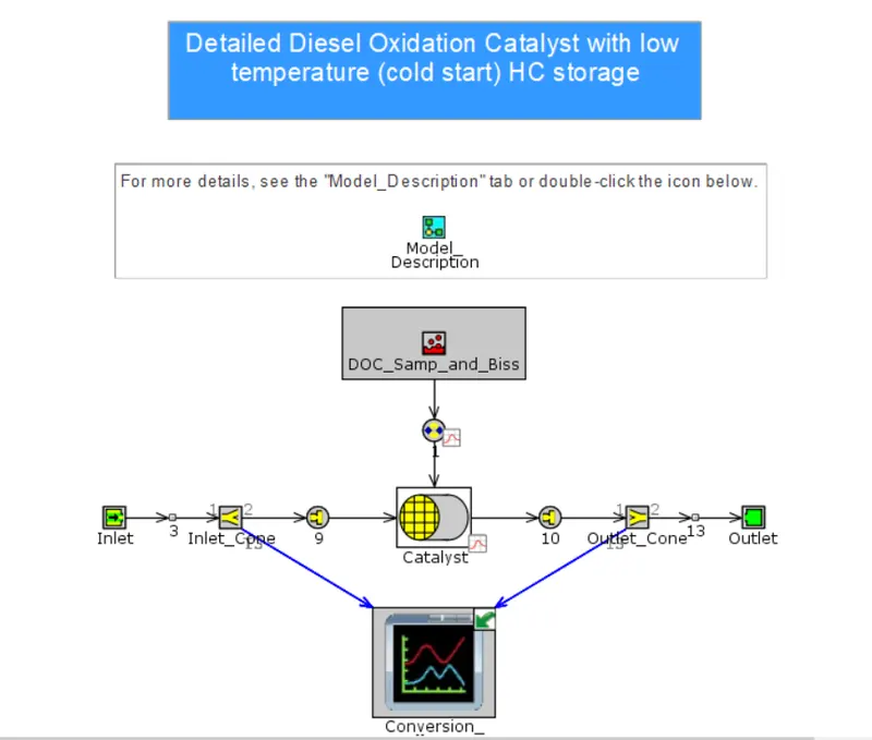
Converssion_Eff_Model:
Building a model:
Inlet:-
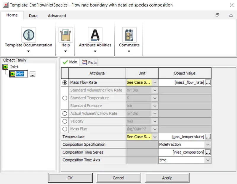
The inlet helps to define the boundary conditions of the flow, temperature and the species composition related parameters. Mass flow rate is the mass of a substance which passes per unit of time. Bascially flow is defined by mass flow rate. Mass fraction indicates that the mass fractions will be used to define the composition of the fluid. Usually composition specification is considered in mole fraction. Composition Time Series helps to provide reference object that defines the composition of the fluid. In this case the composition of the fluid change based on time.
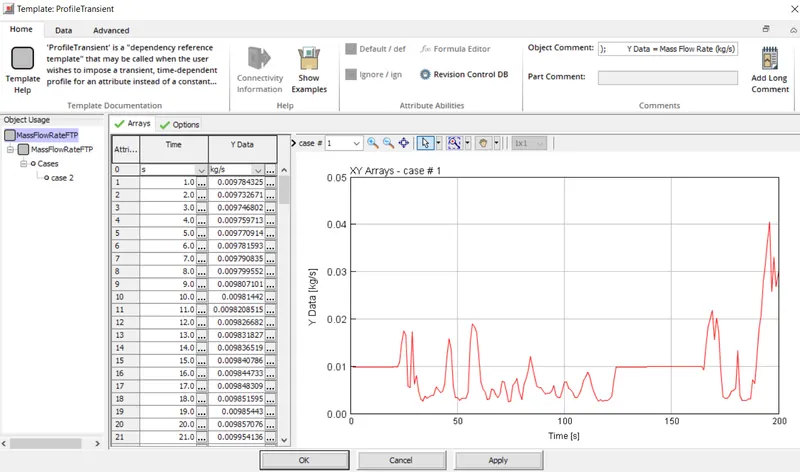
As we have set that the composition varies with respect to time, we need to set the mass flow rate parameter in the casesetup aswell. For the first case directly flow rate is specified and for the second case it is completely dependent on time hence its is specified by "MassFlowRateFTP".
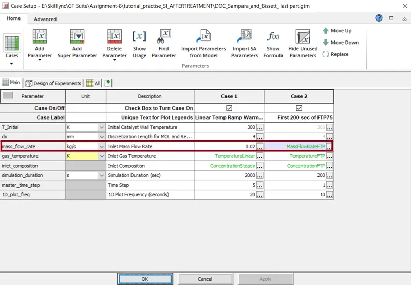
Here, in "MassFlowRateFTP" we can provide reference which can be select when we want to impose a transient, time-dependent profile instead of using a constant value. Hence we call mass flow rate is function of time.
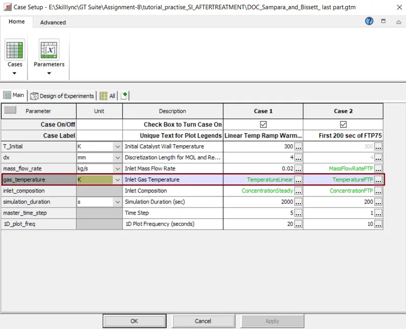
In order to setup gas temperatures in this case for case-1 the demperature is defined as the 'TemperatureLinear' and for case-2 it is defiend by 'TemperatureFTP'.
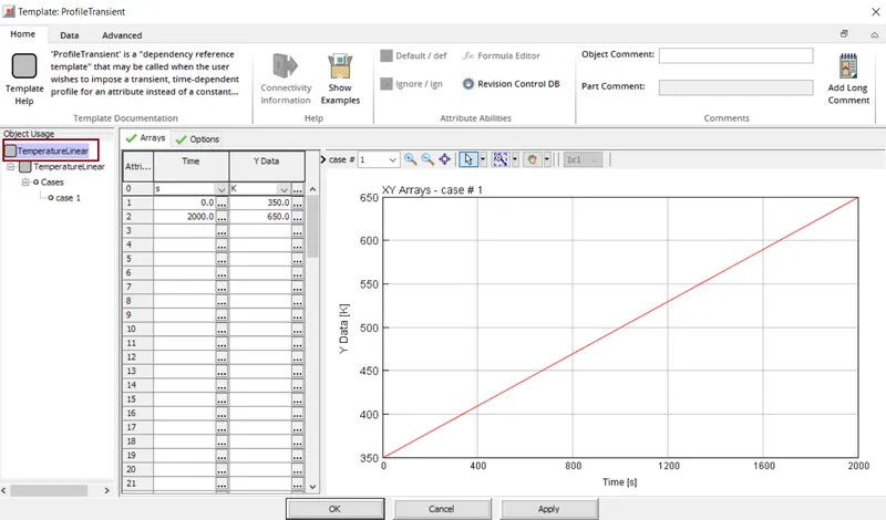
For temperatureLinear, at the time =0sec, the inlet gas temperature is specified as 350K & at time 2000sec the inlet temperature is specified as 650K as a constant value.Both these values are linearly interpolated.
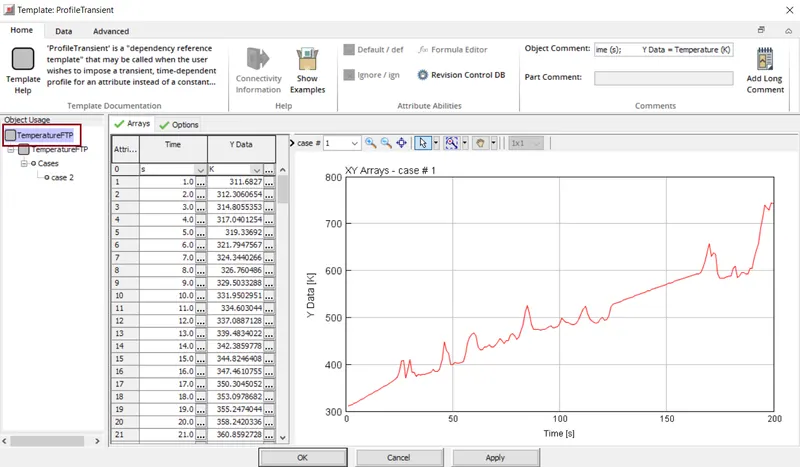
For temperatureFTP, the inlet gas temperatures varies with time as defined in the below table. The plot shows the variation of temperature w.r.to time.
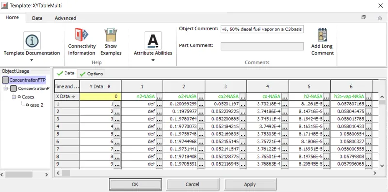
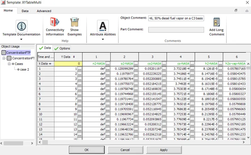
Inlet composition : for case-1Inlet composition is defined as Concentration Steady object and for case-2 inlet composition is defined as Concentration FTPobject.
Catconn_1:-
Inlet_Cone-
Here a flow_split_general template is used to define the flow volume before and after the catalyst. Hence it consists of both Inlet_Cone and Outlet_Cone.
Here, all the basic parameters are specified by the user. volume is set as per the geometry standards. i.e. volume=160000mm^3. The surface area is default and it cannot be changed.
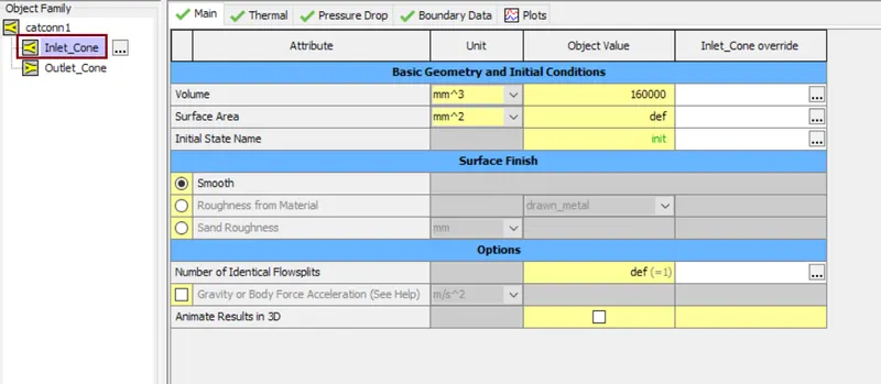
The Initial State Name is given as "init" i.e. this object specifies the initial pressure, temeprature and various fluid properties for the flow components and also can be reffered by the volume.

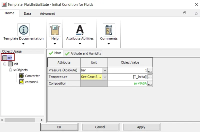
In initial state name we specific the parameters like pressure, temperature and the composition. In some cases we also specify the altitude and humidity.
In this case Pressure is specified as 1bar and for the temperature the object is specified as the fluid temperature at the start of the simulation as a reference.Composition represents a homogneous mixture of one or more liquids or gases.
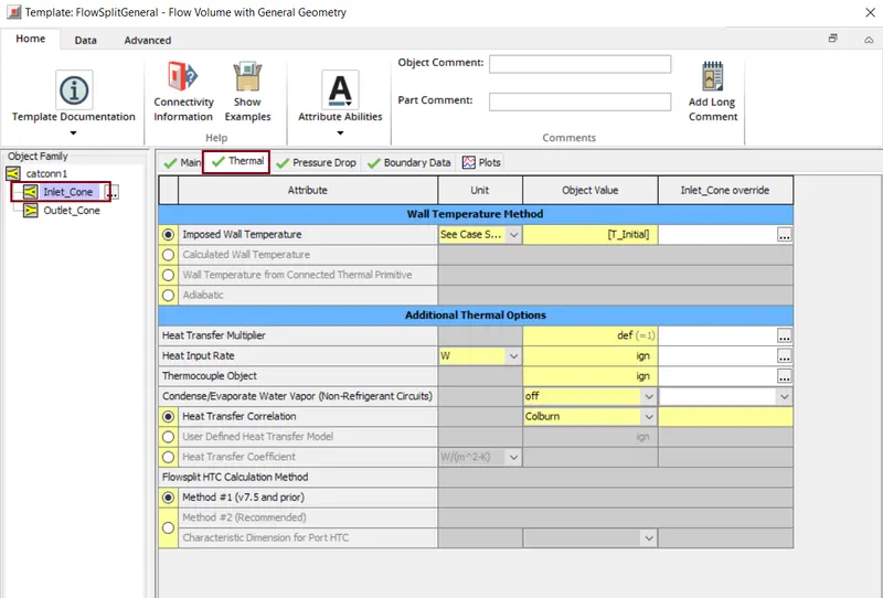
In the Inlet_cone we should also specify the temperatures of the wall surface directly in contact with the fluid. For the imposed-wall-temperature we specify it 'T_inital'.along with the wall temperatures, heat transfer multiplies is considered as 1 for this case. Fo this case Heat Transfer Correlation is specified as 'Colburn' i.e. this calculaets the heat transfer coefficient by choosing the suitable corelations.
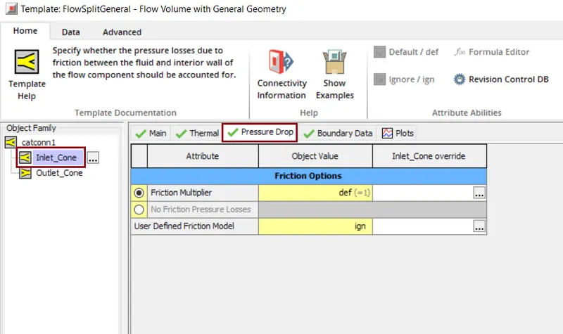
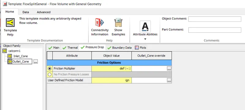
This pressure drop window helps to specify whethr the pressure losses due to friction between the fluid and the interior wall of the flow component.
'Boundary' defines the geometrical information of the port boundaries.Characteristic length is the distance the flow that is entering the boundary will travel before crosing anaothe boundary or the surface. The expansion diameter is diameter to which the flow can expand when entering the boundary.In the 'Adjacent Parts', port-1 is connected to the inlet and the port-2 is connected to catalyst.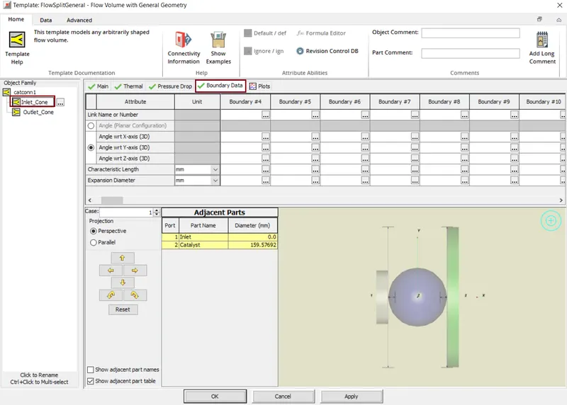
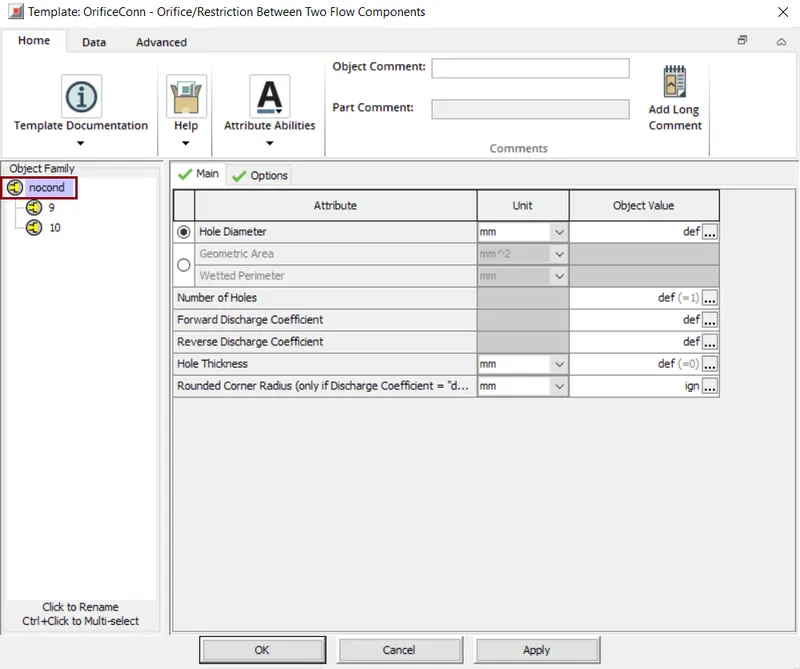
Nodcond(oriffice connection):-
This template models an orifice which is defined by diameter or the areaand the discharge coefficients that calculates the mass flow rate between the adjacent flow volumes.
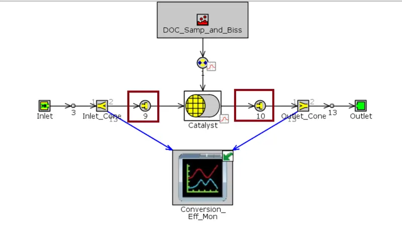
Here, the nocond orifice is used to restrict the conduction heat transfer between the inlet_cone flow volume and the catalyst. The catalyst brick uses the calculated wall temperature method and the inlet wall temperature utilizes the imposed wall temperature. Hence there there there will not be any heat conduction bwtween both the components. The hole geometry parameters are specified here.
Catalyst:-
Any substance that increases the rate of reaction without itself being consumed, this is called catalyst.
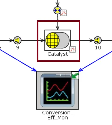
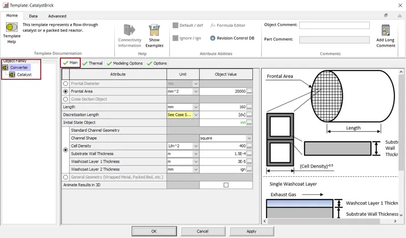
This template represents a flow-through catalyst. Here we can define the basic geometry parameters for the catalyst and also specify the initial conditions. Initially we specify the total front face or crossectional area of the catalyst substrate. The length of the substrate channels are specified here. Following this the initial conditions of the gas inside the catalyst. Also the washcoat layer thickness is provided..
In three ways the wall temperature is provided i.e. by imposing wall temperature, calculating the wall temperature from the material thermal properties and the specified wall temperatures, alos obtain wall temperatures from the connected thermal primitive part.
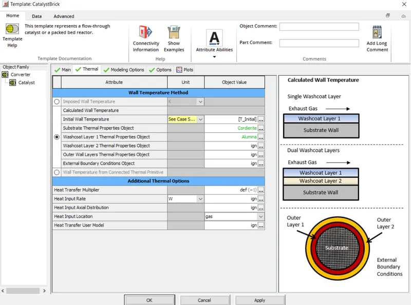
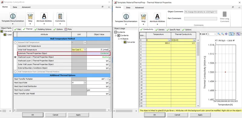
In 'Substrate Thermal Properties Object' we basically define the material properties of the substrate for axial conductivity, density adn the specific heat.AS we specified only one layer, we provide properties for only one Washcoat layer-1.
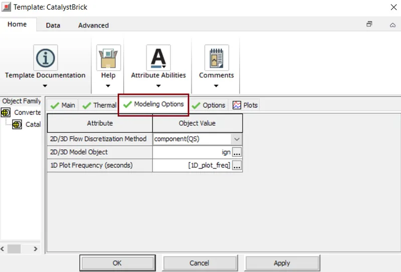
For modeling options, we need to select if it is 2D or 3D only. Here we used flow discretization method as 'component(Qs)', which means a single catalyst will be used for the solution. In the same modeling part we need to specify the frequence for the plot in which data will bestored and reported for the plots listed as 1D which is located in the 'CatalystBrick' part.
Here, the nocond orifice is used to restrict the conduction heat transfer between the inlet_cone flow volume and the catalyst. The catalyst brick uses the calculated wall temperature method and the inlet wall temperature utilizes the imposed wall temperature. Hence there there there will not be any heat conduction bwtween both the components. The hole geometry parameters are specified here.
Outlet_Cone-
Here a flow_split_general template is used to define the flow volume before and after the catalyst. Hence it consists of both Inlet_Cone and Outlet_Cone.
Here, all the basic parameters are specified by the user. volume is set as per the geometry standards. i.e. volume=160000mm^3. The surface area is default and it cannot be changed.
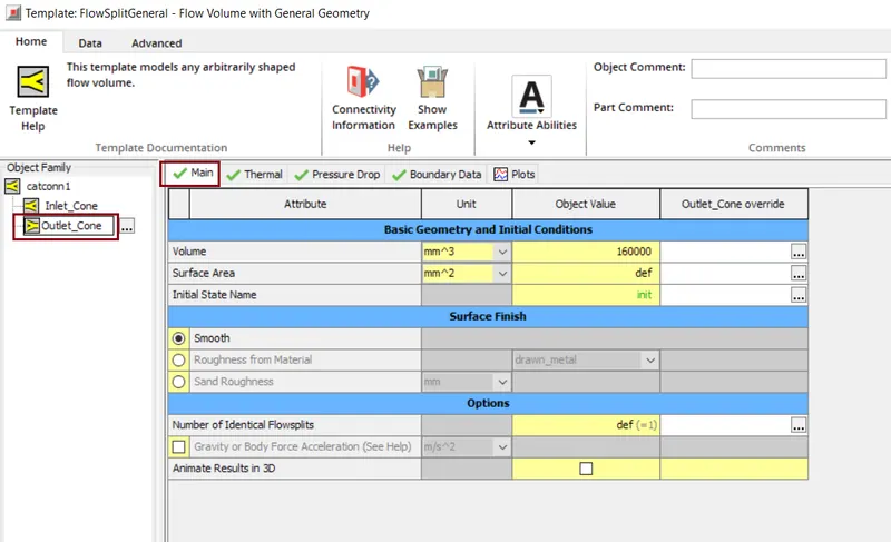
The Initial State Name is given as "init" i.e. this object specifies the initial pressure, temeprature and various fluid properties for the flow components and also can be reffered by the volume.
In initial state name we specific the parameters like pressure, temperature and the composition. In some cases we also specify the altitude and humidity.
In this case Pressure is specified as 1bar and for the temperature the object is specified as the fluid temperature at the start of the simulation as a reference.Composition represents a homogneous mixture of one or more liquids or gases.
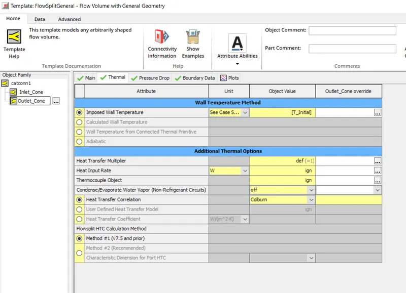
In the outlet_cone we should also specify the temperatures of the wall surface directly in contact with the fluid. For the imposed-wall-temperature we specify it 'T_inital'.along with the wall temperatures, heat transfer multiplies is considered as 1 for this case. Fo this case Heat Transfer Correlation is specified as 'Colburn' i.e. this calculaets the heat transfer coefficient by choosing the suitable corelations.
This pressure drop window helps to specify whethr the pressure losses due to friction between the fluid and the interior wall of the flow component.
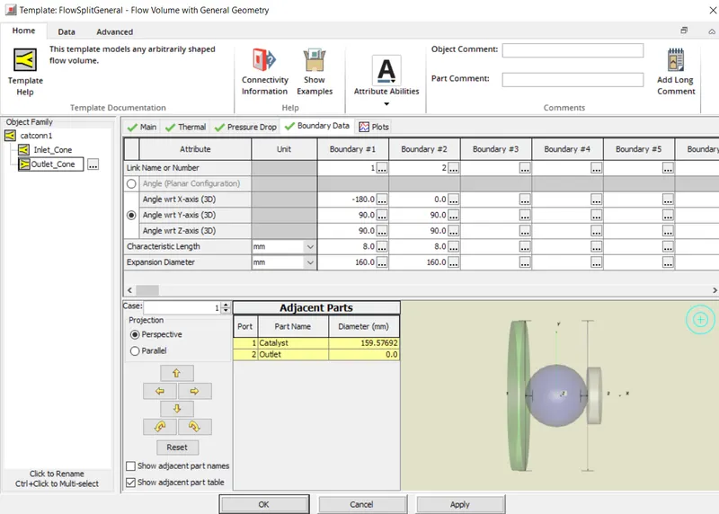
'Boundary' defines the geometrical information of the port boundaries.Characteristic length is the distance the flow that is entering the boundary will travel before crosing anaothe boundary or the surface. The expansion diameter is diameter to which the flow can expand when entering the boundary.In the 'Adjacent Parts', port-1 is connected to the inlet and the port-2 is connected to catalyst.Here adjacent part varies with the inlet. Catalyst value changes and outlet remains zero.
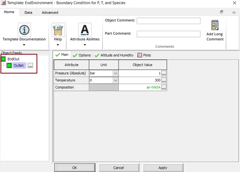
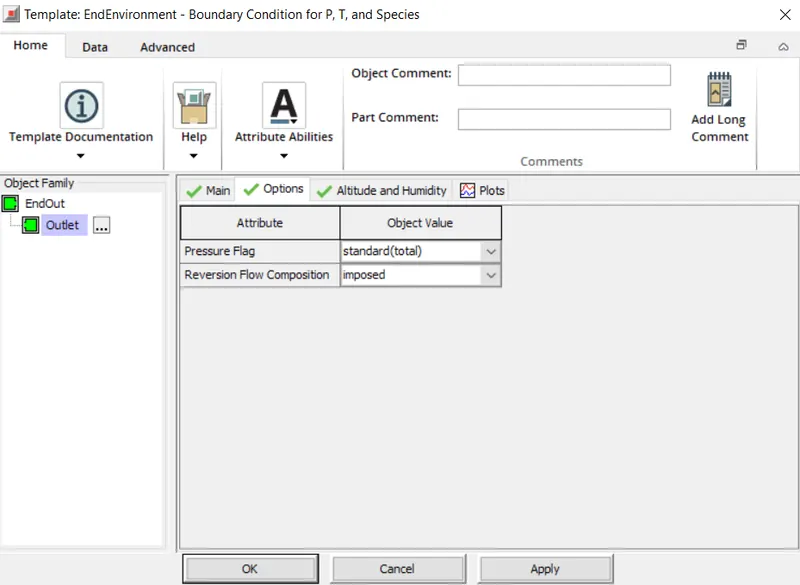
In the EndEnvirinment we declare the boundary conditions of pressure, temperature and composition igf require altitude and humidity is aslo mentioned.
DOC_Samp_and_Biss
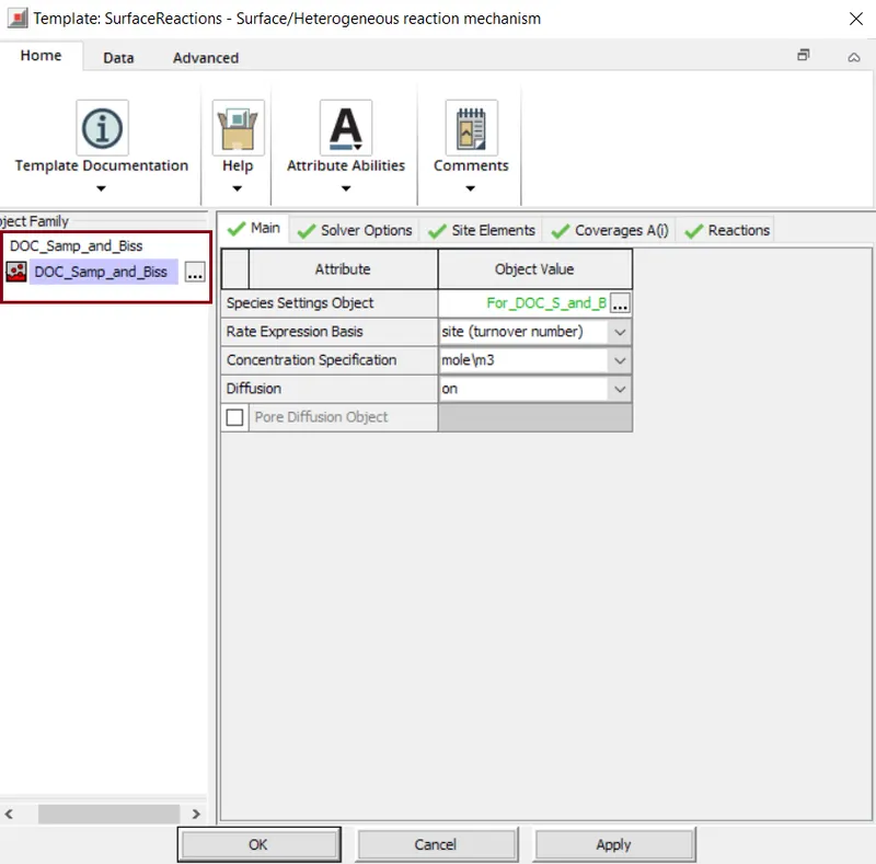
This template specifies catalytic surface reaction kinetics that require the modeling of storage or the coverage.Firstly the species settings are made by selecting ' For_DOC_S_and_B'. Next option we have Rate Expression Basis, here we havethree options to select the basis for the reaction rate. The concentration specification is selected as per the geometry specification.For this we have multiple options like if we consider basis above reactor volume and concentration specification is mole/m3. I f the Diffusion is set ON then it solves the set of equations for diffusion.
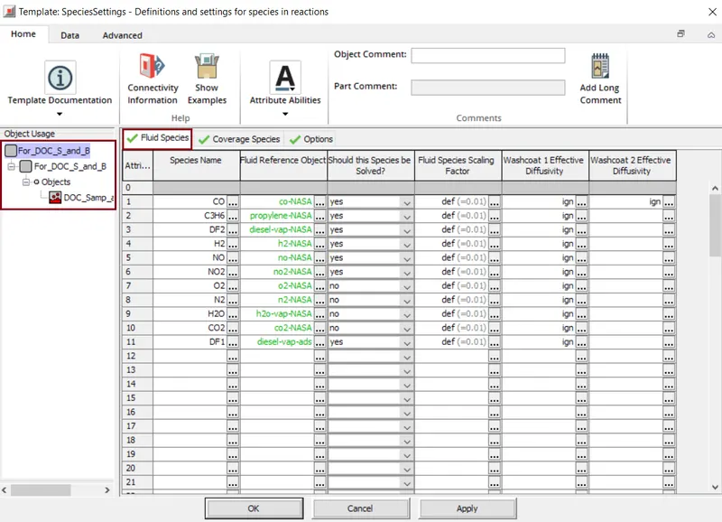
This object helps to map the species that are specified in GaseousReactions, GlobalReactions and SurfaceReactions to the basic fluid objects. For each species the reference objects are alloted and we have to set if that particular species should be solved or not.
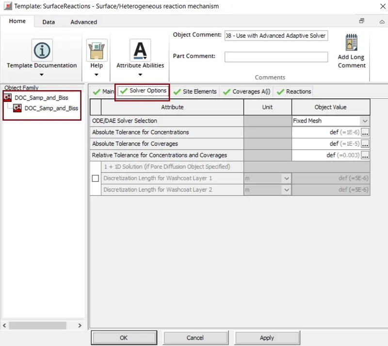
Here we can select solver methods like ODE or DAE solver methods. Advanced Adaptive is a solver method. Rest of the settings are set according to the simulation that we perform.
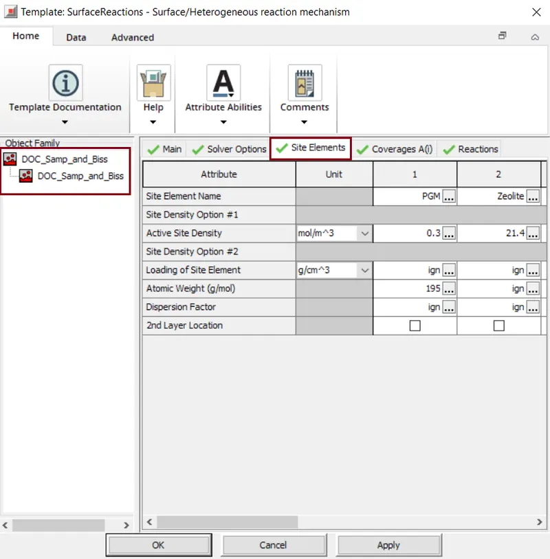
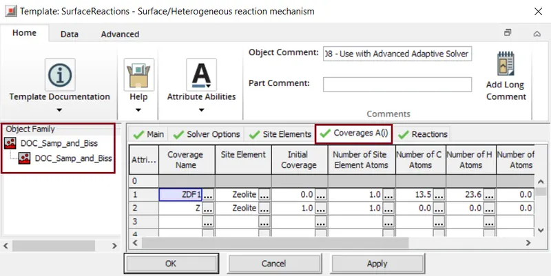
Names of site elements that represent the reaction sites i.e. PGM and Zeolite. Total density of the active sites as number of moles per unit total volume of the reactor . If the density varies along the length of the reactor then the site density can be specified by refering to an XY table where X refers to normalized length of 0-1 and Y is a numeric value. Generally standard atomic weight of the site species in units - g/mol. The dipersion factor is the rationof active sites to total sites. This shows the solver how much of the site element loading is actually available to react.
Coverage Name is nothing but the array of names of the site coverage species. The site element name corressponding to site coverage species.Initial coverage is the fractions of site coverage species. Number of site element atoms in a site species is given by 1.Also number of carbon atoms in a site species are mentioned. The number of hydrogen atoms in a site species is given by 23.6 for 1st attribute.
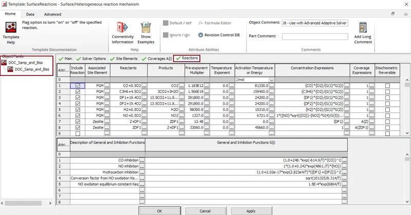
This template specifies catalytic surface reactions kinetics that require the modeling of storage.It contains the information of the chemical reactions taking palce because of the catalyst inside the catalytic converter including the rectants and products of the chemicals reactions, the activation energy required per mol of reactants to form the products and the pre-exponent multiplier and the inhibition functions.
The exponential factor A is used to evaluate reaction rate constant K which is assumed to obey the standard Arrhenius law.
Converge expressions are an array of expressions that specifies the converge terms in evaluating the rate of progress of reactions.
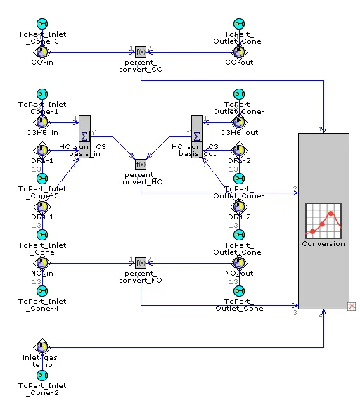
Conversion_Eff_Monitor:
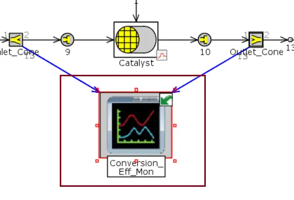
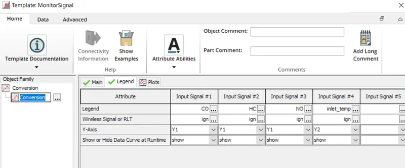
The conversion efficiency monitor is used to monitor the conversion efficiency & the inlet gas temperature during a simulation. The conversion efficiency for 3 types of species are monitored i.e.Carbon Monoxide, Unburnt hydrocarbons, Nitrogen Mono-oxides and inlet gas temperature.
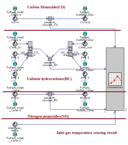
SubAssInternalConn - These are used to define the linking interface from parts in the subassembly to the main subassembly.
SensorConn - This template parts are used to sense the species concentration inside the flow volume like the inlet cone and outline cone.
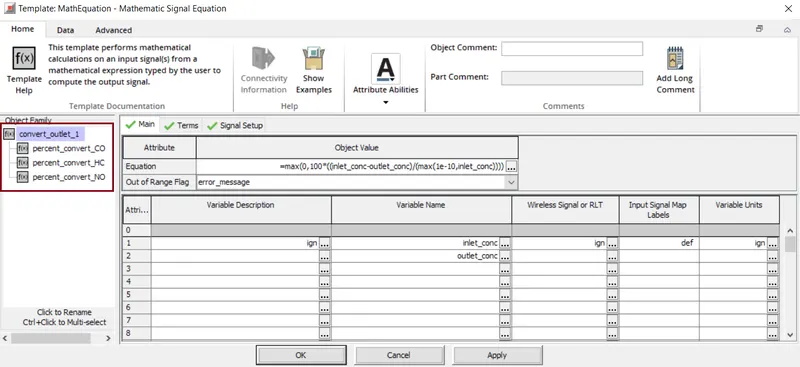
MathEquation(f(x)) - This template part is used to calculate the percentage conversion from the inlet species concentration and the outlet species concentration.
Carbon Monoxide:
The CO in sensors senses the CO concentration in the inlet cone part and the CO out sensor senses the CO concentration in the outlet cone both the sensed signals are sent to Percent_Convert_CO, which later calculates the percentage conversion of carbon monoxide adn sends the signal
Percent_Convert_CO (MathEquation)
Here, this template performs the mathematical calculations of an inputsignals from a mathematical expression typed by the user to compute the output signal.
Percentage conversion=100*(inlet concentration-outlet concentration)/inlet concentration.
Unburnt or partially burnt hydrocarbons(HC):
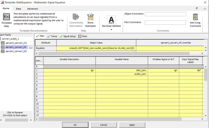
For this part of circuit, three different species are considered as unburnt or partially unburnt hydrocarbons which include propylene-NASA(C3H6), Diesel-vap-ads and diesel-vap-NASA. All the concentration of these species are sensored by C3H6_in, DF1-1, DF2-1 at the inlet cob=ne and the concentration signals are added up by HC_sum_C3_basis_iN.
The output signals fromHC_SUM_c3_basis_in adn HC_sum_C3_basis_Outa are sent to the MathEquationtemplate part percent_convert_HC which calculates the percentage conversion efficiencyof unburnt hydrocarbons.
Nitrogen Mono-oxides(NO):
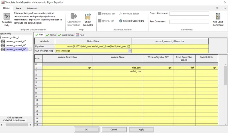
The circuit used for NO is very similar to that for CO. The NO_in sensor senses the NO concentration in the inlet cone part and NO_out sensor senses the NO concentration in the outlet conethen both the sensed signals are sent to percent_convert_NO which then calculates the percentage conversion of carbon monoxide and sends the signal to conversion monitor.
Percentage conversion=100*(inlet concentration-outlet concentration)/inlet concentration.
Inlet Gas Temperature Sensing Unit:
Here the inlet gas temperature is sensed using the inlet_gas_temp sensor adn the signal is sent to the conversion monitor. and this is directly connected to Conversion.
Hence therefore all these are connected to Conversions i.e. it helps to monitoe instantaneous signals or Time RLTs during a simulation.
Conversion:
This part is used to monitor instantaneous signals of conversions efficiency and effect of inlet gas temperature on the conversion efficiency during simulation.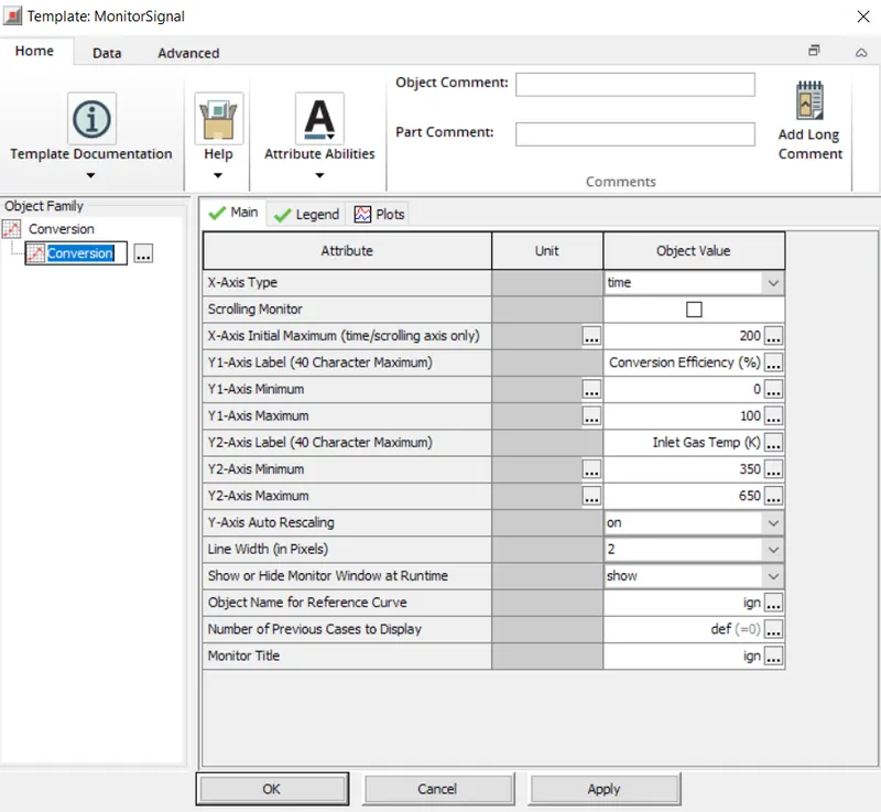
All the required settings are alloted s help to set the legends for the simulation.
Therefore the aftertreatment-DOC-sampara & Bisset model is studied.
Conclusion:
- The difference between Gasoline vs Diesel enginefor various parameters is studied.
- Set of chemical reactions for TWC and SCR from example file is listed.
- Exploring the example model i.e. aftertreatment-DOC-sampara & Bisset.