Assignment 7-Side Pole Crash Simulation Challenge
Objective:
To perform a crash analysis on the side of the given model, also known as a side pole crash. The analysis is to be carried on the deformation and the forces created as a result of the crash at a speed of 35 mph and certain output requests were to be generated and they are as follows:
- Sectional force in the cross members.
- Intrusion at B pillar, hinge pillar, and fuel tank region(Also provide recommendations on what can be done to help reduce fuel tank intrusion)
- Peak velocity of a node on the inner door panel.
SETUP REQUESTS
- Check unit system and either follow [Mg mm s] or [Kg mm ms].
- Create appropriate interface ,friction 0.2 and recommended parameters.
- Make sure of no penetration and intersections.
- Create rigid wall with friction 0.1 as per referance model.
- Compare the model weight with the referance model and use added masses to reach target weight 700kg while getting CG about the required range.
- Initial velocity as shown in picture.
- Use model checker to ensure good quality.
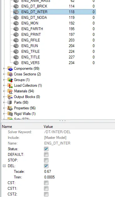
- Timestep :0.5 to 0.1 microseconds.
- Run 80ms.
- Run the analysis
PROCEDURE:
We will be using Hypercrash and Hypermesh to set up the model. Some checks will be done in Hypercrash and some in Hypermesh. First, we will import the model into Hypercrash and check for Penetration and make sure the units are in Kg mm ms.
The unit check can be done without opening the model. We can just open the Neon_front_0000.rad in a notepad where we will be able to check the units.
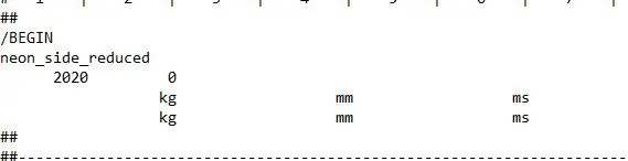
We can see that the Units are in Kg mm ms. Now we will open Hypercrash and perform a penetration check and also will be adding mass to the body.
To open hyper crash we have to first open hyper mesh.
Now go to Application >> hyper crash>> Select the unit system >> open
Once Hypercrash is opened we will be checking for Penetration and Intersection.
Penetration is defined as the overlap of the material thickness of shell elements, while Intersection is defined as elements that actually pass completely through one another.
All models and especially impact models should be checked for penetrations and intersections to make sure there is no penetration and intersection. Penetrations adversely affect results and should be removed.
To check penetration and intersection
Got to Quality>> Check Intersection on tree >> Select parts > Click on check penetration
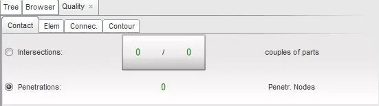
We can clearly see from the above figure there are no penetrations and intersections are present in the model.
COG and Additional Mass:
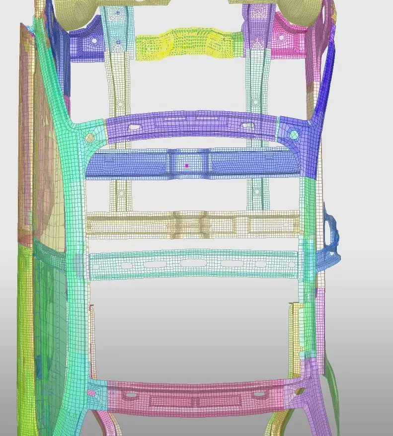
In the next step, we will be adding masses to the setup. Since this is a reduced model the vehicle's weight and COG are not at the required point. So we will be adding some masses keeping the full model as a reference and will be bringing the COG at the required point.
The reduced model's weight while importing was 166kg so we will be adding massed to bring it up to 700kg in the appropriate places so that the COG is at the center of the model betweent the seats
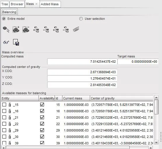
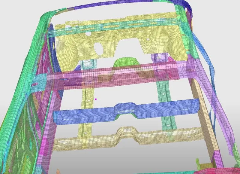
Once the Additional masses are added we can see that the total weight is 700kg and the correct position of the COG.
Export the changes made in the Hypercrash and import the same file in Hypermesh to make other changes.
Go to File >> Export >> RADIOSS
Now import the same file in hyper mesh to do other changes. So open the imported .rad file and we can start with providing the connections.
Type 7 contact
Type-7 Node to surface contact is used in this model. Both the Slave nodes and the Master nodes will be the same for this simulation since there is self-intersection between the parts while it simulates.The recommended properties are as follows
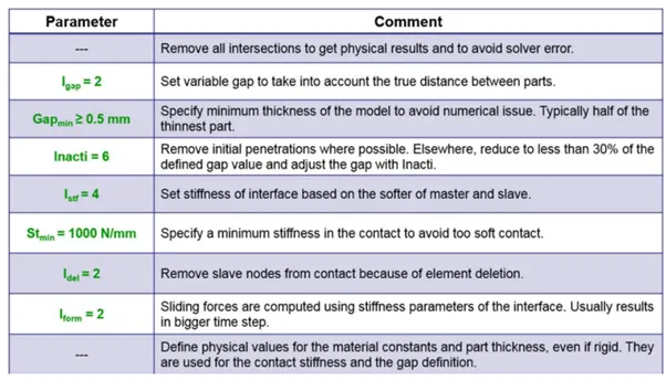
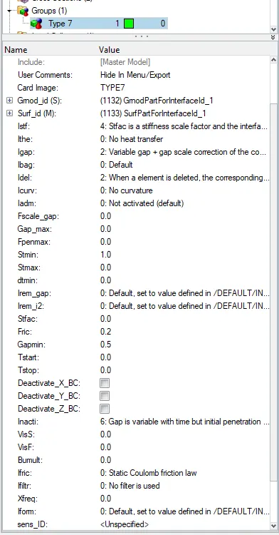
Delete the other contact groups.
RIGID WALL:
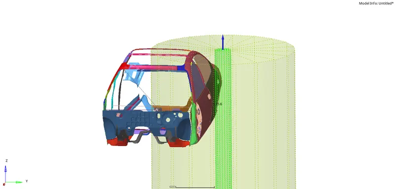
A rigid wall is a nodal constraint applied to a set of slave nodes in order to avoid the node penetration to the wall. If contact is detected, then the slave node acceleration and velocity are modified. Mainly to constrain the movement of a moving body after impact, we will be using a plane wall. An infinite plane wall is a plane that extends to infinity. It is defined with two points.
Rigid wall entities provide a method for treating a contact between a rigid surface and nodal points of a deformable body. In the Radioss user profiles, rigid walls can be created in the Model and Solver browsers.
To create an RWALL
Go to Solver browser >> Create >> Rwall >> Cylindrical
We need a reference node to create an RWALL so we can select a node at the outermost part of the side door
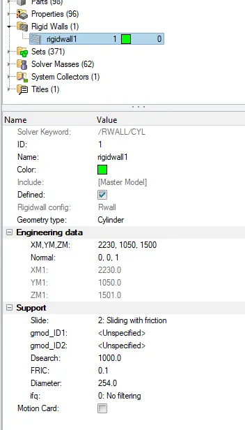
Then we will give the normal direction to the pole in the Z-axis and diameter of the pole to be 254 mm. The FRIC value will be 1 and Dsearch value will be 1000 as shown above.
INPUT VELOCITY:
The velocity input for this simulation as per the Standards is 35mph so when we convert it to m/s the input velocity is 15.6464m/s.
To create initial velocity
Go to solver browser >> Create >> boundary conditions (BC) >> Inivel
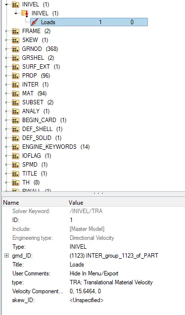
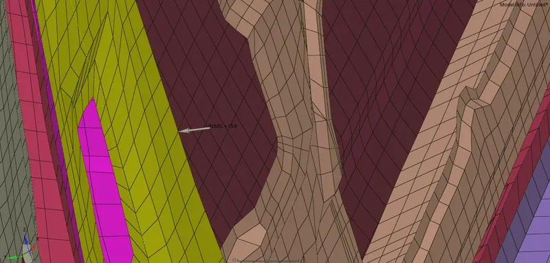
Define the Node group on which specified initial velocities are applied (grnd_ID1). For our simulation, we will be selecting the whole vehicle setup.
The velocity type is selected as Translation velocity and it is provided in the y-direction .
CREATE SECTIONAL FORCES:
We need to Create Sections at Cross members
We should know how the forces are transmitted from the side door to cross member and the rate of deformation. It is done in order to ensure the safety of the passenger.
Certain components will crash (deform) more than the other so that the forces are distributed correctly leaving very little force left to transmit inside the cabin.
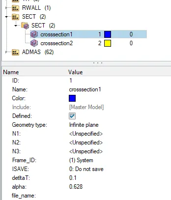
To create a section and Frame Go to Slover browser >> Create >> Section >> SECT
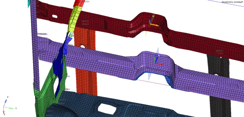
FRAME CREATION:
Before creating sections, we should create frames. The Frame is created to make local coordinates of the section.To create the Frame, Right Click on the Tab Area in the Solver Browser >> Click Create >> FRAME >> MOV >> Select the Nodes So Create an Axis >> Create.
Remember, while creating local coordinates, select the nodes in such a way that the Z- Axis should be in the direction of the initial velocity applied
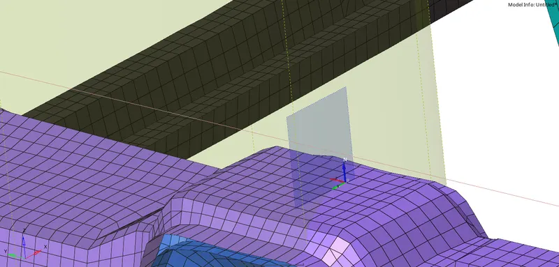
Now create sections and assign each FRAME to each Section accordingly , grshel_id select a section of elements on a component where we should calculate forces going through them.
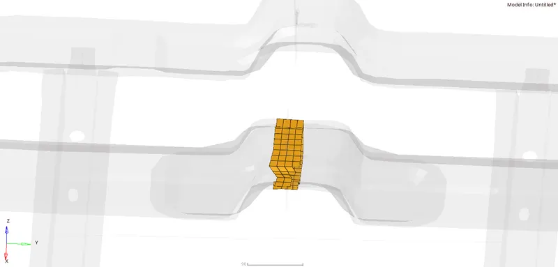
Remember, the plane created at the section must be perpendicular to that component.
INTRUSION SPRINGS
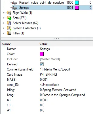
Here, we need to find the intrusions at B-pillar, hinge pillar and fuel tank. So to find the results at the specified parts, we need to create spring between left and right parts of B-piller, Hinge-piller and fuel tank, for creating spring go to 1D -> SPRINGS -> SPRING2 and select 2 nodes
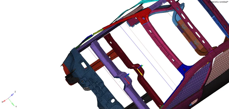
Create a property, a new tab will open there we have to select CARD image as P4 SPRING and Mass as .001, and Stiffness as 0.001, Assign this property to the springs
Peak velocity of inner node of the door:
To find peak velocity at the inner node of the door, we will create a moving frame at the node location by using right-click on solver browser -> create -> skew -> MOV.
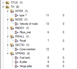
Delete existing TH and Create New Cards
Delete all the unnecessary TH files and create the Time History files for the boundary conditions that we have created for the frontal crash model.
This will help us reduce some time for simulation as the solver only calculates TH for required outputs
Edit Cards:
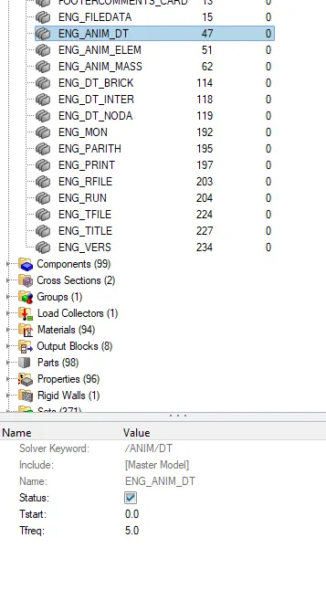
Before running the simulation check all these cards and assign the values accordingly
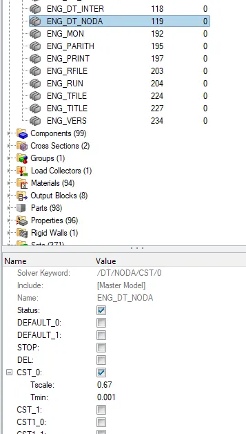
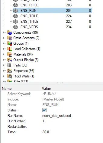
CHECKS:
These checks can be done via both Hypermesh and Hypercrash but it is recommended to check via the Hypercrash module. Before exporting the model we will be checking for Unused and Empty, make sure all the parts are connected, or once the simulation is done the results will be wrong with parts flying.
Tools>>Unused and Tools>>Empty and delete the unwanted data in the model and export them.
The Model checker will give us any warnings and Errors regarding the model definition and, the boundary and Kinematic conditions, etc.
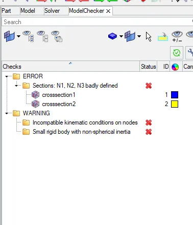
- Boundary Condition is not defined properly
- Incompatible Kinematic Condition
- The Part Property or material is not defined properly, etc.
- We can avoid the Warnings as the solver will automatically autofix
But we must fix every Error in order to get a successful simulation free of problems
RUN THE ANALYSIS:
Analysis >> Radioss >>save file >> select Radioss
The h3d file and T01 file will be saved in the same folder.
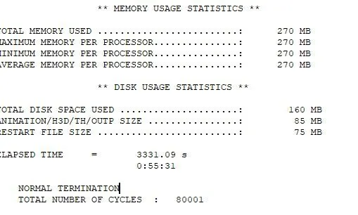
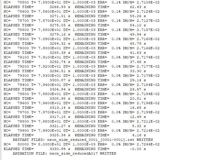
As we can see, the energy error is 0%. It is acceptable due and in addition to that, the mass error is 2.7E-02, which is less and acceptable.
Total Simulation Time: 55mins
Total Number of cycles: 80001
To view the simulation, we can switch to Hyperview anf for graphical representation switch to hypergraph 2D.
DISPLACEMENT CONTOUR PLOT:
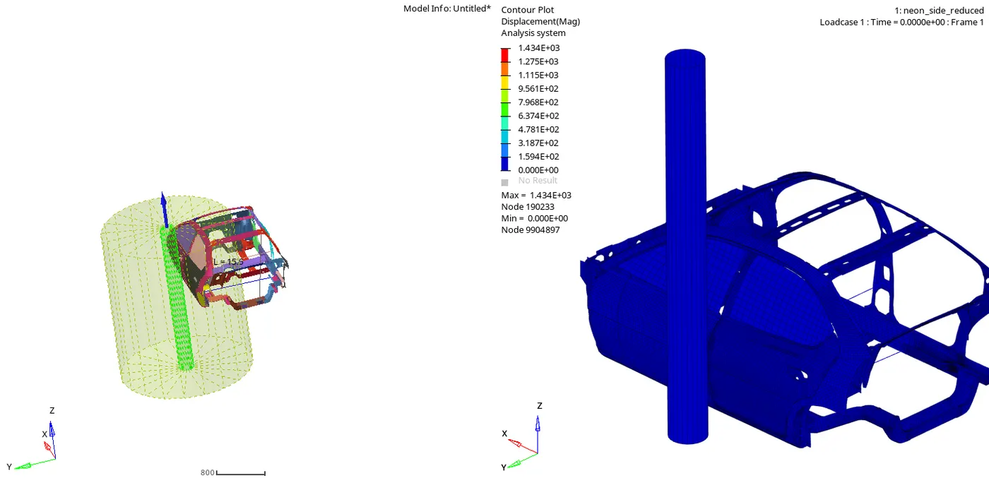
In the above simulation the vehicle BIW is impacting on a Pole. After the impact, the frame of the vehicle deforms and the vehicle body gets contracted around the pole with left B-Pillar as the pivot point. The CG of the vehicle is in the same axis or direction of the pole, so we can see even deformation of the frame around the pole.
VON MISES CONTOUR PLOT:
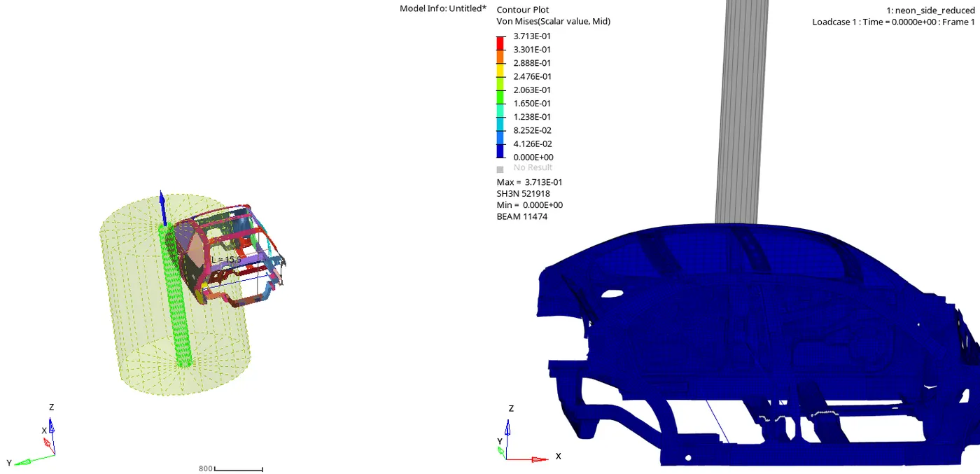
In Von Mises stress plot, t the stress distribution is good in the vehicle after the crash. There are very few areas where there is stress concentration. Generally, the stress is more in B-pillar and cross members as B-pillar takes the initial impact and then the impact is transferred to the cross members.
ENERGIES
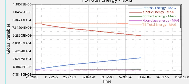
The changes in kinetic and internal energies occur at the exact moment the BIW contacts the rigid cylindrical wall, the BIW loses kinetic energy throughout the simulation due to the obvious decrease in velocity and it absorbs the forces, and this results in an increase in internal energies, and as a result, the deformations also occur.
Contact energy is a type of energy that is formed when one element meets the other or neighboring elements. The opposing force created by this element forms the contact energy. It increases after 7 ms, at this point the model starts deforming in such a way that penetration of nodes occurs.
The increase in contact energy affects the overall energy of this system, which is why there is a decrease in the total energy over the course of the simulation . The magnitude of contact energy generated is much lower compared to that of the energies in the previous plot.
From the above graph, we can see that the Hourglass energy is almost negligible since we have used Improved integrated element formulation (QEPH).
RWALL FORCES
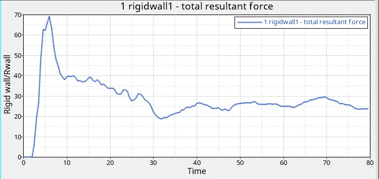
Rigid wall force generated is zero till 2 ms of simulation because of no contact, but at the 6 ms there is a peak rise in the wall forces to a value of 68KN which is the point of the first impact, Then rigid wall force decreases and stabilize to a constant value as it progresses.
SECTIONAL FORCES
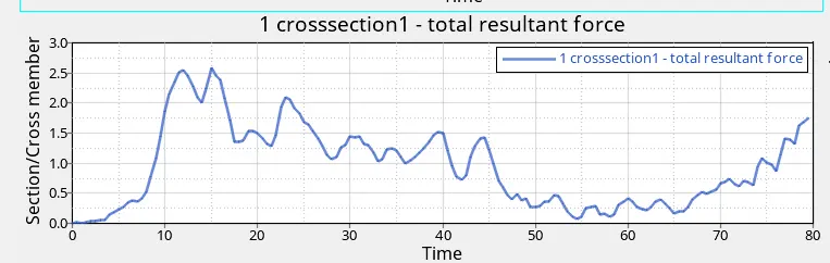
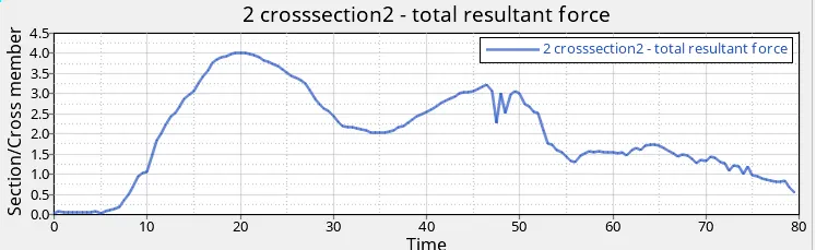
Cross-members are important in the side-impact analysis as these components prevent the body to shrink or deform . When the car hits the rigid body maximum amount of forces will pass through the cross member of the base and roof. The maximum force on the 1st crossmember which is in front with driver seat 2.6KN and at the cross member behind it is 4KN
PEAK VELOCITY AT NODE IN DOOR
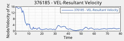
The initial velocity of the car is 15.64 m/s As the car impacts on the pole there is sudden drop in velocity. the decrease in velocity is due to decrease in kinetic energy . Due to collision there is increase in velocity in the maximum velocity of 16.21 ms/s and then it its start decreasing
INTRUSION INSIDE THE CAR AT B-PILLAR, HINGE PILLAR, FUEL TANK
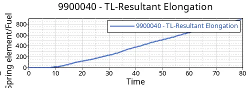
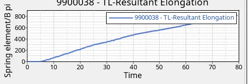
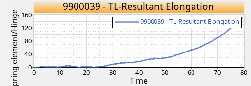
The purpose of intrusion to know the displacement of the node in the occupant area.
The intrusions is minimum at the hinge pillar at 150mm
The Intrusion at the B-pillar is maximum compared to the other two intrusions which may harm the passenger and the intrusion in the fuel tank 800mm will definitely damage the fuel tanks causing a leak
These intrusions can be avoided by adding another Cross Member at the fuel tank, which can withstand load and avoid too much load acting on the fuel tank
CONCLUSION
The given model was simulated for the side crash using Radioss and the results obtained were observed. The graphical results were plotted for all the test cases.From all the results it is seen that the cabin is mostly deformed which can be avoided by providing additional cross members at top and bottom.
T01 FILE LINK
https://drive.google.com/file/d/1OgSLSjSKaO-Li40X0qGXpm3GobbtIE7M/view?usp=sharing