Assignment 7-Side Pole Crash Simulation Challenge
Aim :-
Perform side pole crash simulation of the given vehicle front body using Hypermesh Radioss solver.
Procedure :-
1. Import the 0000.rad file into the hypermesh with Radioss profile.
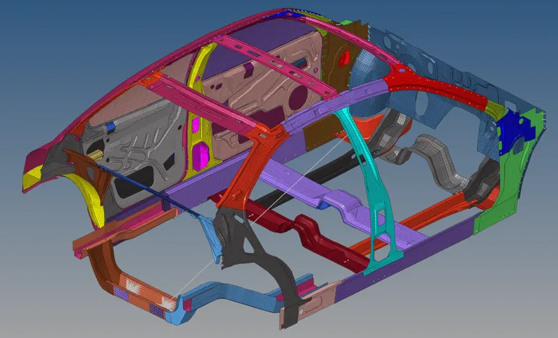
Fig 1 :- Model Imported
2. Check for unit system by Model browser->cards->Begin Card.
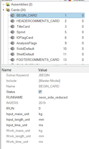
Fig 2 :- Unit Check
3. Type7 contact is created with recommended properties and friction = 0.2, Include all 95 components for slave and master.
Solver Browser->Inter->Right Click->Create->TYPE7
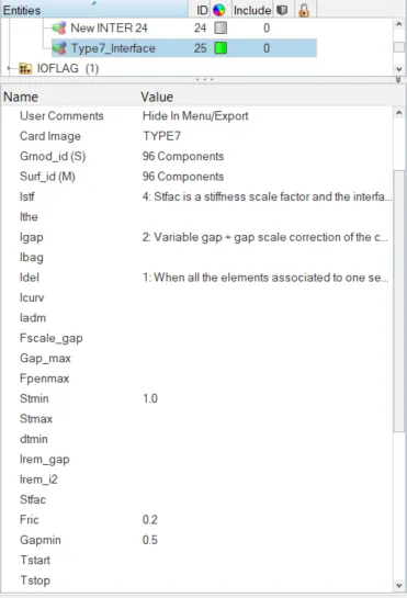
Fig 3 :- Type7 Contact Creation
4. Check for penetration and intersection by Tools->Penetration Check->Intersection and Penetration->Select all the components->Check.
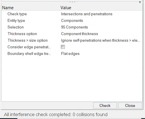
Fig 4 :- Penetration Check
If there are any issues with the penetration, then fix them using appropriate commands.
5. Create rigid wall by Solver deck->Right Click->RWall->CYL. Select the outermost node on the side door and offset towards the Y-axis to maintain the gap.
The sliding friction should be 0.1
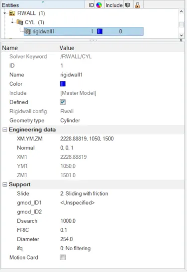
Fig 5.1 :- Create rigid wall
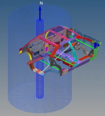
Fig 5.2 :- Rigid Wall Created
6. Check for center of gravity by Tools->Mass Details->Mass, COG and Inertia. Initially mass is around 166Kg and CG is not at the desirable point.
Add mass at appropriate points to get upto 700kg and CG at desirable point.
Solverdeck->Right Click->ADMAS->Select the nodes to add mass->Enter mass value.
Addition of mass will be as follows,
| Component | Mass in KG |
| Fuels tank Support Left | 30 |
| Fuels tank Support Right | 30 |
| B-Pillar Beam | 60 |
| Seat Cross Section | 90 |
| Driver & Seat | 70 |
| Passanger & Seat | 70 |
| Leg Space Left | 55 |
| Leg Space Right | 55 |
| Dashboard | 73.69 |
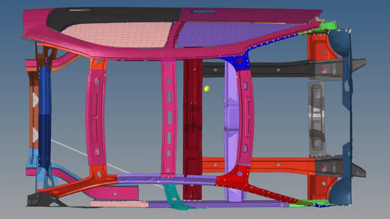
Fig 6.1 :- Initial COG
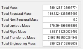
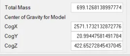
Fig 6.2 :- After mass addition Fig 6.3 :- COG After mass addition
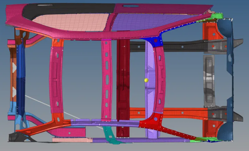
Fig 6.4 :- Desired COG
7. Create a initial velocity card by Solverdeck->Right Click->Create Inivel->Select all the 95 components.
35 mph can also be entered as 15.656 mm/ms to match our unit system.
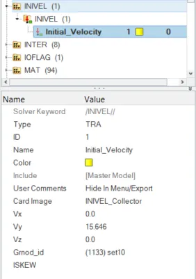
Fig 7 :- Initial Velocity Card
8. Check the quality by Tools->Model Checker->Radioss Block. Run the checker and if there are any issues then auto fix the issue.
9. Set up the time step by going to Model Browser->Cards->Eng_Anim_Dt->Tfreq=5.
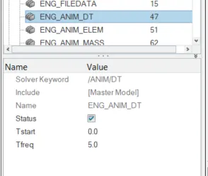
Fig 8 :- Time step
10. Enter the run timing by Model Browser->Cards->Eng_Run->Tstop=80.
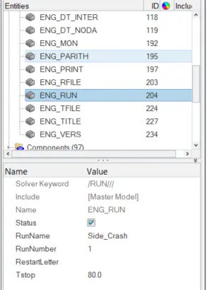
Fig 9 :- Run Time
11. Create Sections for the following components by Solver browser->Right click->create->Frame->MOV.
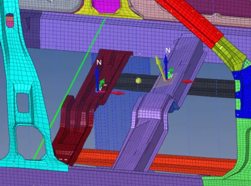
Fig 10.1 :- Creation of Moving Frame card
After creating the moving frame, create sections by Solver browser->right click->create->SECT->SECT.
Specify the Frame_ID with the created moving frame, alpha=0.6 and detla=0.1
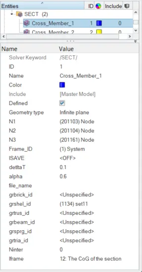
Fig 10.2 :- Section Created
12. Create Intrusions on the Fuel tank support, B-Pillar & Hinge Pillar.
Initially create spring elements by 1D->Springs->springs2->Node Selection. Assign a new property as shown in the snap for spring element.
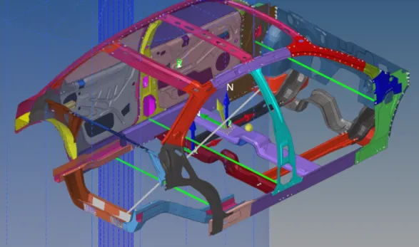
Fig 11.1 :- Spring element shown in Green Lines
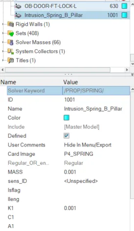
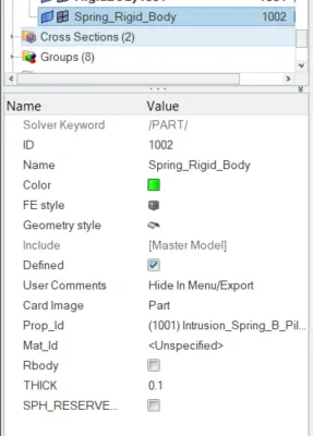
Fig 11.2 :- Property Card for Spring Fig 11.3 :- Property Assigned to Spring
13. Create output blocks for Cross Sections, Fuel Tank Support, B-Pillar, Hinge Pillar, Peak velocity & Sectional Forces.
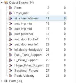
Fig 12 :- Output Block
14. Run the analysis by Analysis->RADIOSS->Save as 0000.rad->Enter "-nt 4" in options->check incluse connectors->Radioss.

Fig 13.1 :- Analysis Set up
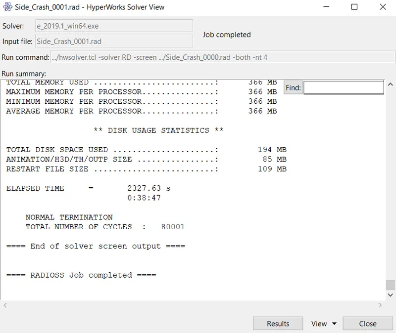
Fig 13.2 :- Analysis Completed
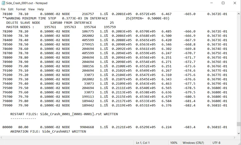
Fig 13.3 :- Analysis Output
- Energy Error :- 1.1%
- Mass Error :- 0.3681E-01
- Total Run Time :- 2327.63 s (38:47 min)
- Total No. of Cycles :- 80001
15. Open Hyperview to view the simulation of crash. Apply the .h3d file from the output generated by simulation.
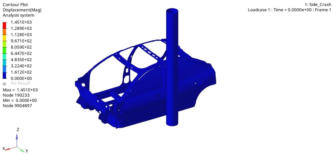
Displacement After Side Pole Crash
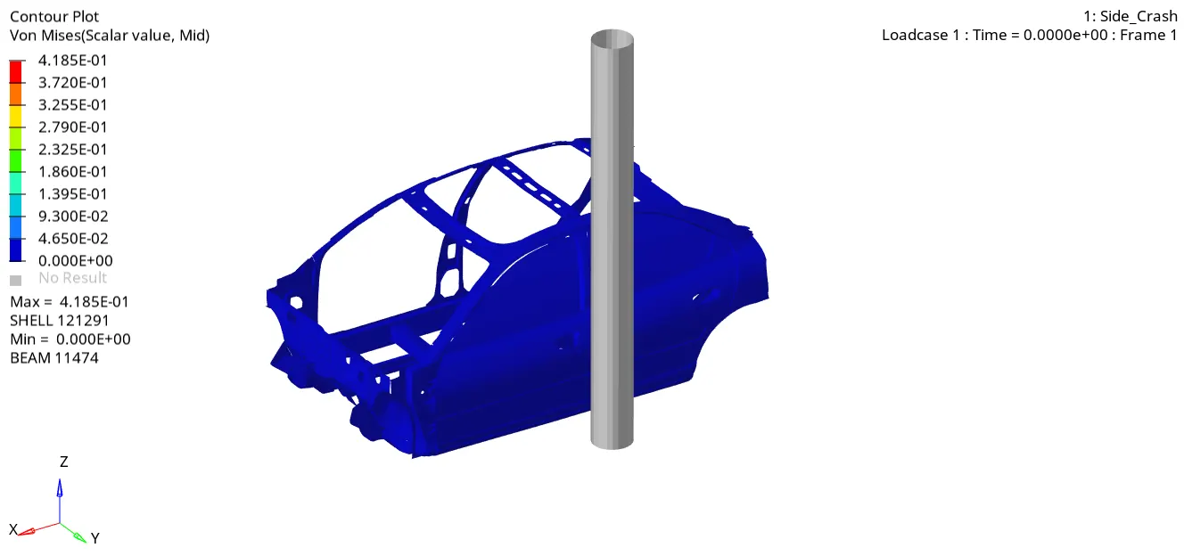
Von Mises Stress After Side Pole Crash
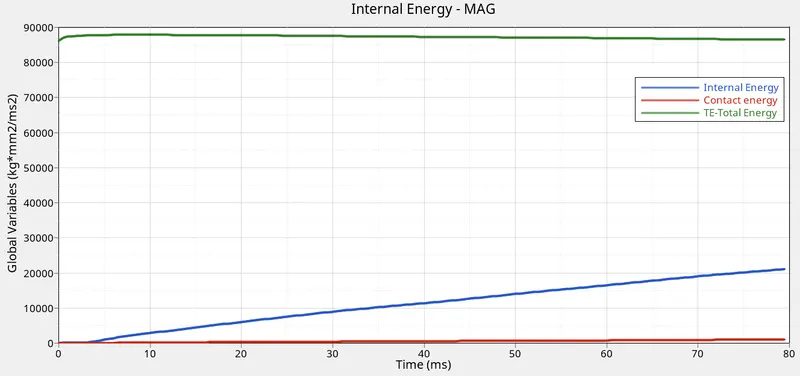
Energies During Side Pole Crash
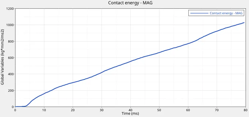
Contact Energy During Side Pole Crash
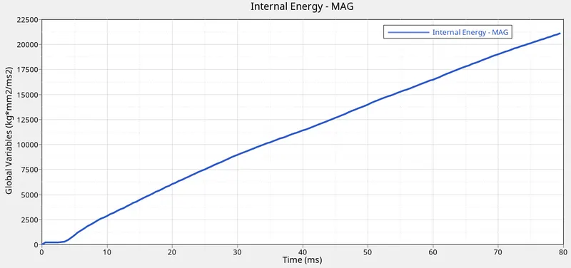
Internal Energy During Side Pole Crash
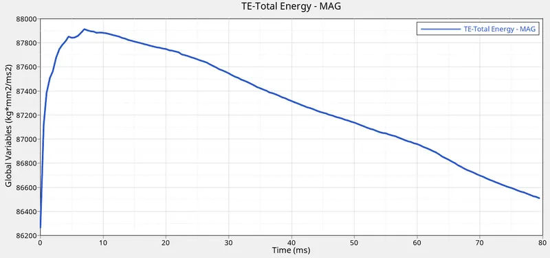
Total Energy During Side Pole Crash
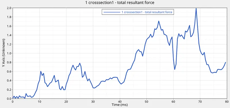
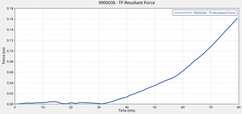
Total Resultant Force at Cross Section-1
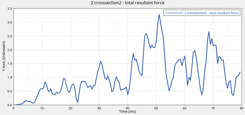
Total Resultant Force at Cross Section-2
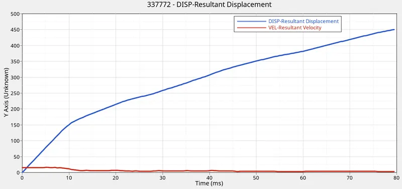
Peak Velocity During Side pole Crash
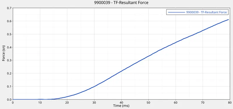
Intrusion at Fuel Tank
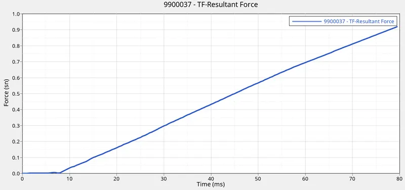
Intrusion at B-Pillar
Intrusion at Hinge Pillar
Result :-
The given vehicle model is simulated for side pole crash using Hypermesh with Radioss solver and the animation, energy plot, intrusion plots are represented above.
By observation, it was found that the deformation was maximum at the center of the vehicle body. Since the impact is effecting the center, it is very important to note that the driver and passanger seats will be under risk.