Assignment 7-Side Pole Crash Simulation Challenge
AIM: To test a vehicle crashworthiness by performing a side pole crash analysis and analysizing the results using RADIOSS
OBJECTIVE: performing operation in the present project
- Check unit system and either follow [Mg mm s] or [Kg mm ms].
- Create appropriate interface ,friction 0.2 and recommended parameters.
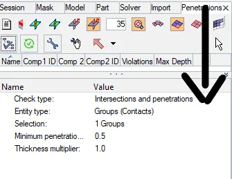
- Make sure of no penetration and intersections.
- Create rigid wall with friction 0.1 as per referance model.
- Compare the model weight with the referance model and use added masses to reach target weight 700kg while getting CG about the required range.
- Initial velocity as shown in picture.
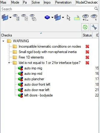
- Use model checker to ensure good quality.
- Timestep :0.5 to 0.1 microseconds.
- Run 80ms.
Output requests:
- Sectional force in the cross member.
- Intrusion at B pillar,hinge pillar and fuel tank region.Provide recommendation on what can help to reduce Fuel tank intrusion.
- Peak velocity of inner node of the door.
lets do this project in two sets as necessary BCS and output requests
PROCEDURE:
- import the model from the slover deck
- check the model and get a proper view of all the connections and components
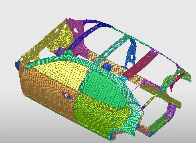
1.creating a interface:
- we have to create a interface among the components by defining them as slaves and masters
- as the body is crashing onto the pole .e, a rigid body all the components are defined as slaves and masters, steps as follows
- MODEL>--CREATE>--CONTACT>--TYPE-7
- GIVE all the 95 componenets as both slave and masters nodes
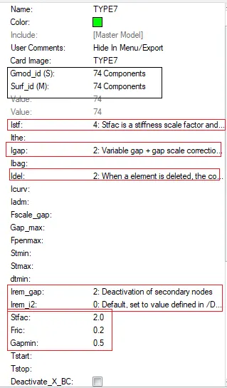
- set all recomanded properties and defime the contact
PENETRATION CHECK:
- after defining the contact we have check for the penetrations and intersections, these arise because of the improper paramaters
- TOOLS>--MODEL CHECKER>--GROUPSl>-- run check
R-BODY CYLINDRICAL POLE:
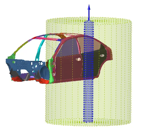
- we have to createa rigid body so as to make a crash on to it
- as of previous project we have defied walla as rigid rody where as now we are usig a pole
- MODEL>--RIGIDBODY>--type as CYLINDER> CREATE
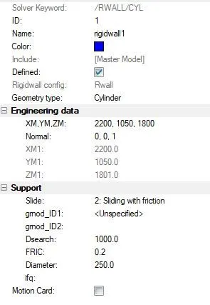
- all the parameters are to be set in as given here, search distance=1000,friction=0.2, diameter of pole as =250
- define the coorfinate point , at the side of the car as shown and define the the normal accoyding to the direction of the crash
MASS ADDITION AND COG IDENTIFICATION:
IT is asked to Compare the model weight with the referance model and use added masses to reach target weight 700kg while getting CG about the required range
so, we have to firstly know the mass of the present model then locate the cog. then the weight should be increased to 700 kg as asked
- TOOL>--MASSCAL>--select the components>--calculate
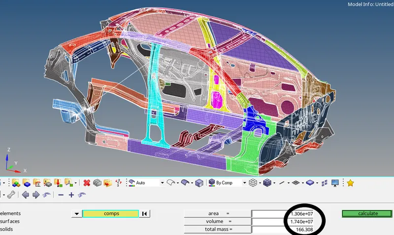
- corresponnding cog of the car body is as given
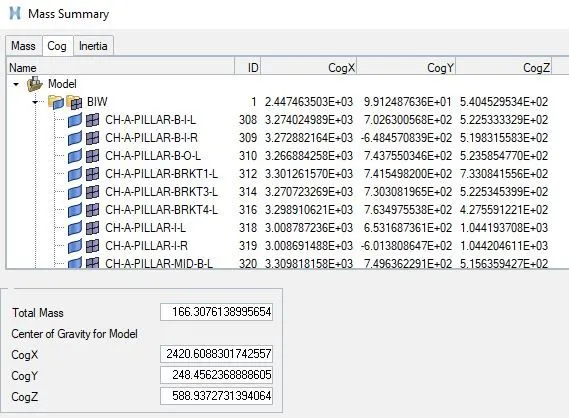
- from the above figures, we now know that the weigh =166.6kg and COG cordinated
- now we should increase the weight 700ky by using admass, before doing so we have to provide the sets
SETS:
- these are manual defined groups , easily saying these form a group of nodes, elements etc defined by the user so as to use them in the future function calling
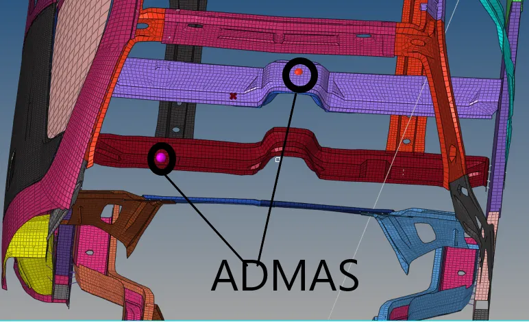
- SLOVER>--ADMAS>--CREATE>--select the sets as assmass1 and admass2
- in ADMAS card change the mass value , see that the distribution of mass is s "0"
- by trail and error method make the weight to 700kg, also locate the new cog
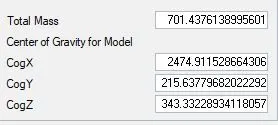
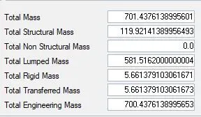
- the location is as shown, as this cog is not on the elements node will not appear , so create a point
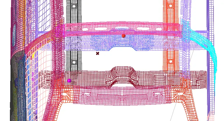
- also, location of the mass sets as shown in the figure below, we can aggange these mass any where mostly see that it is as per the standed cog of fmvss standeds
INITIAL VELOCITY:
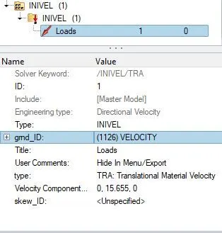
- for the crash to happen , some amount of velocity has to me given to the vehicle
- as per the fmvss standards 35mph is the amount of velocity that a car posses while crashing
- SOLVER>--BCS>--INVEL>--CREATE
- define the direction as such that it is in the dorection of the pole, froction as 0.2
MODEL CHECKER:
- Before going to the analysiswe have to check that the mode is good and it does not have any errors, if there are any clear them before simulation
now we give the out put requests to the solver
OUTPUT REQUESTS:
1.Sectional force in the cross member.:
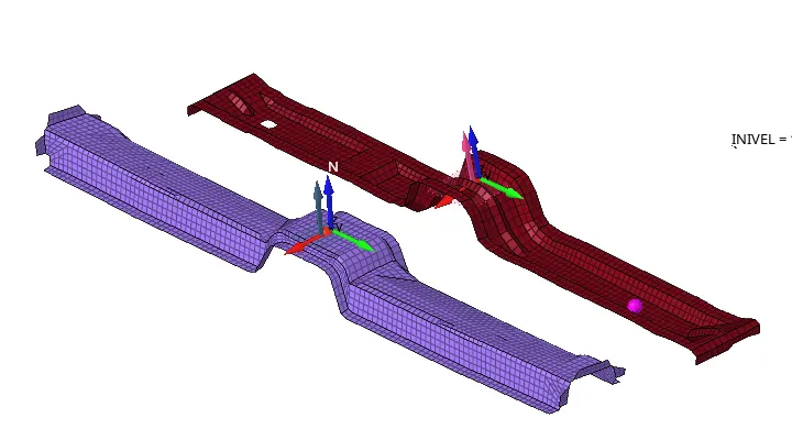
- FOR the sectional forces, firstly we have to define the crossection at the cross members
- members that are connected to the both sides of the chassis are to be used
- for these frams amd sects are rquired so we have to create the frames and the correspondinf sect
- SLOVER>--FRAME>--MOV>-- select the x, x-axias, xy plane nodes
simillarly create the sects with N1,N2,N3 an d them call the shell fuction that is defined as a SET
2.Intrusion at B pillar,hinge pillar and fuel tank region.Provide recommendation on what can help to reduce Fuel tank intrusion:
- Intrusion are noting but the amount of disatnce that a node mode nirmal to the direction of force
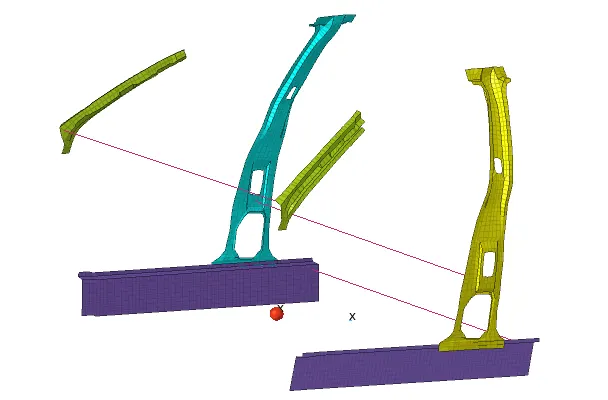
- this can be done in two methos, direct node method and sprinf element method we, follow the later method
firstly we have to create a 1D spring element and assign a property to the spring
- this 1d elements are to are to be created at the nodes in B-PILLAR, HINGE PILLAR, FUEL TANK components
- here entity type has to be ELEMENTS , as these springs are 1d elements by nature
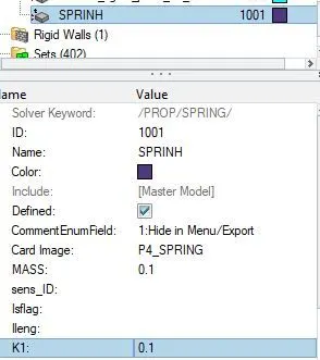
- give the stifnessas minium as possible and spring mass as 0.1
- create seperate out put blocks for these intrusions, don't forget to define the slement as SPRING_P4
Peak velocity of inner node of the door.:
-
VELOCITY at the inner most node of the door is to be needed
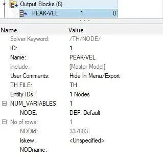
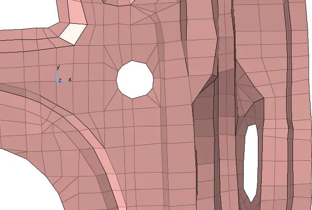
- a skew has to be created because , for the measure ment of diaplacement a moving frame has to be defined
- > SLOVER>--TH>--NODE> CREATE
- select the corresponfing node where a skews is created above
RESULTS:
Lets discuss results one by one,
- displacement and von misses stress conturs are shown in the figure
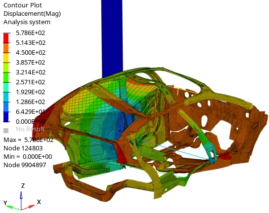
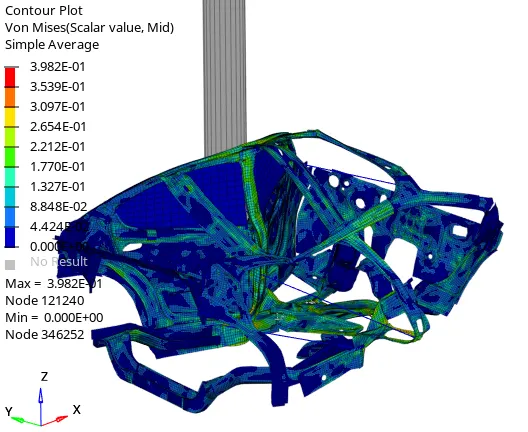
- here, from the conturs we can say that the maxium stress occur at the B-PILLAR , and also it acts as a piot for the total crash.
- from the second figure we say that there are only a few areas where the stress are being imported mostly near the B-PILLAR region
- the maxium stress that is present in the model is as given 3.98e+1N/mm2
- the maxium displacement is as shown 5.786e+2mm at the node 9904897
- so, there will be certaion mount bodies provided at the bottom frame of B-PILLAR , which takes most of the impact reducing the imoact on the occupant
1.Sectional force in the cross member:
- from the crossections created on the cross members we have derived results and plotted graphs from those
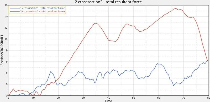
- from the above figure , the total resultant force for crossection1 is 6KN,this member near to the front axial it does recieve much of the force transmission , as it is away from the piotal-B-PILLAR component
- where as here the cross member selected is in connection to the B-PILLAR component, so it recieves a moxium force of 15,56KN
2.Intrusion at B pillar,hinge pillar and fuel tank region.Provide recommendation on what can help to reduce Fuel tank intrusion:
- intrusion are to check at B pillar,hinge pillar and fuel tank
- these intrusion are nothig but amount of displacement a node move while crashing, here we have create a spring element in assocation with the intended nodes
- these displacements are, measurred by how much the spring is eongated along the direction of force
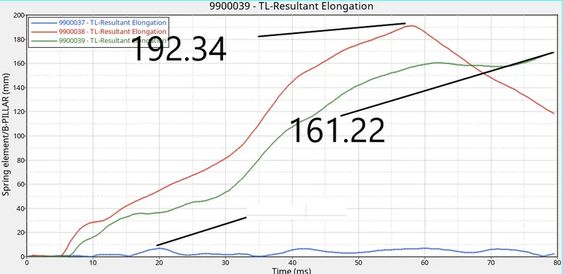
- from the graph it is clear that the maxium intrusion ia at the FUEL TANK, it means that the elongation of the spring is minium at the region'
- the maxium elongation is at the B-PILLAR , as it recieves the maxium force as a result the spring element compress more
- this can be avoided by increasing the strength og tthe component , or by changing the material
3.Peak velocity of inner node of the door.
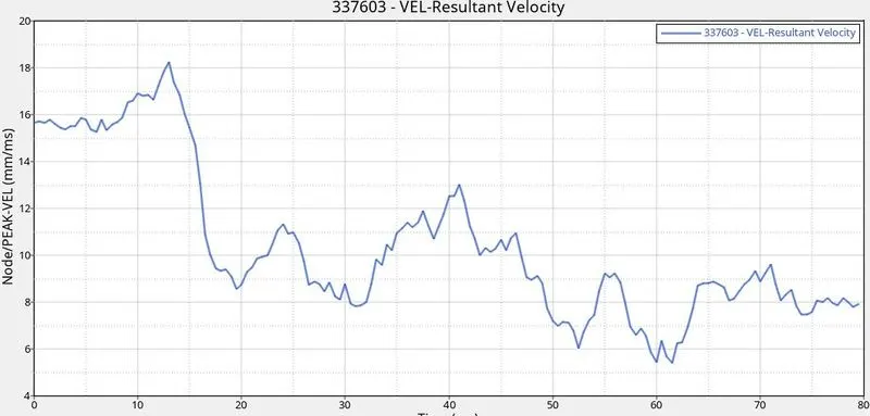
- a skew is created in order to measur the maxium velocity at the inner side of the door pannel
- as, we have created the pole in contact to the model, so the impact at the very beguning with a velocity of 15.65mm/ms
- after the impact the velocity decreases, and we can aso observe the , fluations in the velocity change , this is due to the deformation at the time of peak crashing
4. energy intendations:
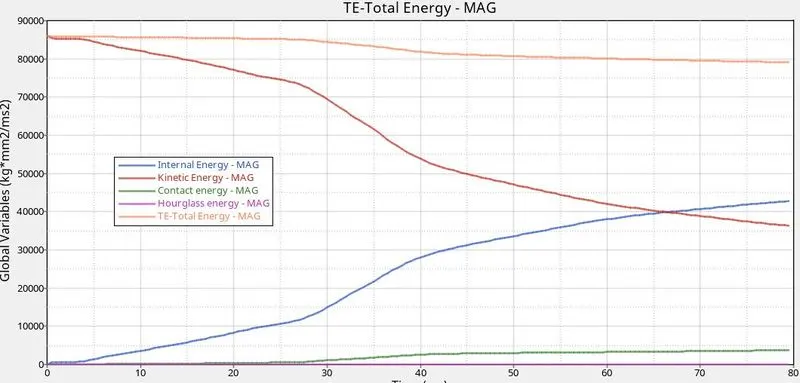
- here, internal energy and kinectic energy behave exact opposite to each other, this indicate that as the KE decreases IE increases due to the force recieved from the pole , which interm convert to the energy
- as we have used reduced integration scheme, hour glass effect is zero
- contact energy is the type of energy create, where one node comes in contact with the other , the resistance force oppose any such movement, here contacy energy arause ath the time of 4ms after that it keeps on increasing
CONCLUSION:
- We can totally see the maxium stress, displacement, intrusions are maxium at the pivotal pole region,so we can provide extra rods at the inner door panel or even change the material of the component