Side Impact Analysis using Hypermesh and RADIOSS
Problem Statement -
For the given reduced model of the front impact structure of a 4W automobile perform frontal crash analysis using hypermesh to setup the load case and RADIOSS as the solver.
Theory -
Any crash scenario involves huge changes in an object's inertia and leads to high dissipation of energy. This energy has to be absorbed by the car's structure before it reaches the passenger. This absorption of energy can only occur when the material deforms. Hence, the crash structure is designed in a way to crumple opposite to the direction of impact force and the remaining force is directed to the rest of the structure systematically.
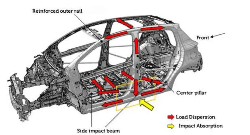
The major load-carrying members in case of a side impact are the B-pillar, side-impact beams, floor cross beams, and the outer roof rail. The main aim of this analysis is to check for intrusions into the passenger cabin as well as the fuel tank region.
The model given to us is restricted by the 100,000 nodes limit set by the hypermesh student edition. Mass of various parts such as the engine and drivetrain is added using the 'Add mass' feature. This ensures that although the model is reduced, it's center of gravity lies in the correct place, and the inertia of such heavy components is taken into account.
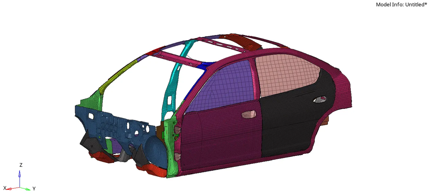
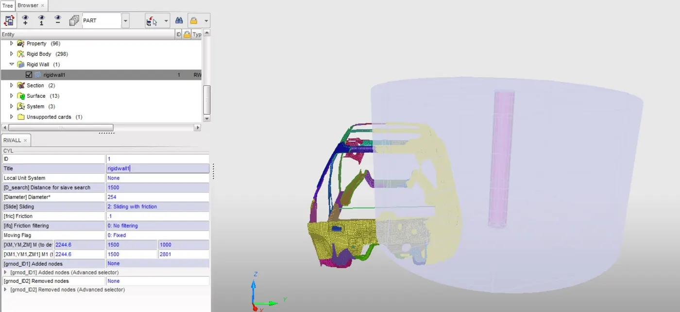
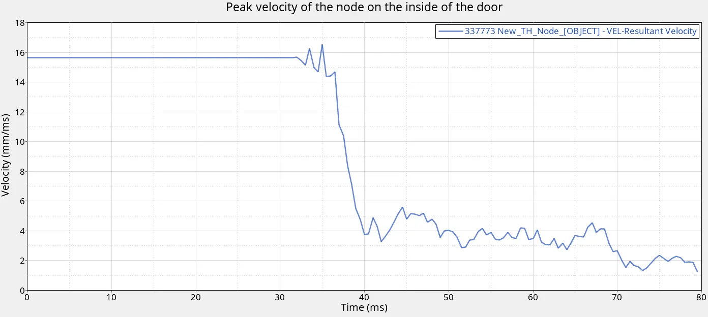
As per the test procedure, the vehicle only has a lateral initial velocity of 35mph and it is crashed into a rigid pole of diameter 254mm or 10inches. The main observations will be the sectional forces in the cross beam, intrusions at the B-pillar, hinge pillar, and fuel tank region, and peak velocity of a node on the inside of the door.
Procedure -
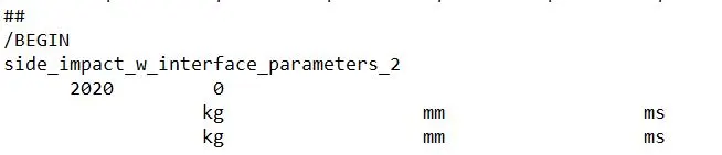
1.) Check unit system - This helps to avoid mistakes while inputting parameters to define the load case. Can be checked in the 'example_0000.rad' starter file.
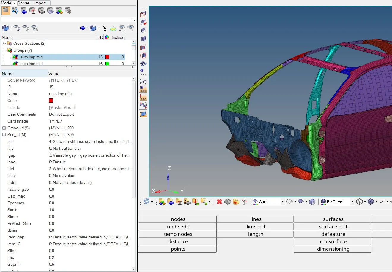
2.) Create interfaces with recommended parameters - Interfaces are defined to model how parts interact when they come into contact with each other or themselves. For shell elements that have a thickness assigned, a gap/space is assumed between the master and the slave nodes. Spring elements with linear/non-linear stiffness are created between the slave nodes and their projections on the master elements. This is called the interface penalty method. The linearity of these assumed springs depends on the type of interface chosen. The type of interface depends on the nature of contact between the said parts.
- Type 7 (variable stiffness) node to surface contact
- Type 11 (variable stiffness) edge to edge contact
- Type 19 (variable stiffness) Type 7 + 11
- Type 24 (linear stiffness) node to surface and surface to surface contact
Important interface parameters that describe the nature of interface -
- Igap - Determines how the size of the gap is calculated.
- Gapmin - Minimum gap for activation of the interface.
- Inacti - Action to take if initial penetrations exist.
- Istf - Affects how the stiffness of the interface is calculated.
- Iform - Friction formulation.
- Stmin - Minimum stiffness to be used in the interface.
- Idel - Deines what to do with the slave nodes and the master segments if the elements that they are attached to fails.
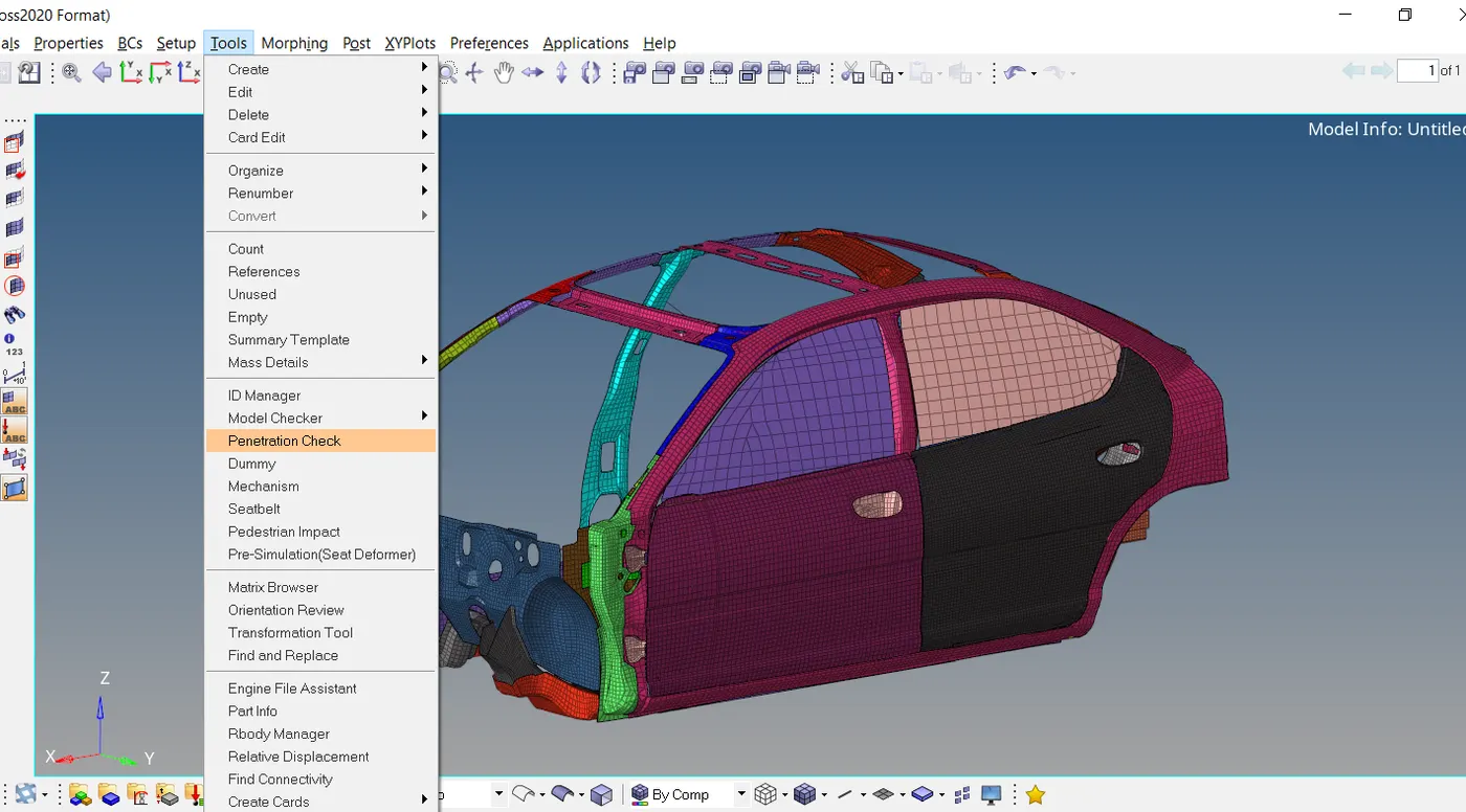
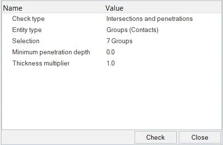
3.) Check for penetrations and intersections - Penetrations result if, in an interface, the slave node is closer to the master segment than the calculated gap. An error occurs in this case and the parameter - 'Inacti' offers options to remove any such penetrations. But before using any such automated methods, a penetration check and removal can be done manually.
4.) Create a rigid wall - A rigid wall does not physically exist but it is a kinematic condition imposed on the slave nodes. Rigid walls allow for an easy way to define an interface between a rigid surface and nodes of a deformable body. The rigid wall can be defined as - an infinite plane, a sphere, an infinite cylinder, or a parallelogram. The wall can be fixed or can have an initial velocity with respect to a local frame of reference. In this case, we'll be creating a cylindrical rigid wall of diameter 254mm.
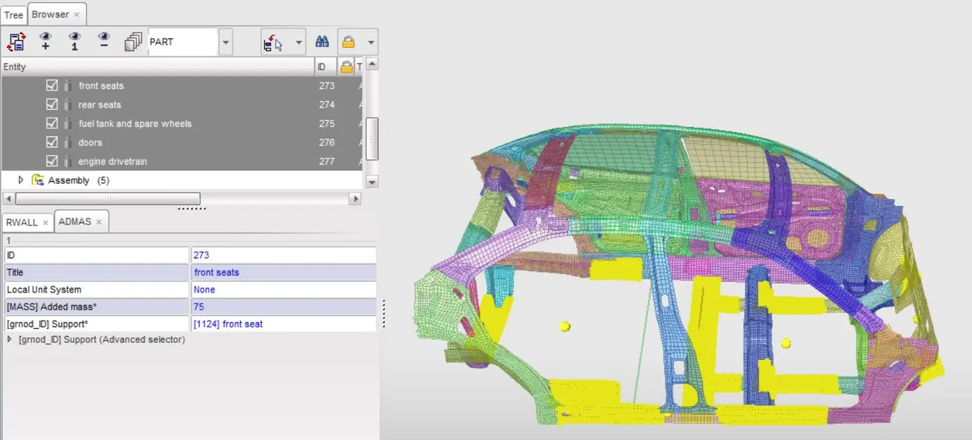
5.) Add mass wherever necessary to achieve the target weight and center of gravity similar to a full car model -
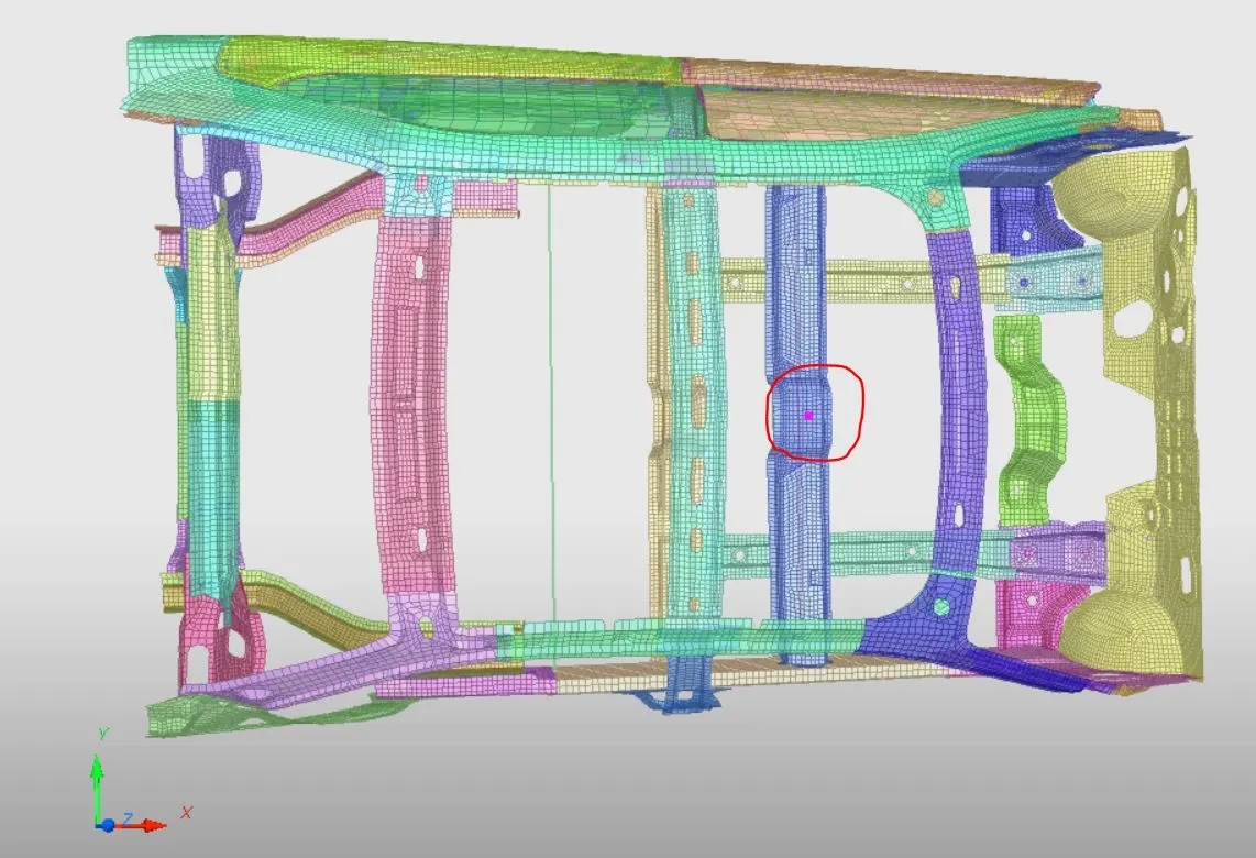
For parts that don't contribute to the structure's stiffness but have a considerable mass that would affect the inertia and center of gravity of the car, masses can be added near their points of attachments. This can be done by creating groups of nodes or shells that demarcate the position of the part. Mass can either be added to each node/shell or can be distributed to each node/shell. This process has to be done for various parts of our car such as the engine & transmission, the fuel tank, rear seats, spare wheel, and doors.
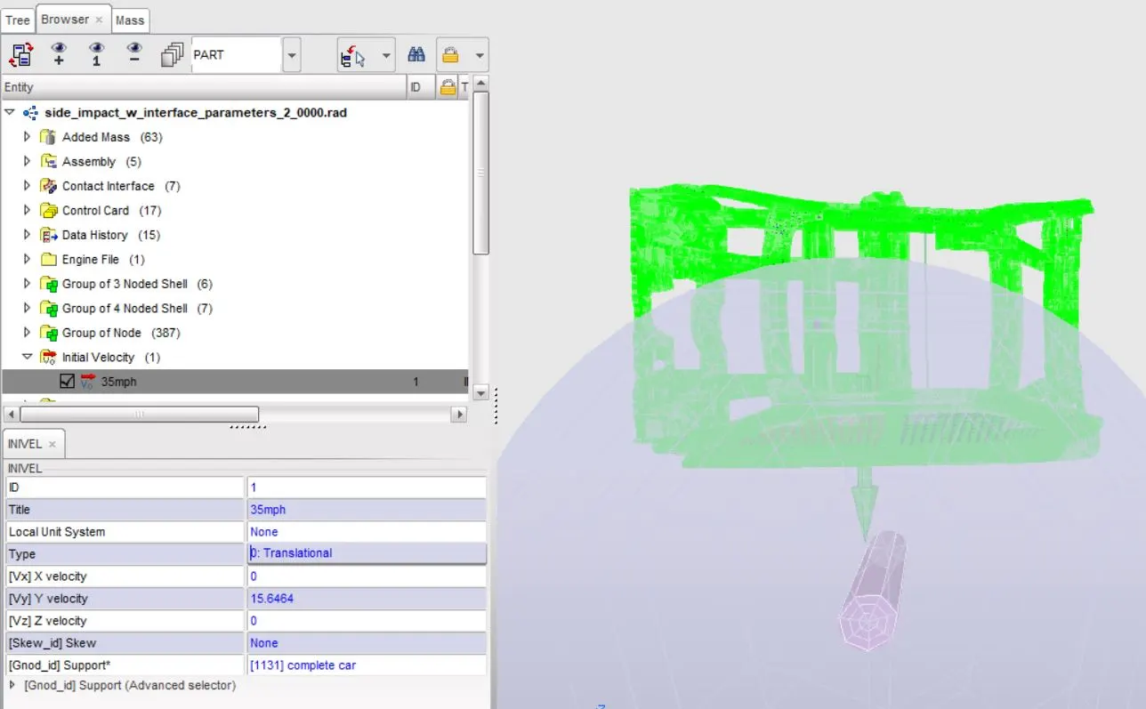
6.) Give an initial velocity to the vehicle - '/INIVEL ' define an initial velocity on a group of nodes. It does not require a function and does not vary with time. As required by the analysis, we provide an initial velocity of 35 mph or 15.6464 mm/ms to the vehicle in the lateral direction or Y-axis in this case.
7.) Create output requests for analysis of the crash -
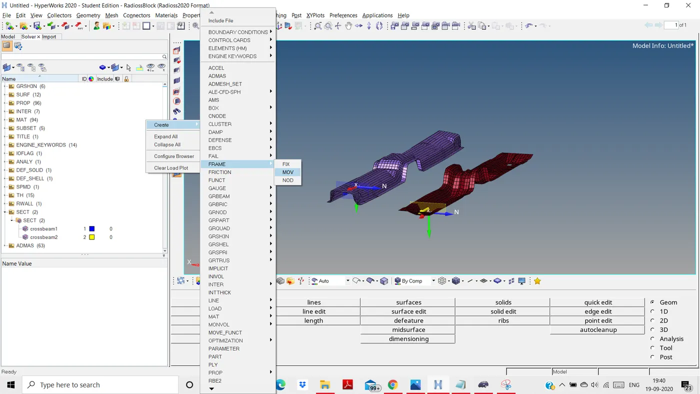
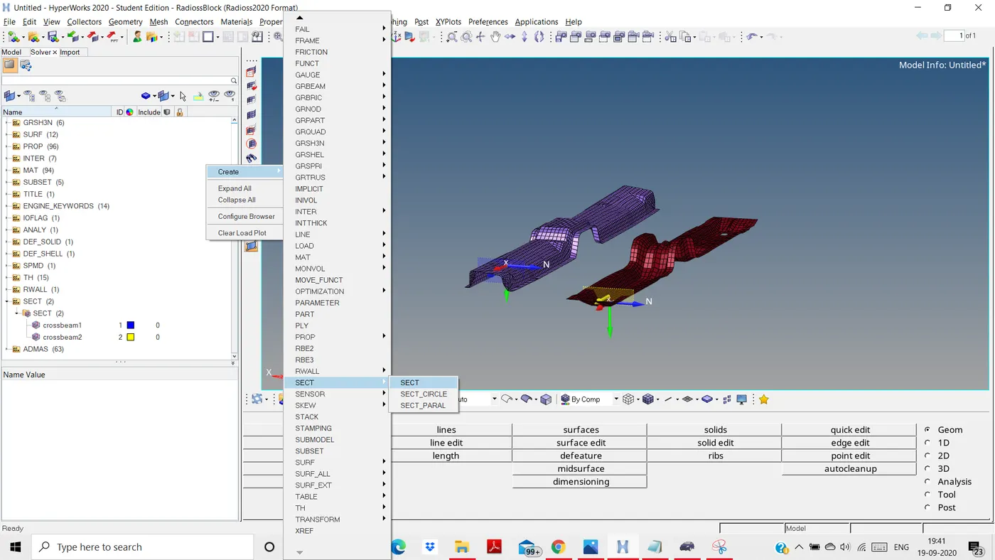
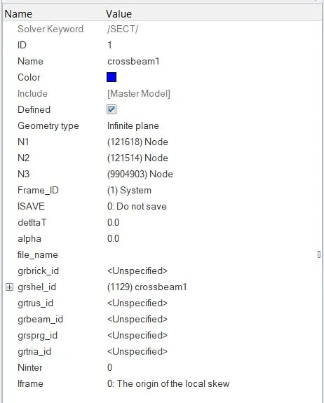
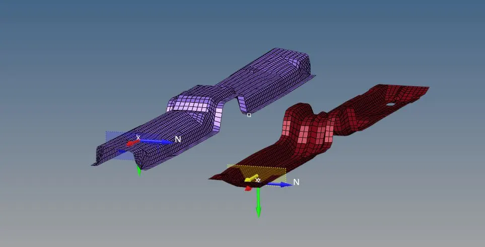
a.) Sectional forces - To validate the flow of force from the B-pillar to the floor cross beams we create cross-sections of elements along this complete path and derive the normal forces acting on each section. Cross-section definition requires a local frame of reference and input of three nodes to further define the local skew. Also, a group of shells around the cross-section have to be input. This section can then be used as an input to a /TH (time history) output block which by default gives outputs of normal & tangential forces among many others. Similarily we create cross-sections at the cross beams.
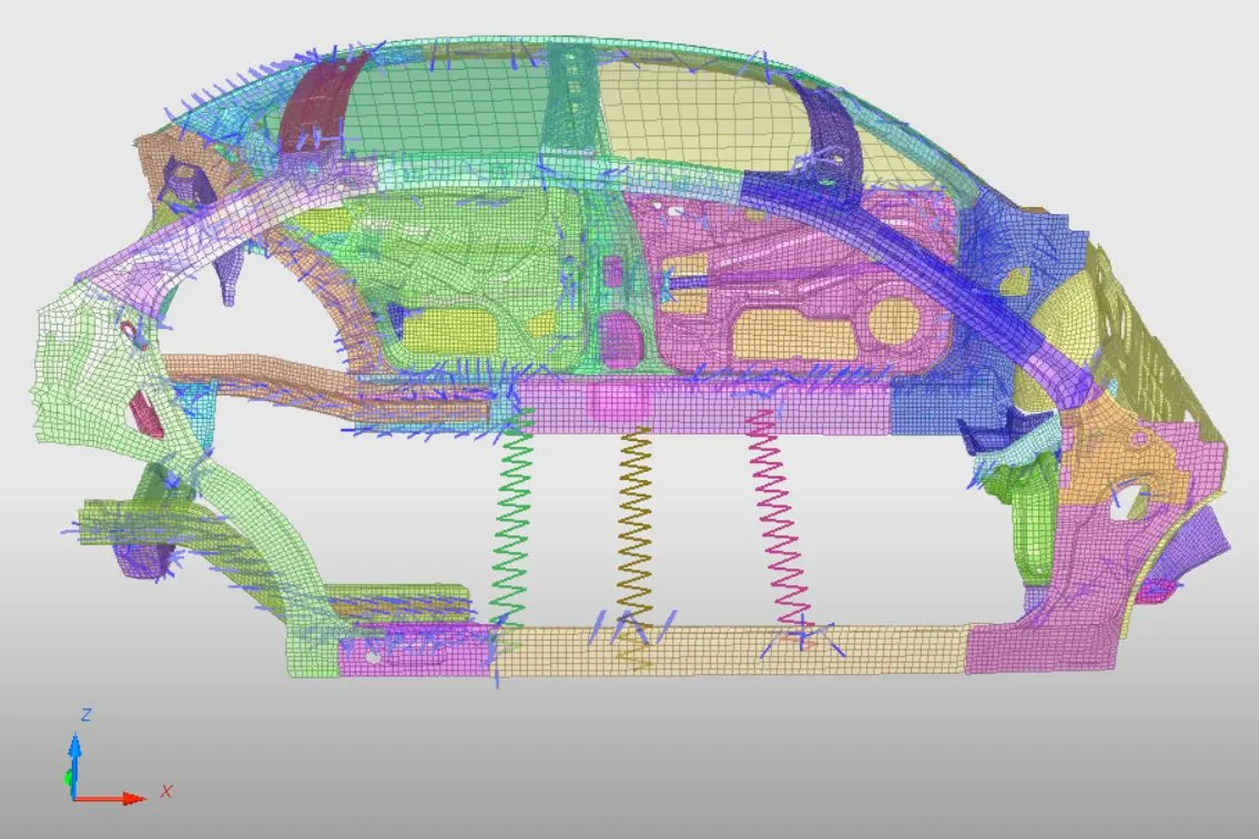
b.) The intrusion at the B-pillar, hinge pillar, and fuel tank region - To validate this for our load case, we pick two nodes on the dash wall separated by some distance and connect them to the first crossbeam using a 1D 2 node spring element. The spring is assigned a very small mass and stiffness. The deformation of this spring with respect to its fixed point at the cross beam gives us the required output of intrusion. A /Th output block is assigned to obtain the deformations along Global Y-axis among other outputs.
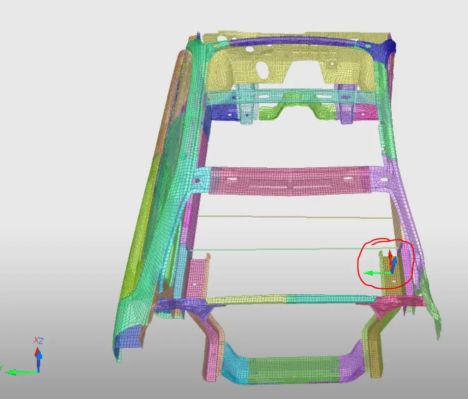
c.) Peak velocity of the node on the inside of the door - To receive this output firstly, we create a local fix skew at a location that has no motion relative to the rest of the vehicle. With respect to and input of this skew system we create a nodal /TH output block to receive the output of velocity among many other outputs.
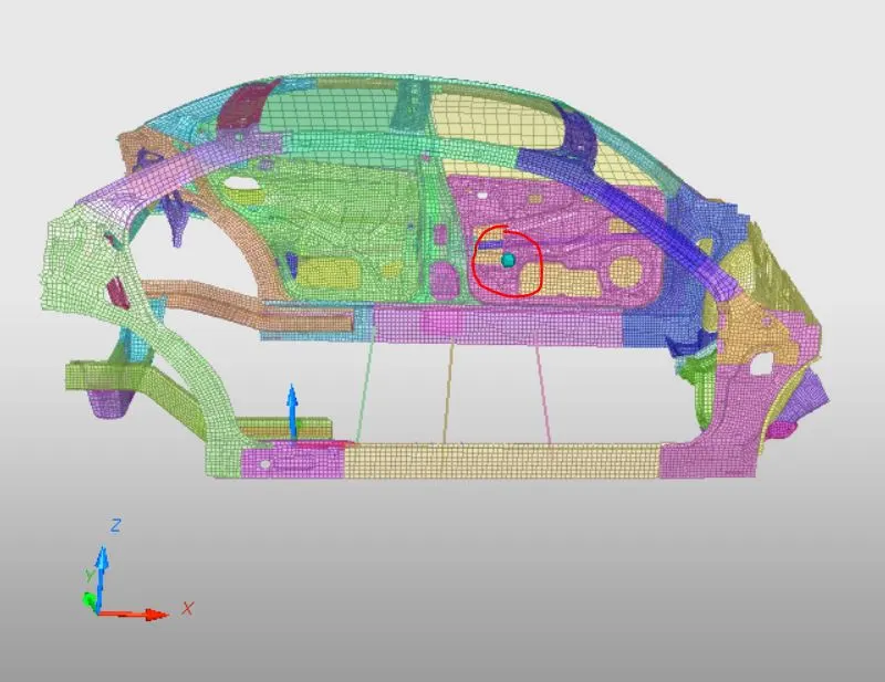
8.) Set stop time and time step - Set total simulation time to 80ms and the minimum elemental time step to 0.5 microsecond or nodal time step to 0.1 microsecond.
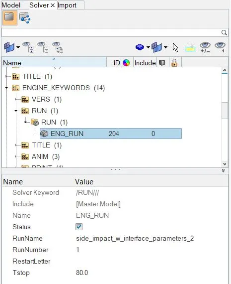
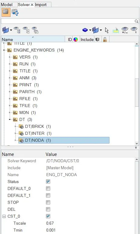
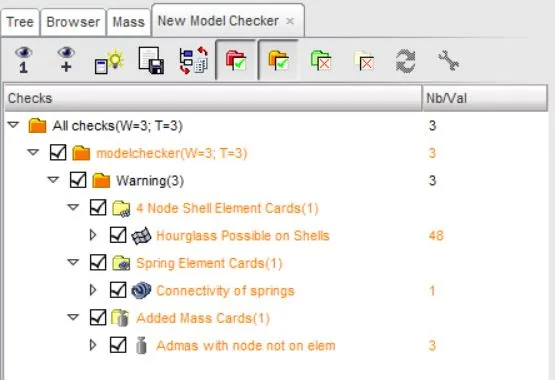
9.) Run the model checker - It checks for any and all potential issues that could terminate the solver when run. Issues such as incompatible kinematic conditions, under-defined or wrongly defined parameters, etc. can be corrected before running the simulation. We have no major errors after load case set up and only some insignificant warnings such as the presence of some free nodes that we created for reference. Such warnings can be ignored or dealt with using autocorrect tools.
Outputs and observations -
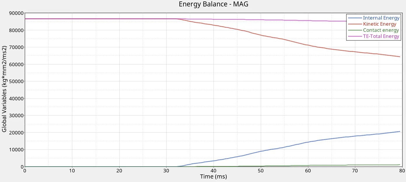
1.) Energy balance -
Total energy = Kinetic energy + Internal Energy - Contact Energy
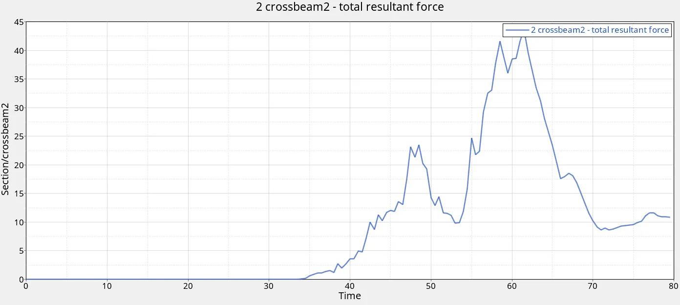
2.) Cross-sectional forces - Since the pole is aligned to the B-pillar of the vehicle which is in line with the crossbeam -2 , the maximum total resultant force of 43kN can be observed here. Crossbeam-1 ses a peak of 8.5kN force. 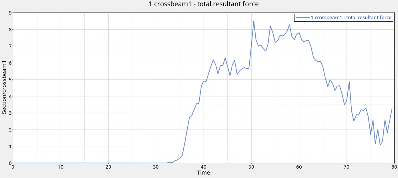
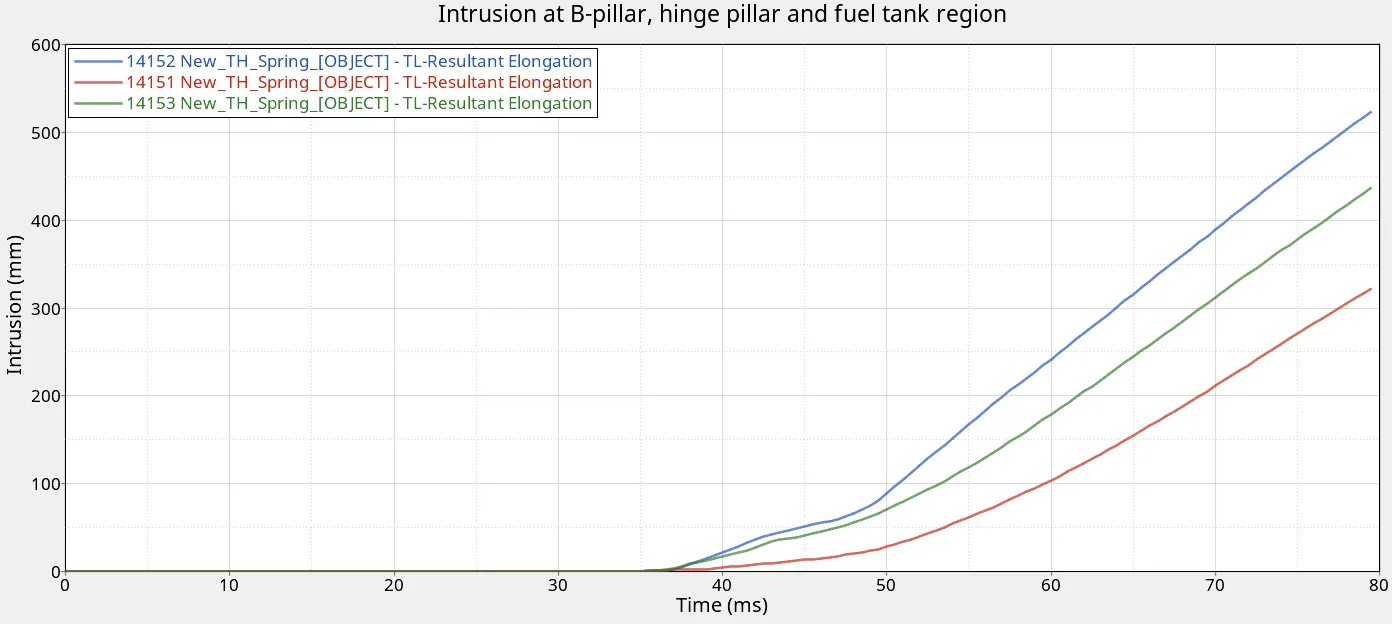
3.) The intrusion at the B-pillar, hinge pillar, and fuel tank region - The penetrations in all three cases are in excess of 200mm. Maximum penetration of about 525mm is seen at the B-pillar. The chassis clearly needs more stiffness in this lateral direction to be deemed safer.
4.) Peak velocity of the node on the inside of the door - Maximum value recorded is just over 16mm/ms.
 +
+
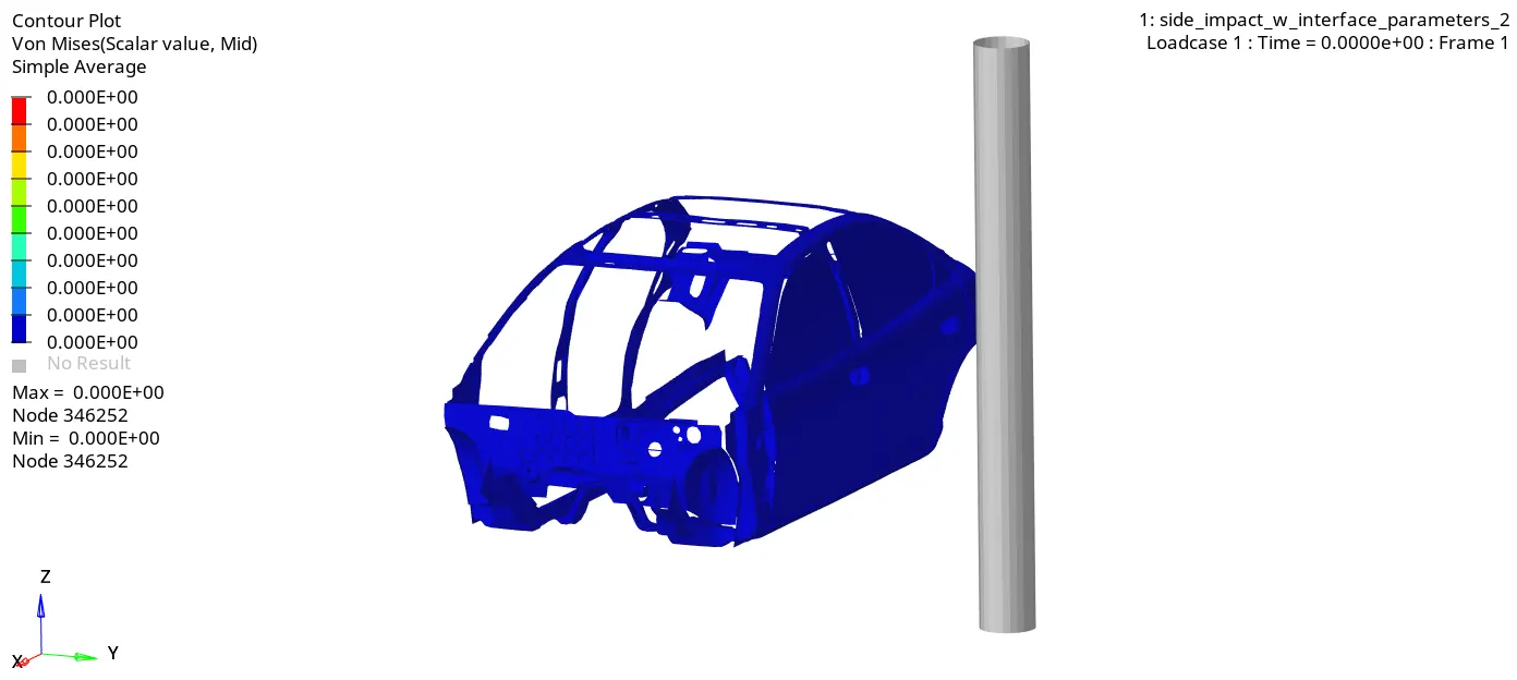
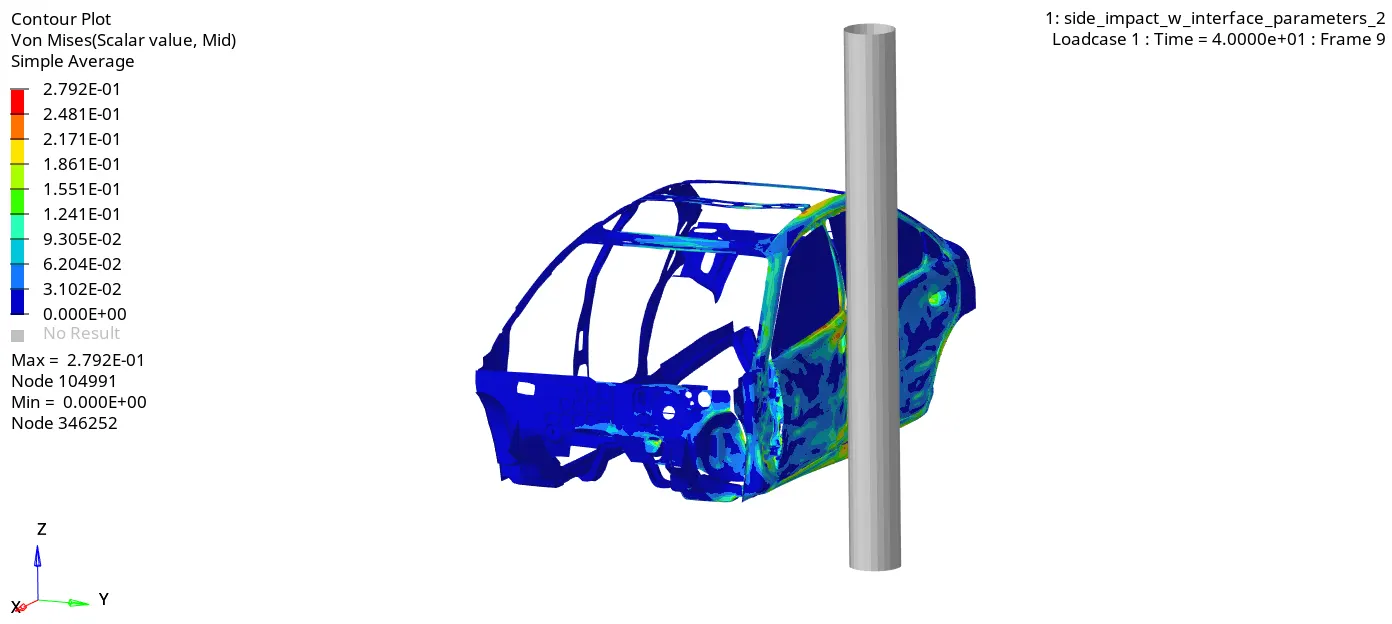
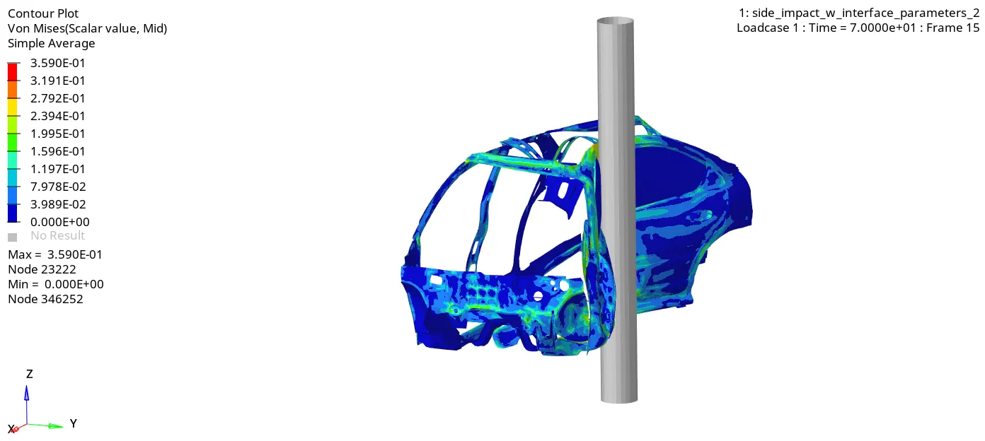
5.) Stress Contours -
Learning Outcomes
- Creating interfaces
- Checking intersections and penetrations
- Creating rigid walls
- Mass balancing
- Applying loading conditions
- Obtaining potential warnings and errors using the model checker
- Creating cross-sections and output requests.
Conclusion
The simulation shows to prove that a reduced model can provide close to accurate results which could save computation time and thus cost before design finalization. Here, all members in the lateral direction are responsible for stiffness and deformation. Improvements to reduce penetrations can be made keeping this in mind.
Google drive link -
https://drive.google.com/drive/folders/1KPywaiWpZjSy0q-VuoG9vwA1uaballtb?usp=sharing