Side Pole Impact Test – BIW
Side Pole Impact Test – BIW
Objective:
The objective of this project is to simulate side pole impact of a car’s BIW model, obtain the requested forces, displacements and velocities experienced by the model to study the safety of the BIW frame during a side impact with any obstacle like a tree, pole, Fitch barrel, etc.
Case Setup and Model Setup:
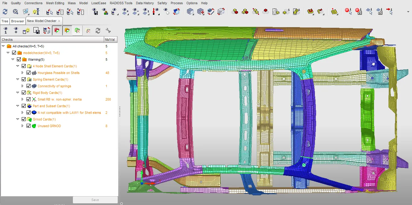
1. The model checker is run in hypercrash immediately after importing and the errors and warnings are then checked to find any unassigned properties or materials for the components.
2. The errors in the given model are depicted in the picture below
3. The spring element with connectivity warning is checked and the correct connectivity is established or the element is deleted and a new spring element is created in the same place.
4. Since there are no unassigned materials or properties, the thickness intersection is checked and if any intersections are present, they are removed by manipulating the nodes
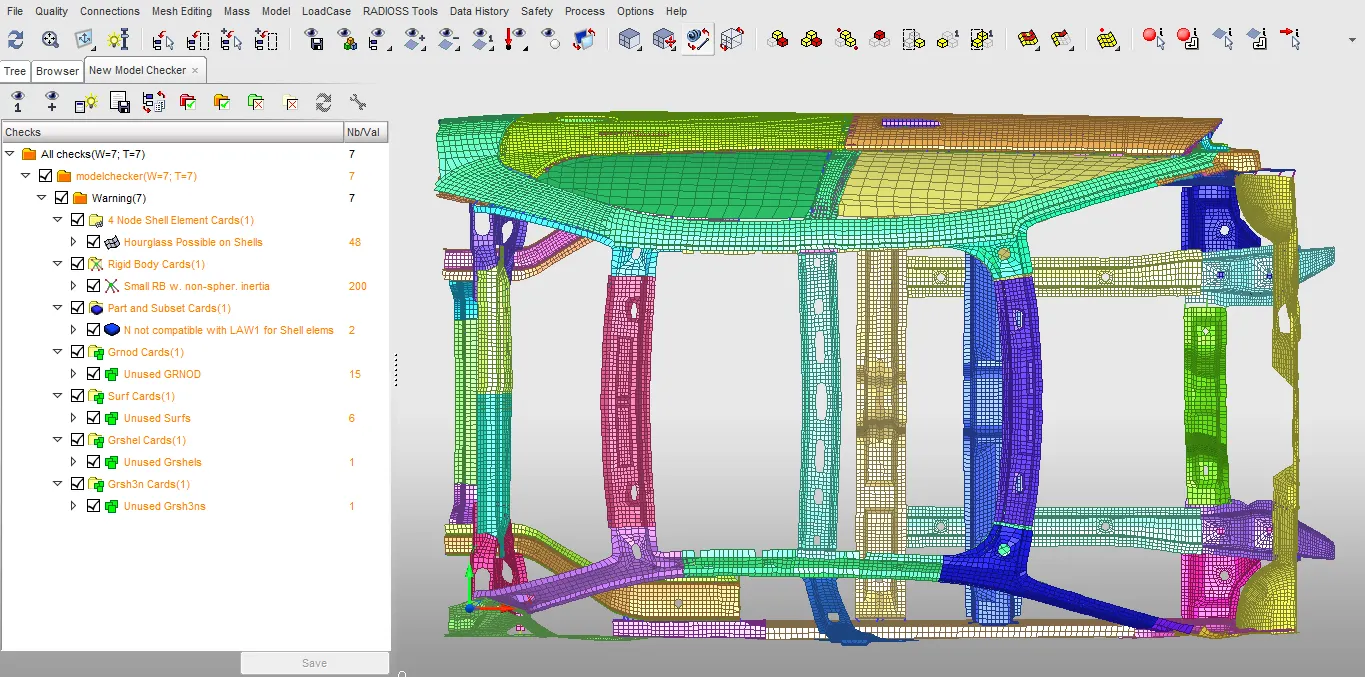
5. Then, the connectivity of all the parts in the load path is checked to make sure that there are no free parts as it might lead to incorrect results.
6. Since there are some free parts, they are connected using springs.
7. After these preliminary operations are done, the load case is set up.
Setting up Load case: The unit system followed is kN, kg, mm, ms.
- Rigid Wall/ Pole
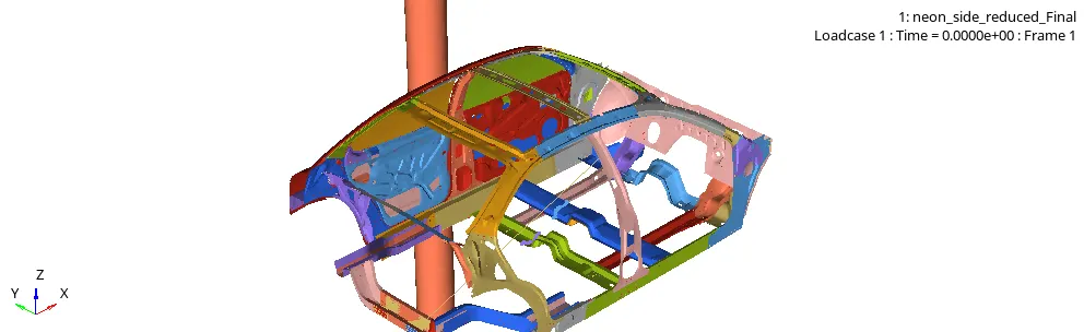
1. A cylindrical rigid pole of diameter 254 mm is created right next to the B - Pillar of the car by choosing two coordinates that represent the axis of the pole
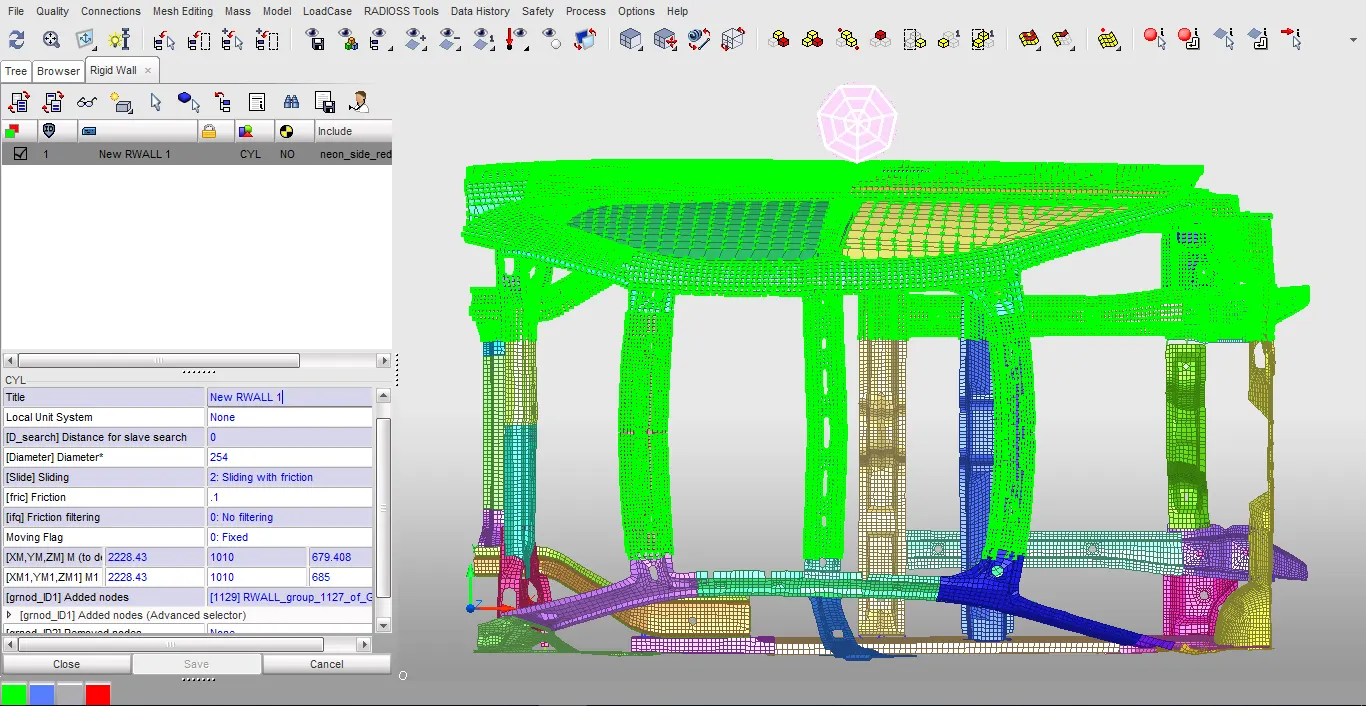
2. A set of nodes that are on the driver side of the car are selected as slave nodes.
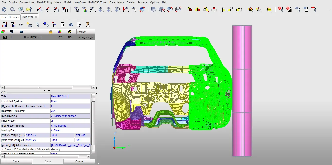
3. Care should be taken not to have too many slave nodes for rigid pole as it increases the computational load.
2. Gravity (GRAV)
1. Gravity is applied to all the nodes in the model
2. To apply gravity, a function/graph is first defined.
3. In this model, as the gravity is acting in -Z direction, the direction in translation option is set to Z.
4. To make sure that the gravity is acting in the -Z direction, either the Y- Scale factor is set to -1 or while defining the graph, Y value is entered as -0.00981.
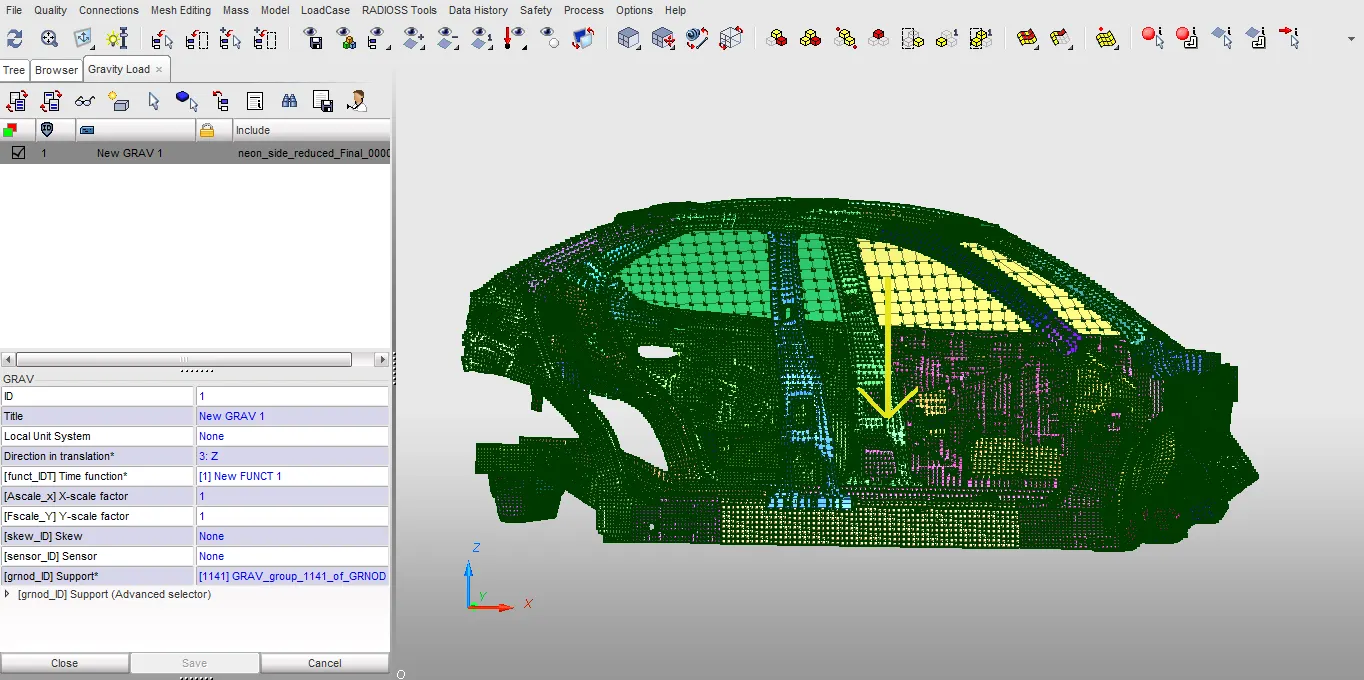
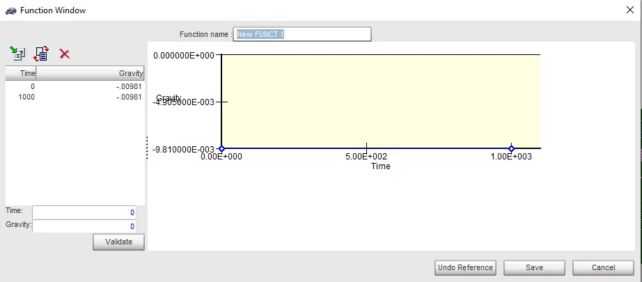
5. A yellow arrow in the model indicates the direction of the gravitational load.
3.Initial Velocity (INIVEL)
1. Initial velocity is also applied to all the nodes.
2. The initial velocity is 15.64 mm/ms towards the cylindrical pole i.e. in the +Y direction
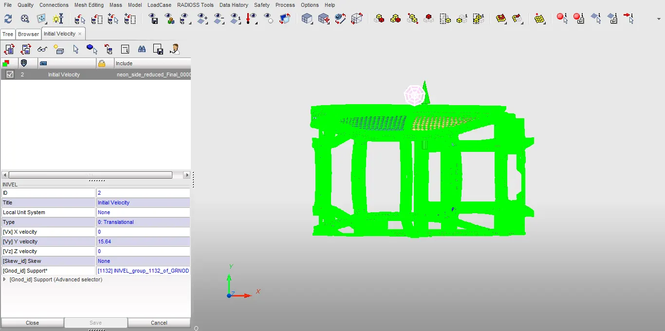
3. The green arrow in the model depicts the direction of initial velocity.
Setting up interface:
Global Interfaces:
1. A global contact interface is used here to take into account self-contact or penetration of the BIW parts during impact with the rigid pole.
2. Hence a multi-purpose contact (TYPE7) is defined in the model.
3. In the contact interface tab, a new contact interface is created, by selecting surface of all parts as master surface and selecting all the nodes in parts as slaves.
4. This establishes a self-impact interface which takes into account the penetration of components in the model.
5. The optimum parameters for type 7 are then set.
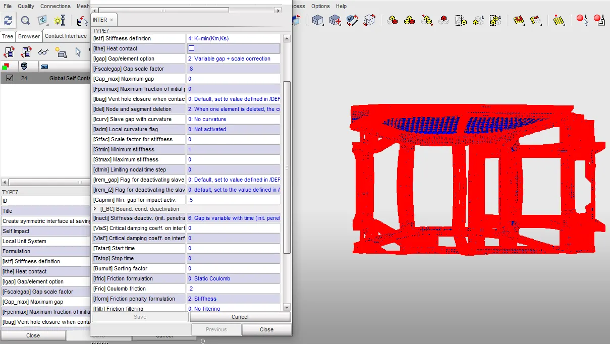
Setting up Cross sections:
Cross sections of cross members:
1. Cross sections are used to obtain the physical quantities like normal force, moments, work of forces and moments, etc. in certain area/region/cross section within a component.
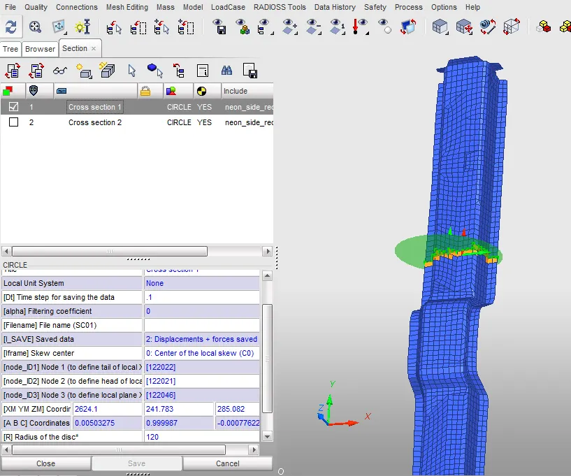
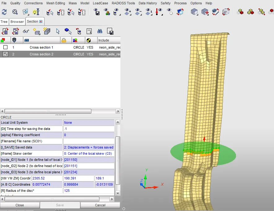
2. To create a cross section, in the time history, select cross section (Circular)
3. Select 1st node to define the tail of local x axis, 2nd node to define the head of local axis, 3rd node to define the local xy plane, pick a node for the origin of the circular cross section and select N1-N2 option to choose the cross section plane normal.
4. The diameter of the circular plane in cross section 1 is 120 mm
5. The diameter of the circular plane in cross section 2 is 125 mm
6. Then select the required elements for which the cross sectional forces are required
Mass Balance (ADMAS)
1. As only the side portion of the BIW frame involved in absorption of most impact force is used here in this project to reduce computational cost, additional mass must be added to the frame to simulate or imitate a full car model with a balanced center of gravity.
2. The reduced frame used in the model weighs approximately 166.3 Kgs. Hence mass is added strategically to make sure that the final weight is 700 Kgs and the center of gravity lies right next to the driver
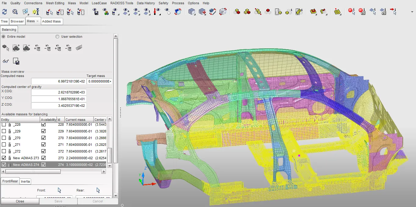
3. The ADMAS type used in this model is type 1.
4. When type 1 is used, the user defined mass is distributed within a group of selected nodes.
Output requests:
Data History:
1. Data history is used to record some very important physical quantities like force, displacement etc. The physical quantities are recorded along with the simulation time and save in T01 file.
2. This file can be used in hypergraph to generate different plots to better understand the simulation.
3. Radioss usually saves the global variables like Internal energy, Kinetic energy, hourglass energy, contact energy, etc by default.
4. Other quantities like forces can only be saved if data history is requested for the specific type of force or moment or work.
5. For this project, the data history contains cross sectional forces, velocity of node and displacements.
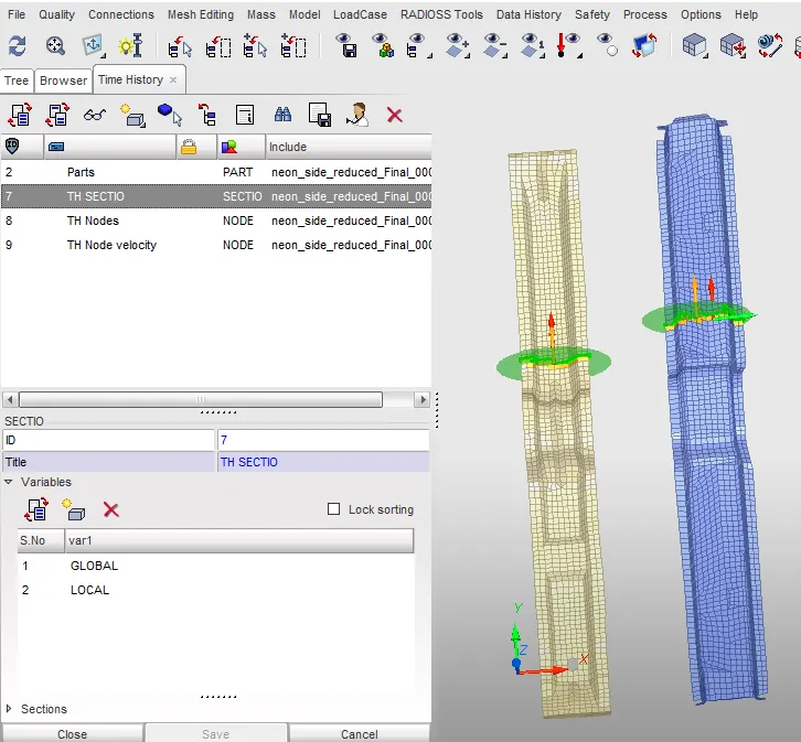
6. Whenever a cross section is created, it is automatically added to data history. All that has to be done is to choose the required physical quantities to be recorded.
7. For cross sections, the local forces and global forces are chosen as output variables
8. For intrusions/ displacements, usually the relative displacement is recorded
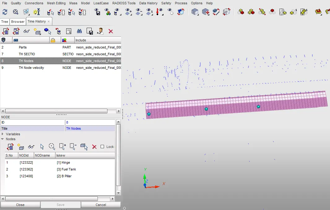
9. Hence to establish a local frame of reference to measure the relative displacement, a moving frame is created on the rocker opposite the nodes for which the intrusion is to be measured
10. Go to Time history, add new TH of Nodes, choose the nodes to be monitored, select the newly created moving frame as frame of reference, and select the physical quantities to be recorded which in this case is displacement and velocity
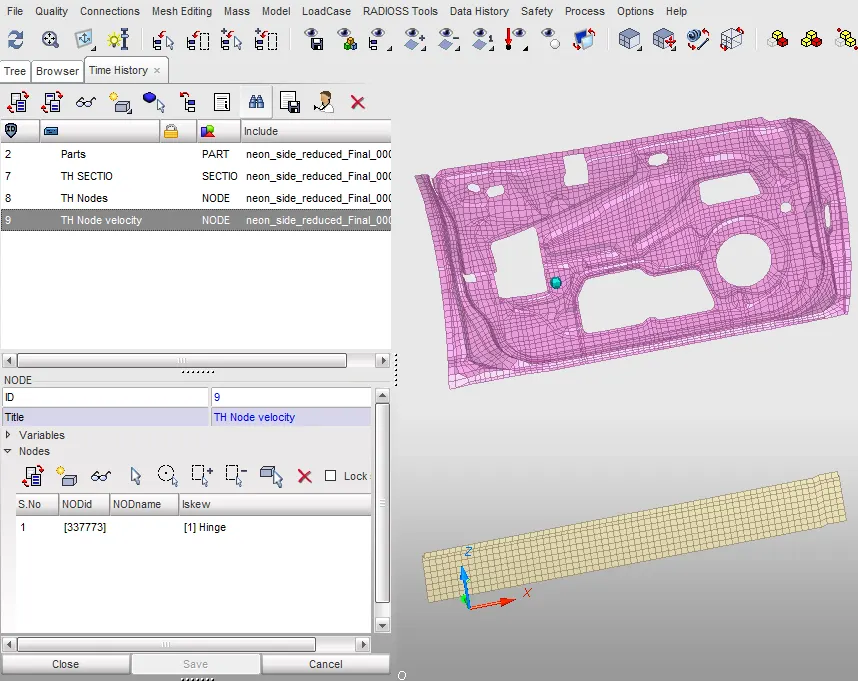
11. Here, the output variable is set to default which saves the default physical quantities.
Animations:
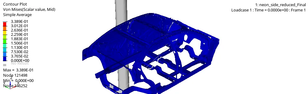
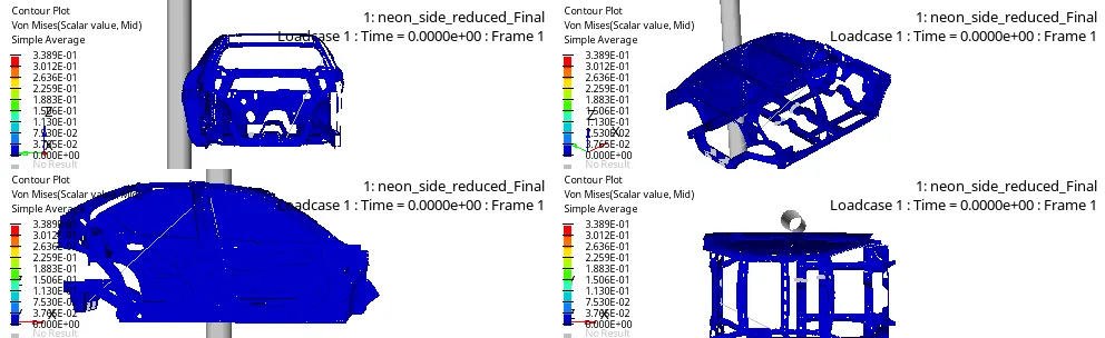
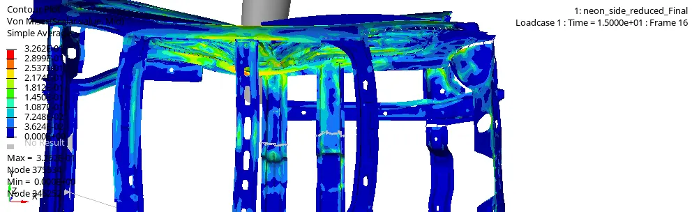
1. Animations are also created to visually assess the deformation, mass addition, stress, strain, etc
2. To request animation, in the control cards tab, under engine keywords, toggle ANIM_DT and set the time interval to 1ms.
3. Next, the required animations like element stress, strain for shell elements, brick elements, displacement, velocity etc are requested in the same way.
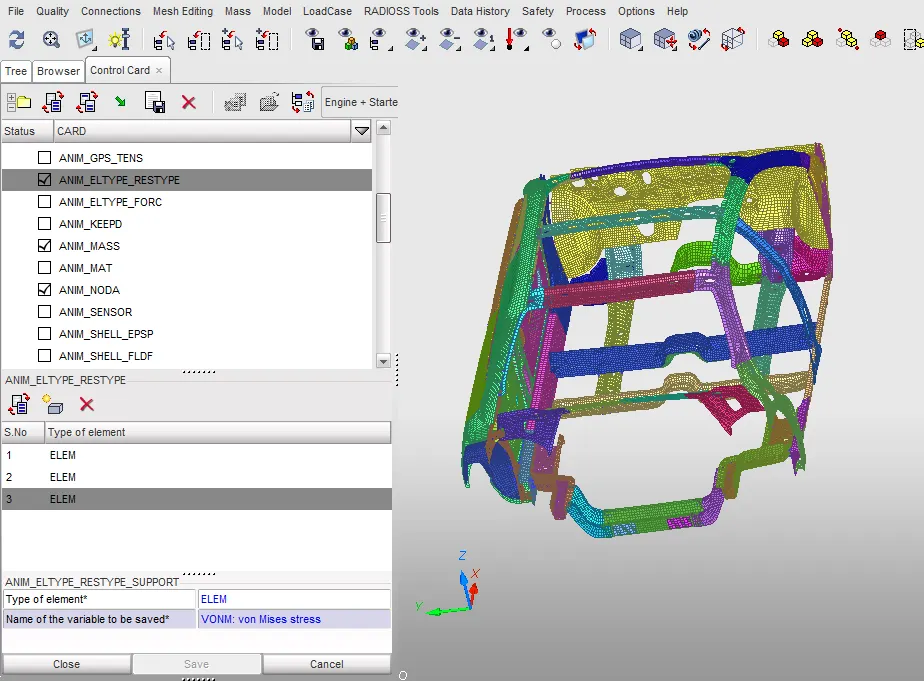
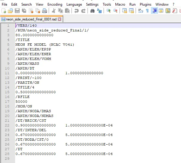
4. Another method to request animation is to edit the _0001.rad after the model is exported.
5. As the software mainly uses keyword, the keywords for animation i.e. /ANIM, /ANIM/SHELL, etc. can be used to request different types of animations for different element types
Observations/Findings:
Animations:
Energy Balance
1. After the simulation is done, energy balance is checked by plotting internal energy, contact energy, hourglass energy, kinetic energy in a graph.
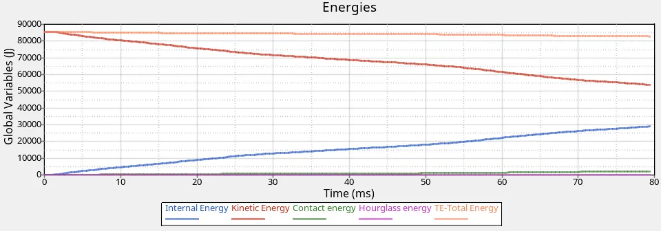
2. The total energy is more or less constant without any abrupt change.
3. The kinetic energy is maximum and gradually decreases.
4. The internal energy is zero at the start of the simulation and gradually increases.
5. The engine output file is also checked to make sure that the energy error and mass error are within acceptable limits
6. The energy error is -2.5 % which is within the acceptable limit of less than 15 % and mass error is 0.0034 % which is within the acceptable limit of less than 2%
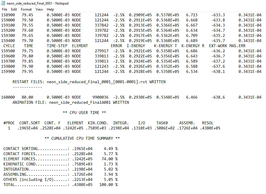
7. The contact energy is 2.4 % of the total energy, (hourglass energy + Contact energy)/ Total energy = 2.5 % which indicates the simulation results are valid and acceptable.
Sectional forces in the cross members:
1. The sections are used to find the magnitude of the physical quantities within a particular section of a part or a component.
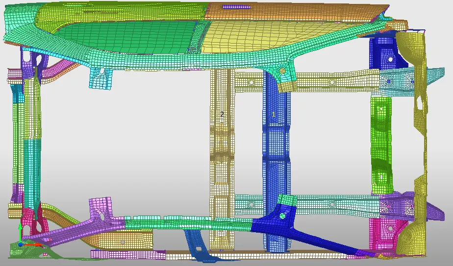
Cross member 1 - Blue Color
Cross member 2 - Golden Color
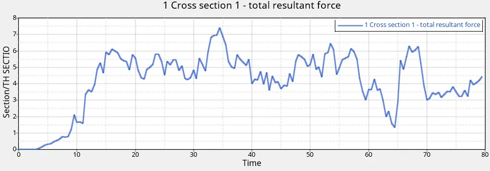
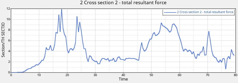
2. From the graphs, it can be concluded that the sectional forces (Total resultant forces) in cross member 1 and cross member 2 are are 7.39 kN and 11.915 kN respectively.
3. As the cross member 2 is in the close proximity to the pole, it absorbs most of the energy while the cross member 1 absorbs lesser energy
Intrusions on the B pillar, Hinge pillar and fuel tank region.
1. The testing is carried out in such a way that the impact happens on the driver’s side.
2. Hence, it is vital to examine how much the damage will be to the driver due to the intrusion of parts during the impact with the pole.
3. The maximum intrusion occurs along the line of impact with the pole.
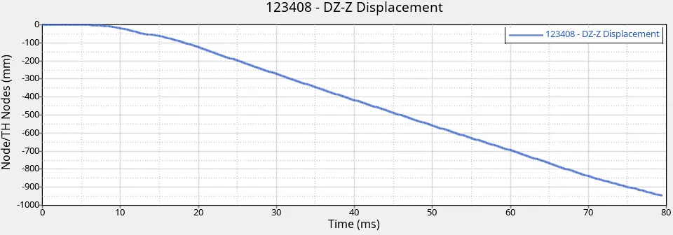
4. The magnitude of intrusion at B Pillar is 946.52 mm
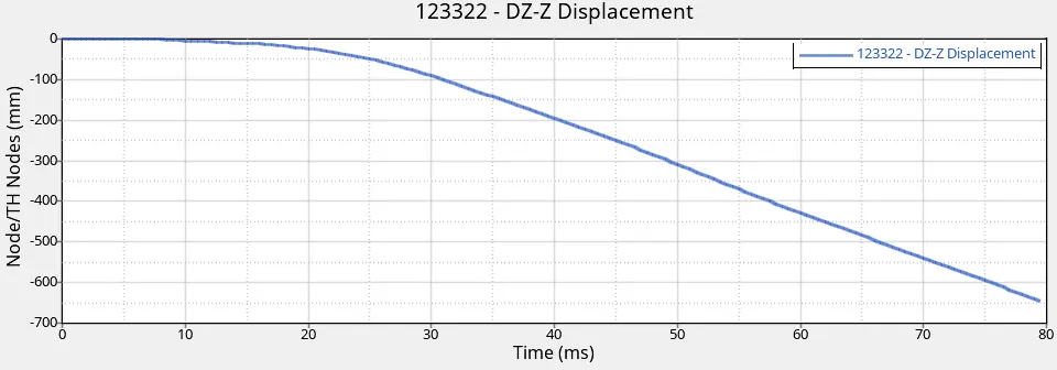
5. The magnitude of intrusion at Hinge pillar is 646.03 mm
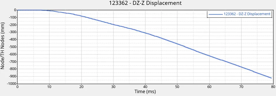
6. The magnitude of intrusion in fuel tank region is 922.78 mm
7. The negative sign indicates that the nodes are moving towards the inside of the BIW frame
8. As a reduced model is used here due to node limitations, the rear axle and the cross beams that support the rear axle are absent.
9. This gives an impression of high intrusion of fuel tank region in the model.
10. But in real life scenario, the rear axle and the cross members supporting the axle impart additional stiffness to the frame and reduce the intrusions to a great extent.
11. But if the intrusions are to be further more reduced, an additional cross member with appropriate axial and bending stiffness must be added to the frame like shown in the picture (Black line)
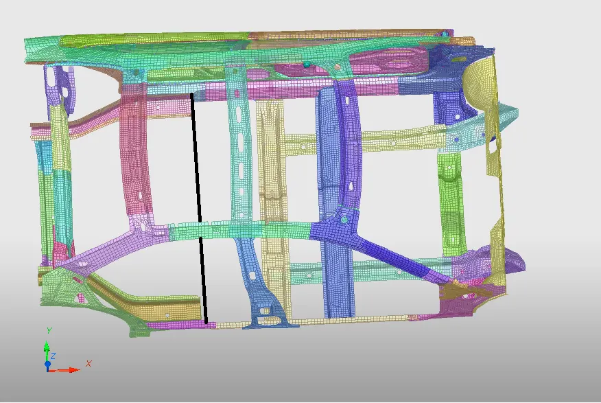
12. But care should be taken while introducing any new cross members as it might lead to increased stiffness of the overall frame which might have a negative effect on force propagation in frame.
Peak velocity of inner node on the door:
1. While the intrusions on the b- Pillar and rear hinge pillar might not directly affect the driver because in most vehicles, the b- pillar is just behind the front seat, there is a high probability of injuries to the torso or legs of the driver due to the inner part of door hitting them.
2. So it is vital to monitor the velocity of impact of the part nearest to the driver, which is, the inner side of door.
3. The peak velocity of the inner node on the door along Y- Axis is 12.87 mm/ms
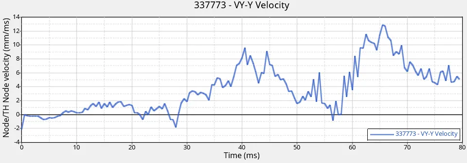
4. The peak velocity along the other axes are relatively low and hence only the peak velocity along Y Axis is taken into consideration
5. Since the force is transmitted in the form of shock waves, occurrence of fluctuations due to vibrations and oscillations like the ones seen in the graph is normal and hence only the peak velocity is measured to study the impact of the door on the driver or passenger.
Result:
Side Pole Impact of the BIW model was simulated and the findings are presented.
|
Output Requests |
Magnitude |
|
|
Sectional forces in cross member (kN) |
Cross member 1
|
7.39 |
|
Cross member 2
|
11.915 |
|
|
Intrusions (mm) |
B- pillar (123408) |
946.52 |
|
Hinge Pillar (123322) |
646.03 |
|
|
Fuel Tank region (123362) |
922.788 |
|
|
Peak Velocity of inner node of door (mm/ms) |
12.87 |
|
Learning outcome:
1. Checking connectivity of parts is very important as failure to do so will yield incorrect results.
2. As the forces transmitted from the point of impact are interrupted when there are unconnected parts, the forces are thus transmitted to other parts which will induce stresses in unrelated parts/components.
3. This abnormal force propagation and stress generation gives misguiding results.
4. While checking for connectivity, the first priority must be for those parts that are in the load path.
5. In some cases, unconnected parts can also cause energy errors.
6. While creating the rigid wall, care must be taken not to add too many slave nodes as it will slow down the simulation.
7. The given problem in the problem statement i.e. reduction of fuel tank region intrusions can be solved by placing another cross member in the region shown in the picture although this method might increase the stiffness of the structure which might be harmful in side crash scenario.
8. Peak velocity of the node on the door is high which may cause serious injuries to the person.
9. The peak velocity of the door can be reduced by using a dampening or cushioning material between the door panel.
10. If the cushioning material cannot be placed within the door panels, the surface of the door panel that makes contact with the person could be covered with a soft material to reduce the severity injuries during impact.
Conclusion:
The given frame’s crashworthiness was tested under the side pole impact simulation scenario, the forces through major load absorbing cross members, relative displacement of important structures and velocity of the inner node of door were studied in detail.
An effective method to restrict the intrusion of the fuel tank region inside frame was also discussed.
Google Drive Link - https://drive.google.com/file/d/1IjaGi2CrHmdPoBI-nSRnohI4LgTazmRN/view?usp=sharing