Side Pole Impact Analysis using Radioss in Hypermesh
AIM :
To test the vehicle crashworthiness by conducting a Side pole impact test as per Standard requirements and evaluate the results by using Radioss in Hypermesh.
OBJECTIVE :
- Check unit system and either follow [Mg mm s] or [Kg mm ms].
- Create an appropriate interface, friction 0.2, and recommended parameters.
- Make sure of no penetration and intersections.
- Create a rigid wall with friction 0.1 as per the reference model.
- Compare the model weight with the reference model and use added masses to reach the target weight of 700kg while getting CG about the required range.
- Initial velocity as shown in the picture.
- Use a model checker to ensure good quality.
- Timestep :0.5 to 0.1 microseconds.
- Run 80ms.
Output Requests :
- Sectional force in the cross member.
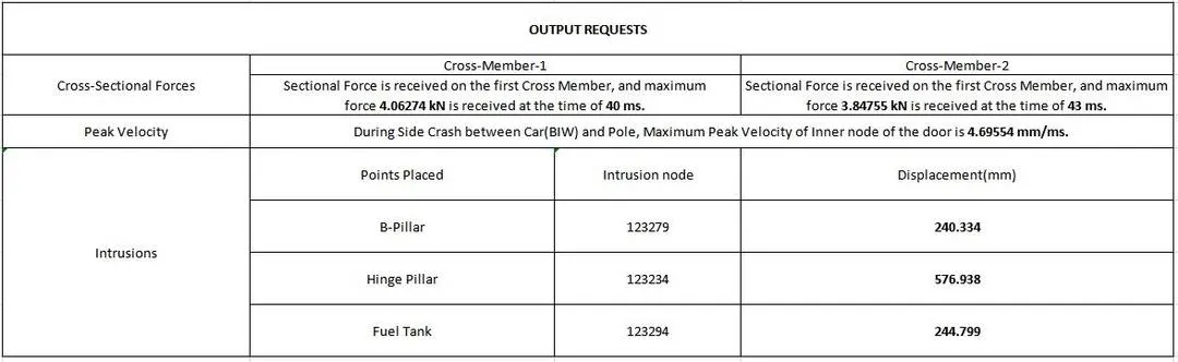
- The intrusion at B pillar, hinge pillar, and fuel tank region. Provide recommendations on what can help to reduce Fuel tank intrusion.
- Peak velocity of the inner node of the door.
THEORY :
Federal Motor Vehicle Safety Standard (FMVSS) 214 :
FMVSS 214, Side Impact Protection, specifies performance requirements for the protection of occupants in side-impact crashes. The purpose of this standard is to reduce the risk of serious and fatal injury to occupants of passenger cars by specifying strength requirements for side doors. This standard applies to all PASSENGER CARS as well as 90% of light truck type vehicles with a GVWR < 10,000 lbs, manufactured on and after September 1, 1993, to August 31, 1994. On and after September 1, 1994, all light truck type vehicles with a GVWR < 10,000 lbs will be required to meet the static requirements.
Head injuries are a major cause of fatalities in side impacts, whereas chest injuries are the predominant cause of AIS 3-5 non-fatal injuries. However, there is no head injury requirement in the dynamic FMVSS No. 214 test. Typically, the moving deformable barrier hits below the dummy’s head, the window breaks, the dummy’s head goes out the window but does not strike the barrier. Thus, the measured head injury criterion (HIC) tends to be low in this dynamic test. Yet, in the real world, many people are killed or seriously injured by head injuries in side impacts.
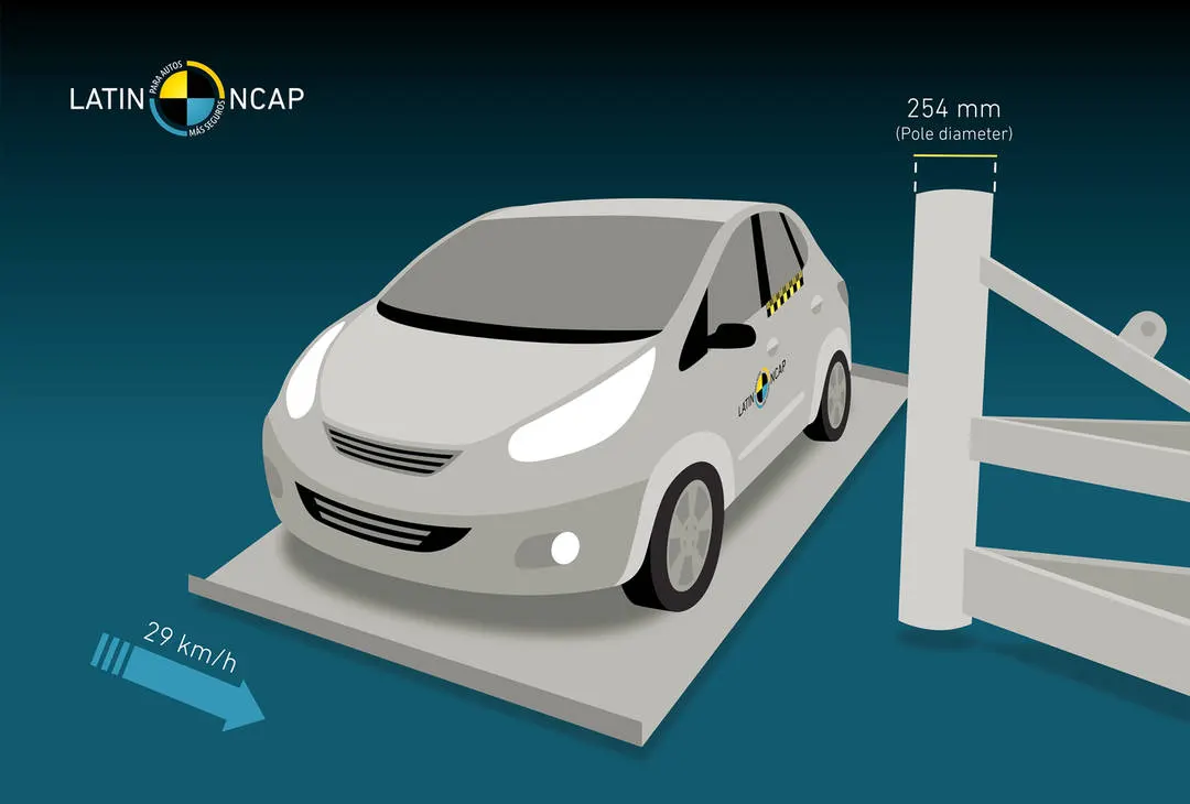
Fig: Side Pole Impact
Even with Standards No. 214 and 201, there are still a large number of fatalities occurring inside impacts resulting from a variety of crash types and outcomes. Fatalities are occurring when an occupant strikes a tree or pole, when the striking vehicle has a high front end (a taller pickup, SUV, or a heavy truck) when the occupant is ejected out the side window, and when the crash is of high speed/ high severity, even when the striking vehicle is a passenger car.
The final rule will substantially upgrade FMVSS 214 by requiring all passenger vehicles with a GVWR of 4,536 kilograms (10,000 pounds) or less to provide protection in a vehicle-to-pole test simulating a vehicle crashing sideways into a narrow fixed object like a telephone pole or tree. The pole test will be conducted using a 5th percentile female dummy (SID-IIs Build D) seated full-forward or a 50th percentile male dummy (ES-2re) seated at the mid-track position of the front outboard driver or passenger seats. The agency is also requiring that the 50th percentile male be used in the front outboard seating positions and the 5th percentile female be used in the rear outboard seating positions in the MDB test configuration required by FMVSS 214.
Test Requirements :
Vehicles have side impacts with a variety of different objects, including poles and trees, and other vehicles of the same or different type as the impacting vehicle. These crashes can pose different risks of injury to vehicle occupants. There is also the risk of injury from being ejected in a side crash, even crashes not involving vehicle rollover. To address these concerns, NHTSA is requiring vehicles to meet an oblique pole test in which the vehicle is propelled into a rigid 254 mm (10-inch) diameter pole. The pole is aimed at the head of a front seat occupant (either the driver or right-front passenger) using crash dummies representing a 50th percentile male (ES2-re) and 5th percentile female (SID-IIs).
Under the FMVSS No. 214 side crash, vehicle crashworthiness is evaluated by conducting a Side pole Impact test as 254mm diameter pole impact on a 90° oriented car, traveling at 29 km/h (18 mph). To meet the test, vehicle manufacturers will need to assure head and improved chest protection in side crashes. It will lead to the installation of new technologies, such as side curtain airbags and torso side airbags, which are capable of improving head and thorax protection to occupants of vehicles that crash into poles and trees and vehicles that are laterally struck by a higher-riding vehicle.
SOFTWARE USED :
- Radioss (in Hypermesh)
PROCEDURE :
1. In Hypermesh, Go to Applications-->open Hypercrash and Import the neon_side_reduced_0000 rad file.
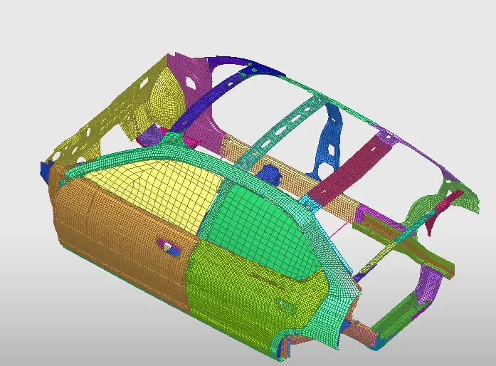
Fig: Imported Model
2. Open neon_side_reduced_0000 rad file in Notepad and Check the Unit System.
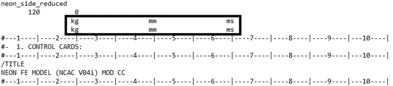
Fig: Unit System
3. In Hypercrash, Right Click on Browsers-->Create New-->A-C-->Contact Interface-->Multiusage(Type-7) option and create appropriate interface with friction 0.2 and recommended parameters.
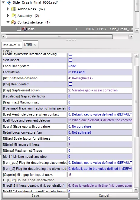
Fig: Type-7 Interface with Recommended Parameters
4. In the Tree window, Select Neon FE Model and Go to Check Intersections of Tree Selection-->Check Penetration icon.
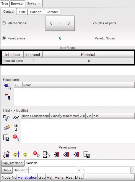
Fig: Penetration Check
5. Creating Rigid Wall by Right Click on Browsers-->Create New-->M-R-->Rigid Wall-->Rigid Walls-->Cylinder option and Select the XM, YM, ZM Point to create a rigid wall, Select Slide-->Sliding with friction and Set Deformation range by assigning Dsearch value.
6. In Standard-FMVSS 214 Pole Impact Test, 254mm diameter pole impact on 90-degree oriented car, traveling at 29 km/h. Set dia as 254mm of Cylindrical Rigid Wall.
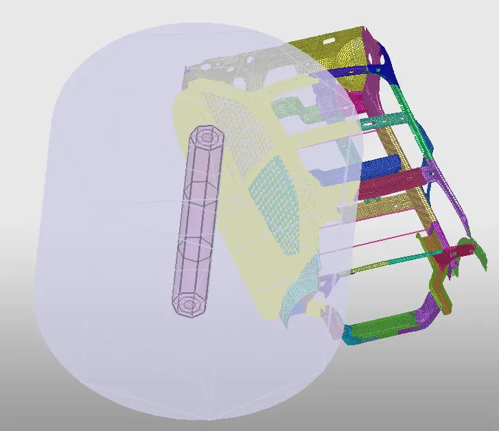
Fig: Rigid Wall Created
7. Comparing the model weight with the full-scale 300k nodes model and use added masses to reach target weight 700kg while getting CG about the required range.
8. Go to Mass-->Balancing Option and check the Mass & CG of the given Model.
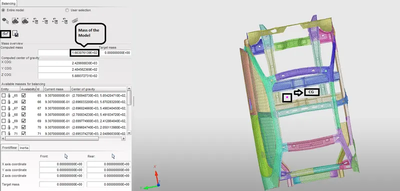
Fig: Mass Balancing
9. Go to Browser-->Added Mass option and Create a new object and add mass on the Component to get CG about the required range.
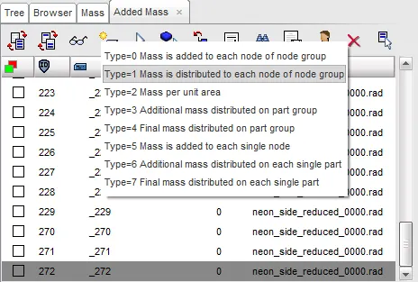
Fig: Added Mass
10. Enter Mass Value in Added mass and Right-click on Support-->Select in graphics-->Add or Remove nodes by picking selection (or) Include picked parts option and add the mass of the given model.
11. By using added masses to reach the target weight of 700kg and got CG about the required range.
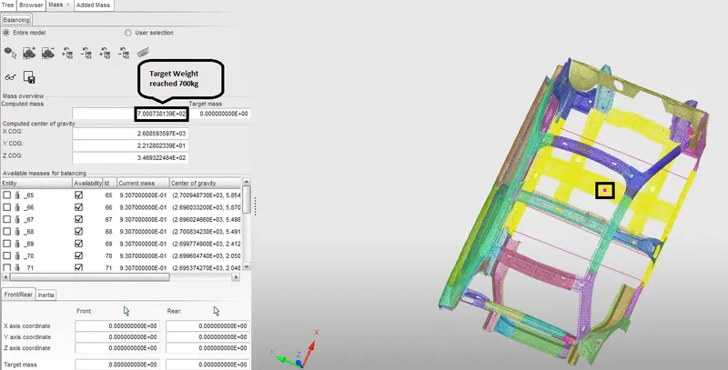
Fig: Target Weight reached and got CG about Required range
12. In Hypercrash, Go to Quality-->Model Checker-->Run option and Check if there is an error that occurred in the model.
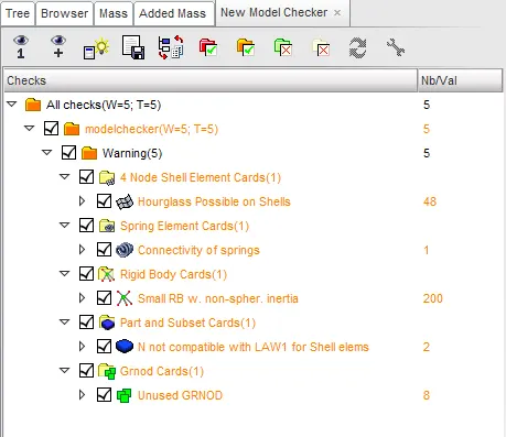
Fig: Model Checker
13. From the above figure window, it shows 0 Error and 5 Warnings are negligible.
14. In-Browser window, Right Click-->Create New-->I-H-->Initial Velocity option and select the grnd_ID and Enter the Velocity value in Y Velocity.
15. As per FMVSS 214- Pole Impact Test Standard Regulation, assumed Initial Velocity as 29km/h(8.055 mm/ms)
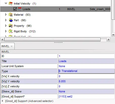
Fig: Initial Velocity
OUTPUT REQUESTS :
Sectional Force in the Cross Member :
1. Creating Sectional Force in the Cross Member,
2. Go to Browser--> Right Click-->Create New-->S-Z-->Section-->Default Section option.
3. Select Node N1,N2,N3 and in grshel_ID select elements,in grtrainID select tria elements.
4. In Frame Right Click-->Create Frame and Select Origin, X-axis, Y-axis Co-ordinates and Click OK.
5. Set Time Step for saving the data(Dt) as 0.1.
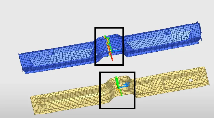
Fig: Sectional force in the Cross Member
Intrusions at B Pillar, Hinge Pillar and Fuel Tank region :
6. Creating Intrusions at B Pillar, Hinge Pillar, and Fuel Tank region.
7. In-Browser-->Right Click-->Create New-->D-H-->Data History-->TH of nodes option and Select the node on B Pillar, Hinge Pillar, and Fuel Tank region.
8. Create Spring between selected nodes and similar to the Opposite nodes, by creating a new property.
9. Selecting type as P4_SPRING and set Spring mass as 0.01, Stiffness as 0.01.
10. In Part, Create New Part as Spring and assign the Spring Property in Property.
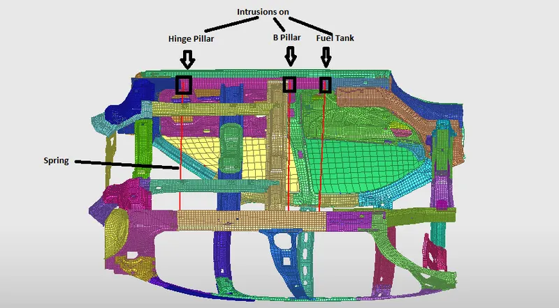
Fig: Intrusions at B Pillar, Hinge Pillar and Fuel Tank Region
Peak Velocity of the inner node of the door :
11. Getting Peak Velocity of the inner node of the door,
12. In-Browser-->Right Click-->Create New-->D-H-->Data History-->TH of nodes option and Select the inner node of the door and Click Save.
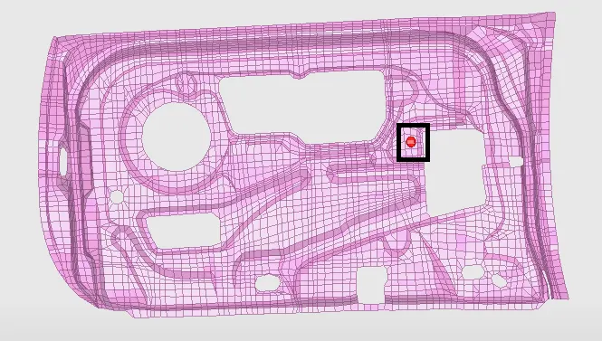
Fig: Selected Inner node of the door for Peak Velocity
13. Finally Export the Model by using the File-->Export-->Radioss option and Save the Model.
14. In Hypermesh, Import the Saved Model and Go to Solver-->Engine Keywords-->DT-->DT/NODA option and Enter Time Step between 0.5 to 0.1 microseconds
15. Go to Solver-->Engine Keywords-->RUN-->ENG_RUN option and Enter the Simulation Run time as 80 ms.
PLOT RESULTS :
Contour Plot :
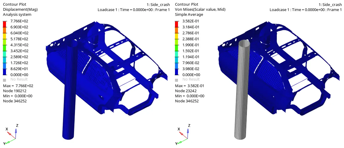
From the above contour plots observed that,
Car is crashed on to the Cylindrical Rigid Pole at the initial velocity of 8.055 mm/ms. With the help of Hypermesh(in Hyperwiew mode) Contour plots are displayed above. From the Contour plots, accurate results will be obtained.
- A Displacement plot shows the motion of an object in a direction perpendicular to its surface. From the Displacement, the plot observed that during Frontal Crash Deformation will occur, and Maximum Displacement is 7.766E+02.
- The von Mises stress is used to predict the yielding of materials under complex loading from the results of uniaxial tensile tests. The von Mises stress satisfies the property where two stress states with equal distortion energy have an equal von Mises stress. The Vonmises Stress plot shows that, While Deformation occurs, Stress will be created and Maximum stress is 3.582E-01`N/(mm)^2`.
Sectional Force Plot :
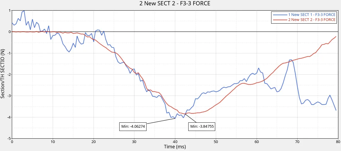
Cross-Section force is an internal force determined in the proper cross-section co-ordinate system. The cross-Section is created on the two cross members. During Crash event Cross Member gets deformed,
- Sectional Force is received on the first Cross Member, and maximum force 4.06274 N is received at the time of 40 ms. The frame is created on the Cross-Section, so it shows in a negative direction based on the proper cross-section local coordinate system.
- Sectional Force is received on the first Cross Member, and maximum force 3.84755 N is received at the time of 43 ms. The frame is created on the Cross-Section, so it shows in a negative direction based on the proper cross-section local coordinate system.
Intrusion Plot :
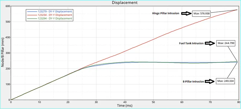
Three nodes of Intrusion were considered to find the displacement of three nodes from the analysis of the side crash, the simulation test configurations are evaluated based on the energy absorbed by the vehicle structure during the crash event. From the above Intrusion plot, we observed that the selected nodes are get displaced during the side crash and the displacement value is mentioned below.
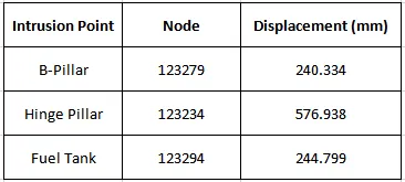
During Side Crash between Car(BIW) and Pole, Pole is impacted on the B-Pillar. So that, Intrusion on B-Pillar is lower than Hinge Pillar and Fuel Tank.
Peak Velocity Plot :
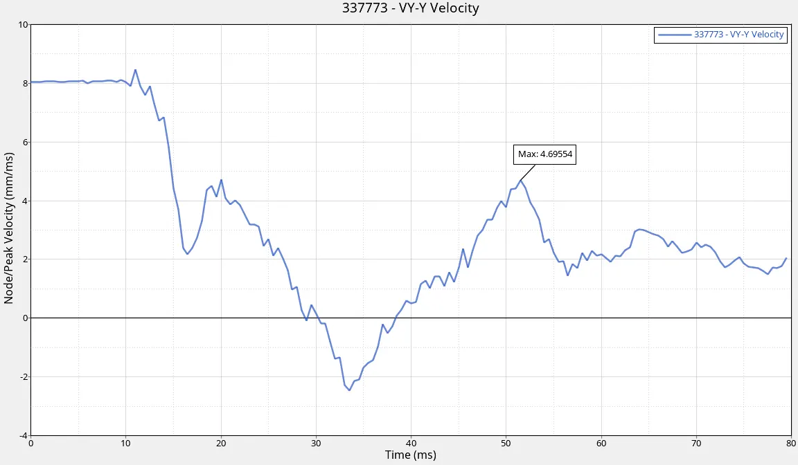
Peak Velocity is the highest velocity attained during the same concentric lift phase. It's a single point and will always be a much higher number than the mean.
- During Side Crash between Car(BIW) and Pole, Maximum Peak Velocity of Inner node of the door is 4.69554 mm/ms.
Energy Plot :
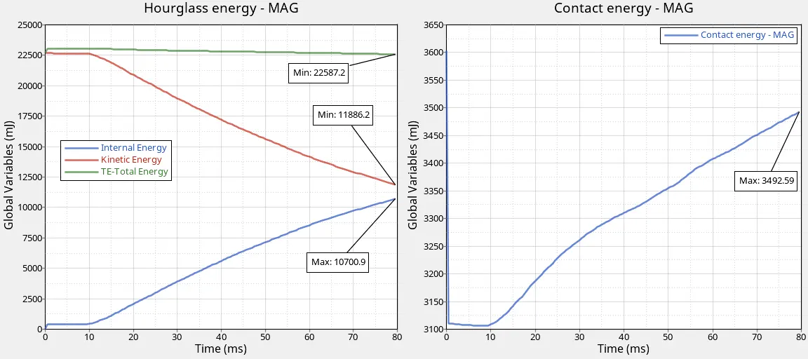
From the above Energy Plot we observed that,
- For the first 10 ms there is no crash between BIW Component and Pole After 11 ms Side Crash starts and Internal Energy starts to gain the energy of the system due to changes in its internal state, and Maximum Internal Energy is 10700.9 mJ is generated.
- The Maximum Kinetic Energy of the system is at t=0ms(no deformation at the time), Kinetic Energy starts to lose the energy of the system at t=10ms, and at t=80ms Kinetic Energy is 11886.2 mJ.
- We Know that Total Energy remains constant(no loss or generation of energy), Kinetic Energy decreases while Internal Energy Increases. So that Total Energy is 22587.2 mJ at t=80ms.
- Contact Energy is a Combination of Penetration and Contact Force (between Master & Slave Nodes). For the first 10 ms, there is no crash between BIW Component and Rigid Wall, After 11 ms Side Crash starts and Contact Force is a force applied between Master & Slave nodes and energy required to resist the Penetration of Master & Slave Node So that Contact Energy is increased up to 3492.59 mJ.
ERROR RESULT :
1. After Running the Simulation, Open the Engine OUT File from the saved folder and Check the Energy Error & Mass Error.
2. Energy Error is -0.0%(better to have within -5%) and Mass Error is 0.00004787%.
CONCLUSION :
As per FMVSS No.214 requirement Side Impact Protection, vehicle crashworthiness is evaluated by conducting a Side crash test into a Cylindrical rigid pole at an impact speed up to 8.055mm/ms (29 mph). Energy Error, Mass error, Total Simulation run time, Displacement, Vonmises stress, Energy Absorption, Cross-sectional forces, Axial force, Intrusions have been evaluated during crash simulations, and results were displayed.