Assignment 6-Frontal Crash Simulation Challenge
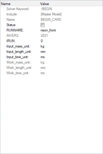
- Check unit system and either follow[Mg mm s] or [Kg mm ms].
opening the BEGIN CARD. The unit used in model is specified.
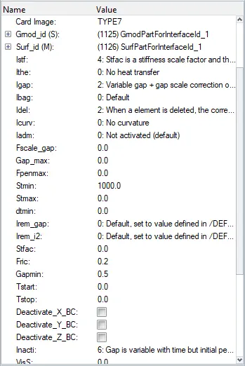
- Create appropriate interface ,friction 0.2 and recommended parameters.
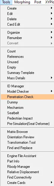
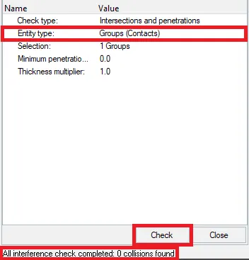
- Make sure of no penetration and intersections.
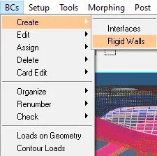
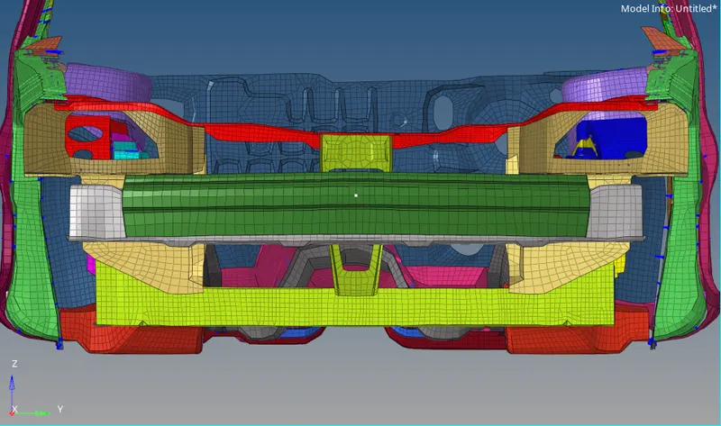
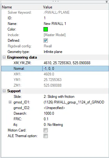
- Create rigid wall with friction 0.1 as per referance model.
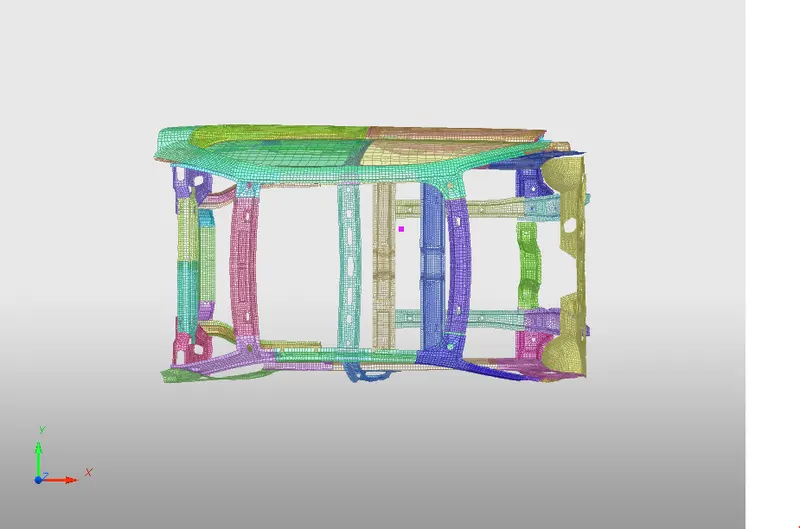
- Compare the model weight with the referance model and use added masses to reach target weight 700kg while getting CG about the required range.
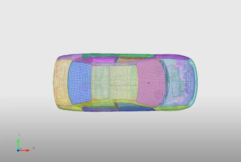
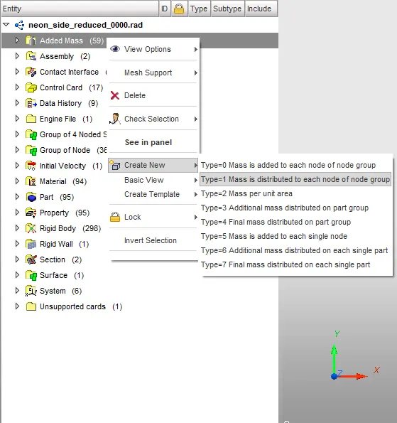
Right clicking on the added mass-> create new selecting type 1
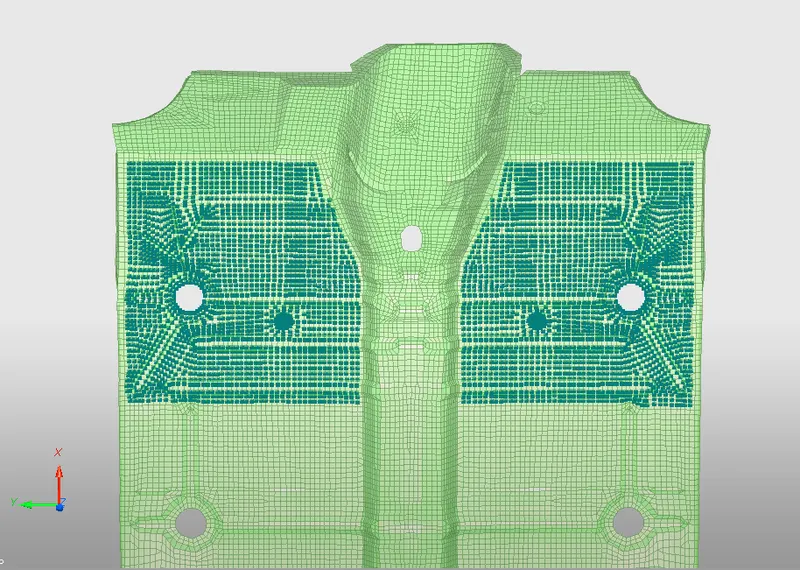
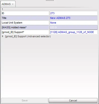
selecting the nodes on which the masse where to be added. the highlighted nodes are the ones on which the masses was added. weights were added to 4242 nodes and a individual weight of 533.9 was added, which added upto the car having a total weight of 700kg.
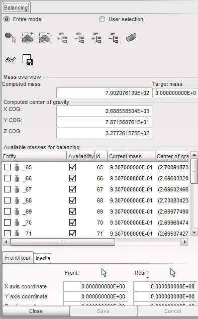
the cog of the car is a very important parameter. in this the assignment only the x-y orientation of the cog is important and height of the cog doesnt matter.
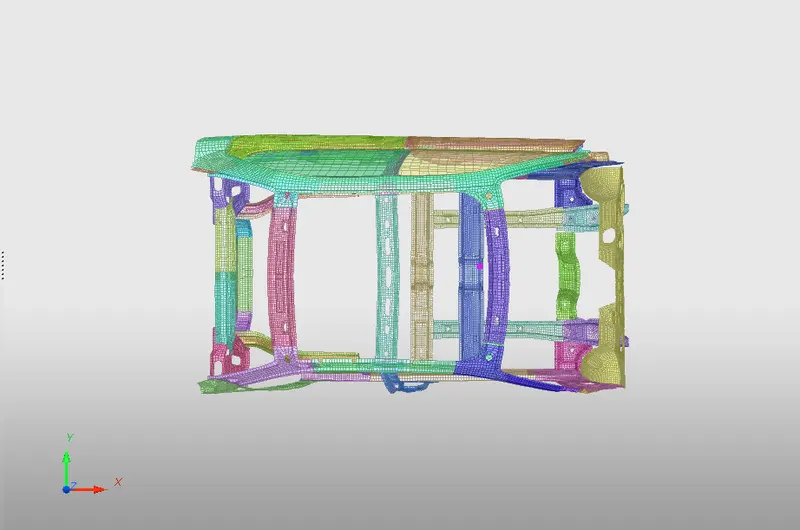
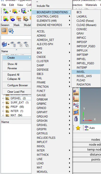
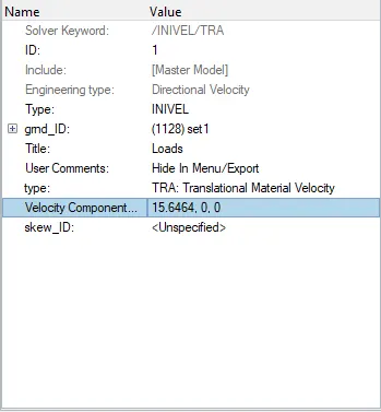
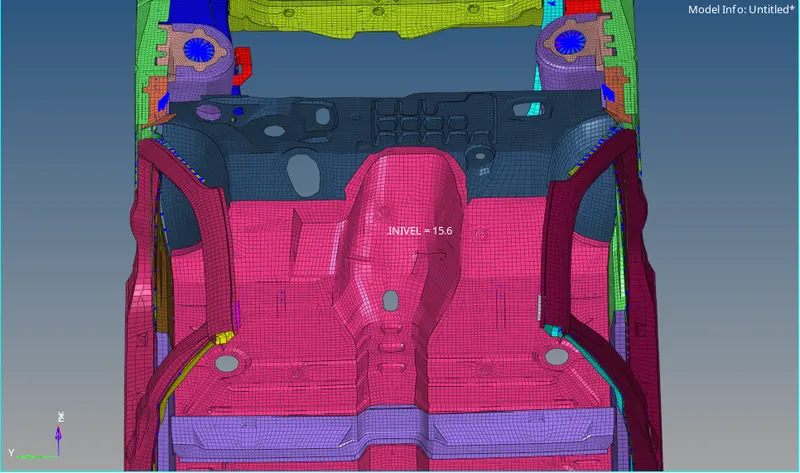
- Initial velocity as shown in picture.
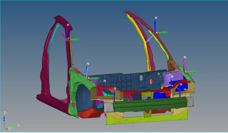
- Sectional force in the rails at location of indicated node 174247.
- Axial force received on the rails from bumper.
- Shotgun cross sectional forces.
- A pillar cross section.
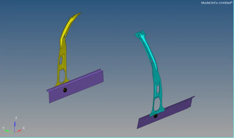
to get the forces in these section we need to have frames and sectional defined at those particular places.
creating a frame
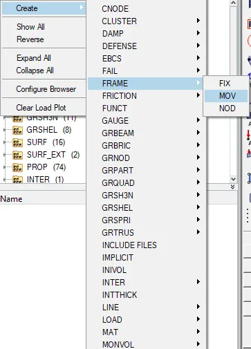
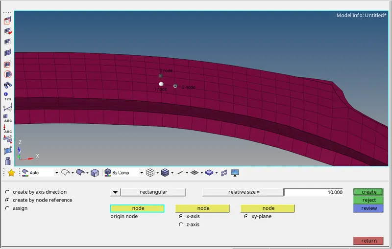
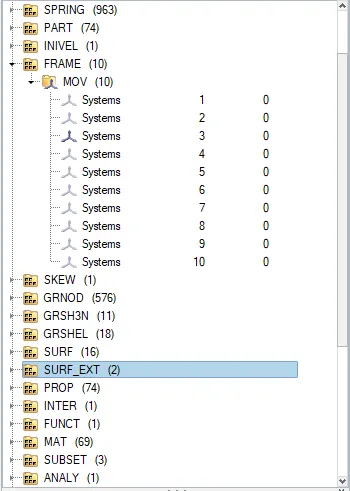
after creating frames we will create section
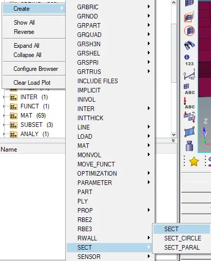
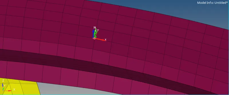
select the nodes in the same order as we selected the nodes for the frames
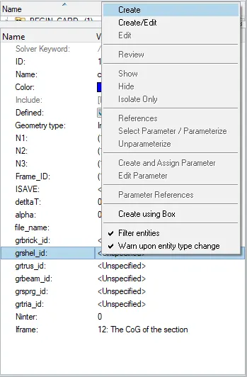
create a set(grshell id)
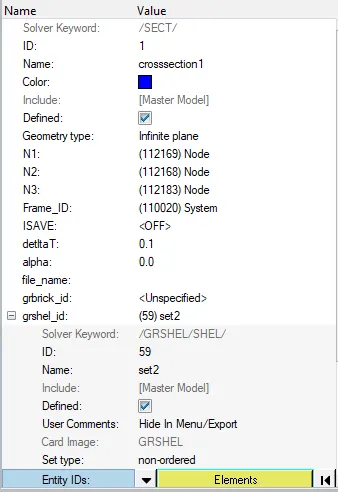
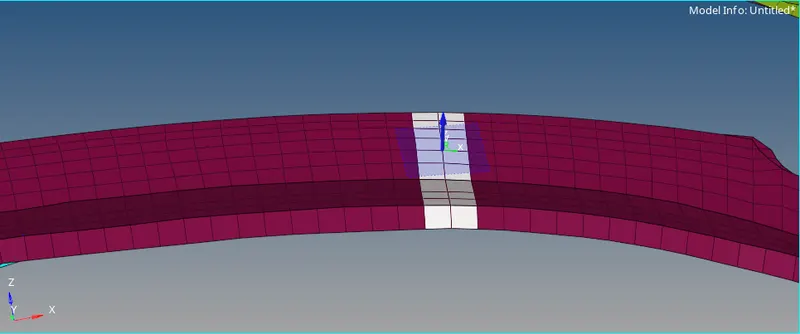
select the elements which will define a proper crossection.and select iframe as 12
continue these step and create frame and section where ever required.
- Sectional Forces at Shotgun
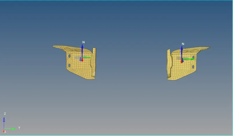
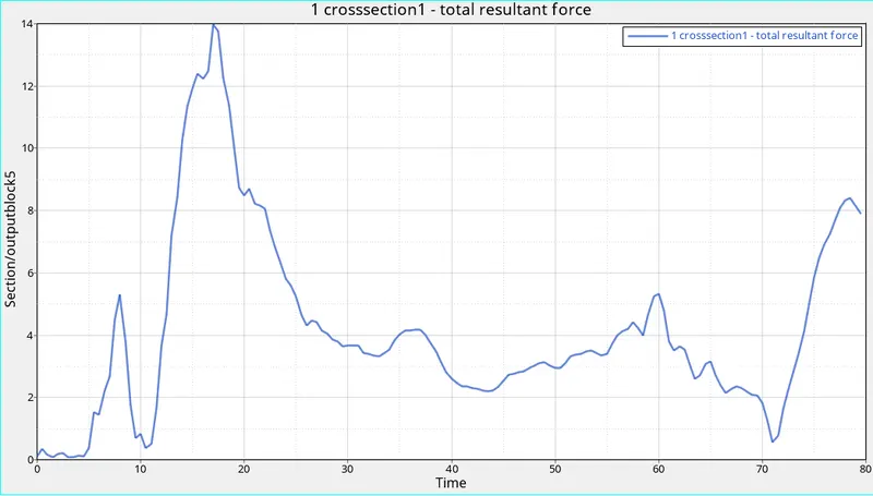
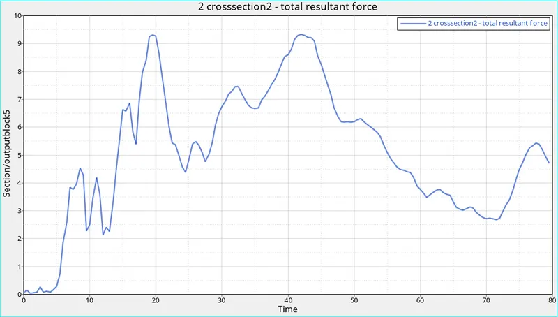
- The difference in the force profile between the to graphs are due to the pitching yawning and absence of engine block and structural reinforcements.
- We can see that right side of the car experiences more deformation and resultant forces compared to the left side.
- From the graph of the left side shotgun we can see that the left side under goes only one peak where as the rigth ide under goes 2 major peaks.
- This suggest that the right experiences jerk more often than the left side.
- The left side experiences a higher peak when compred to the right side(13.97KN, 9.321KN).
- The reason for the increase of the forces in the right side is due to the improper deformaion of the element of the right shotgun.
- Sectional Forces at Rails
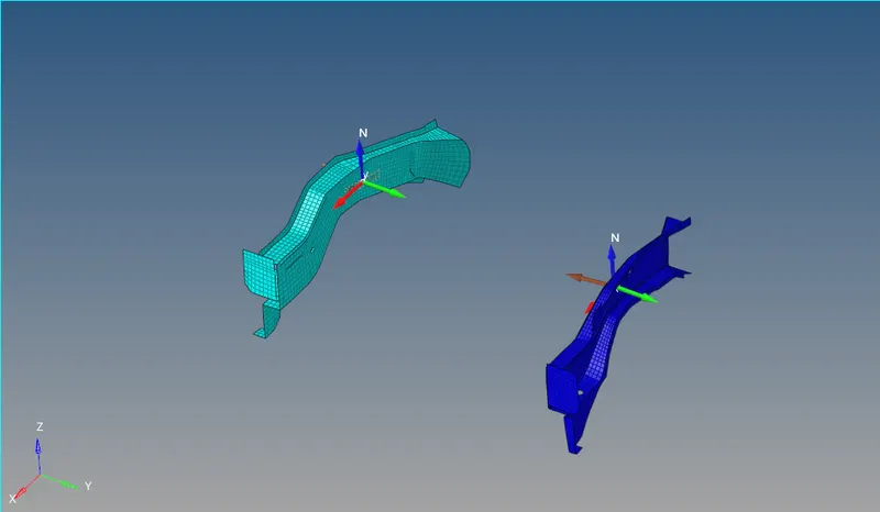
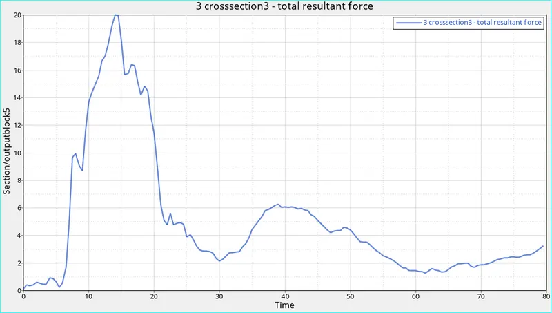
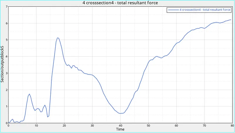
- The forces in lhs rail reaches its peak value of 20KN at 14ms.
- It has many smaller peaks for the rest the of the simulation telling us that only one major impulse or jerk was experienced during the simulation.
- Due to the yawning effect the pillars under goes self penetration due to which the forces increases after the initial impact.
- In the rhs rail the peak is much smaller than the left side.
- From the graph we can say that the right side rail experiences a much severe deformation compared to the left side.
- Sectional Forces at Fender
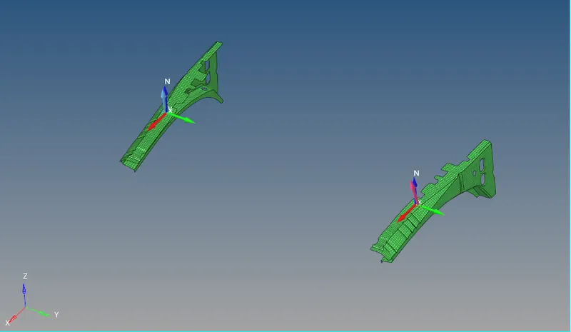
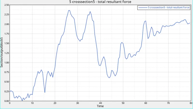
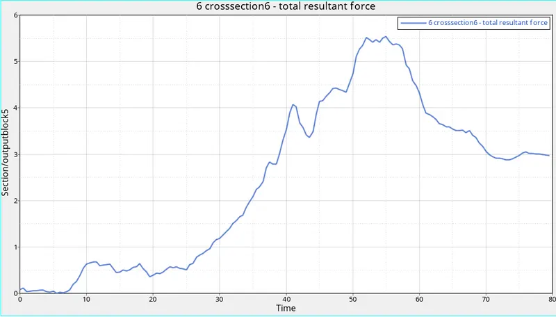
- Due to the yawning effect the pillars under goes self penetration due to which the forces increases after the initial impact.
- From the simulation we can see that the right side of the car goes under more deformation.
- The peak forces experienced by the l.h fender is 2.35742KN and by r.h fender is 5.53722KN.
- The left side fender experiences 2 major jerks between 25ms and 40ms. the forces decreases till 44ms, after which it increases again but less rapidly.
- The right side fender expeiences almost the double the forces as the left side fender.
- Sectional Forces at A Pillar
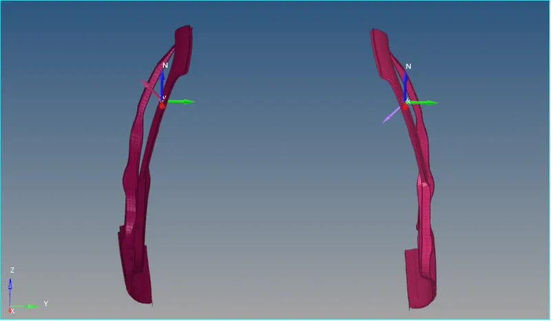
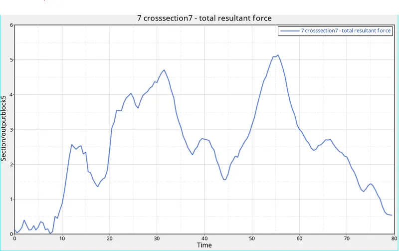
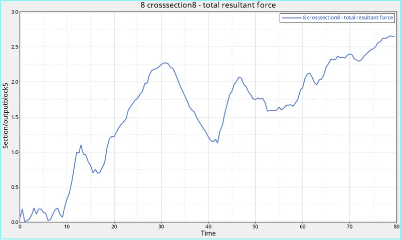
- The majority of the the forces experienced by a pillars are the forces induced by the self penetration of the fender and the rails.
- The forces produced by the impact is more experienced by the fender, rails, shotgun as the stress and forces involved are much higher in those areas.
- The left side a-pillar experiences more force than the right side a-pillar.
- Max force experienced in the left side is 5.1388KN and left side a-pillar is 2.65667KN.
- Left side experiences multiple higher impulses of higher magnitude when compared to the right side.
- In the right side a-pillar the forces increasisng through out the simulation due to the improper deformation of the rail fender.
- Sectional Forces at Hinge Pillar
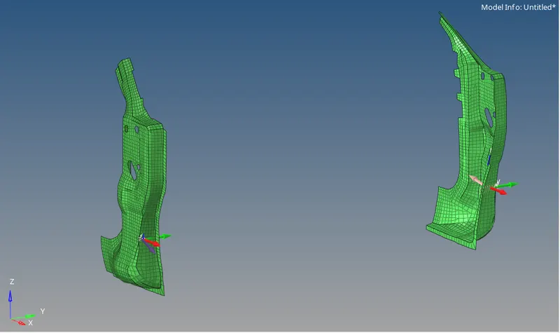
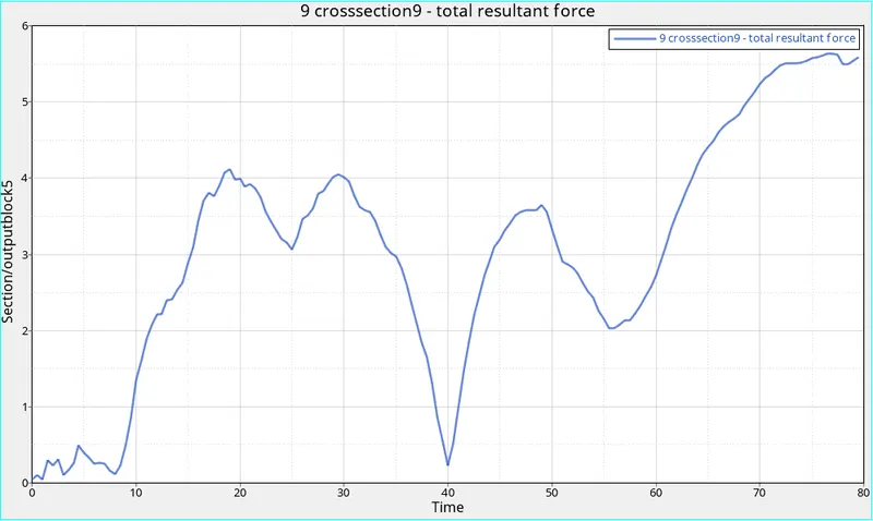
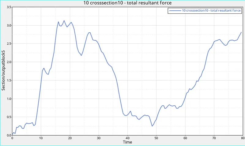
- From the graphs we can say that the forces circulating through hinge pillar is very low
- Acceleration curve received on the accelerometer at base of B pillar (on B pillar rocker).
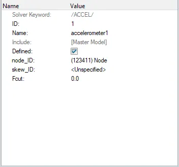
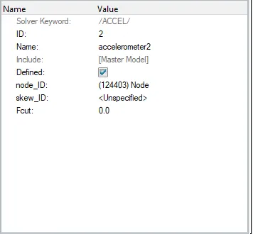
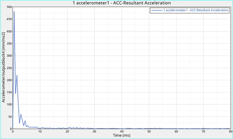
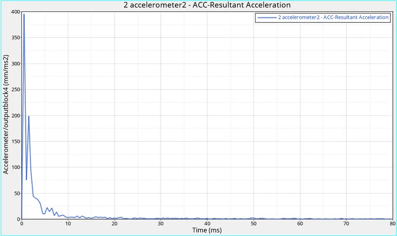
- From the graphs above we can say that only one major jerk due to the impact is caused.
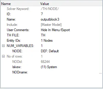
- Intrusions on the dash wall 66695,66244.
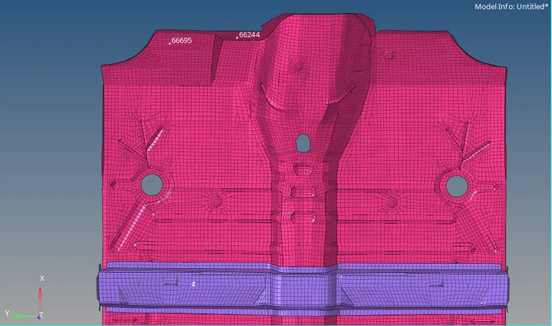
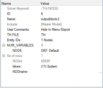
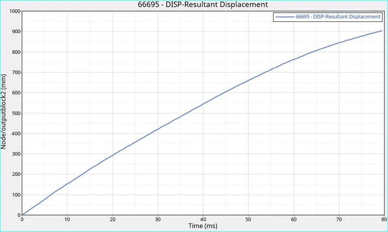
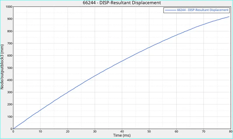
the intrusion of 900mm is within the limit and doent causes any major injury to leg.
h3d files
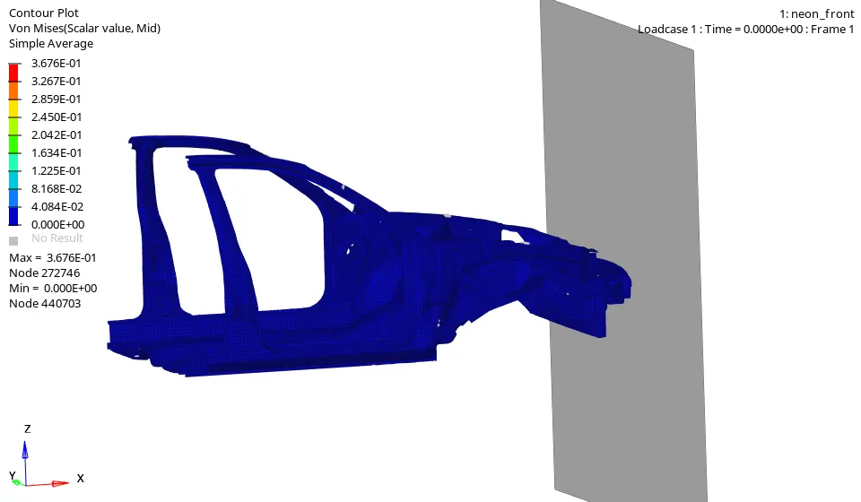
we can see that the car is pushed upward due to the obvious absence of the engine block and other reinforcement structures. Major stress and forces are experienced by the shotgun, rails and fender as we can see. the upward deflection of the car produces extra stress and forces due to the self penetration.
Plot energies
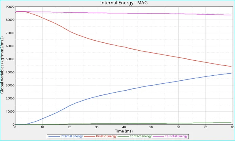
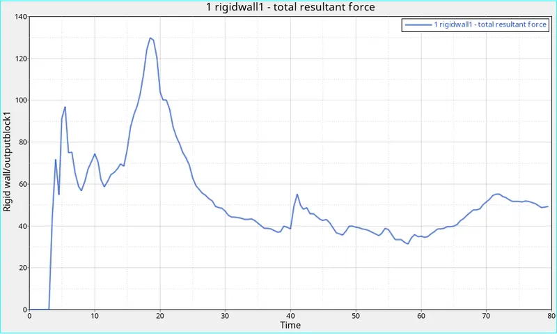
we can say the max rigid force happens when the front part of the car makes the initial impact and start to deform around 18ms mark. as the deformation of thr car continues the force decreased as forces travel across the car.
| No of Cycles | 80,000 |
| Energy Error | -1.1% |
| Mass Error | 0.4885E-01 |
| Max Total Energy | 83620.04J |
| Max Internal Energy | 39246J |
| Max Kinetic Energy | 86154.1J |
| Max Contact Energy | 1508.16J |
| Rigid Wall Force(Max) | 129.779KN |
| Components | Left Side | Right side |
| Shotgun | 13.9701KN | 9.32142 |
| Rails | 20.00KN | 6.20997KN |
| Fender | 2.35742KN | 5.53722KN |
| A-Pillar | 5.13838KN | 2.6416KN |
| Hinge Pillar | 5.63513KN | 3.1304KN |
| Accelometer | 480.961`(mm)/(ms^2)` | 395.272`(mm)/(ms^2)` |
| Intrusion | 904.487 mm | 918.663 m |
conclusion:
- The simulation is not of the superior quality as the model used is a reduced model
- Max forces are found in the rails
- Intursion found are found in the safe category.
- Accelerometers shows the initial jerk when the car comes to the virtual stop during the impact.