Frontal Crash Simulation of Dodge Neon
Objective:
To perform a frontal crash simulation of a car using RADIOSS solver.
Softwares used: Hypermesh, Hypercrash, RADIOSS, Hyperview, Hypergraph 2D
Introduction:
A crash simulation is a virtual recreation of a destructive crash test of a car or a highway guard rail system using a computer simulation in order to examine the level of safety of the car and its occupants. Crash simulations are used by automakers during computer-aided engineering (CAE) analysis for crashworthiness in the computer-aided design (CAD) process of modeling new cars. During a crash simulation, the kinetic energy, or energy of motion, that a vehicle has before the impact is transformed into deformation energy, mostly by plastic deformation (plasticity) of the car body material (Body in White), at the end of the impact.
Data obtained from a crash simulation indicate the capability of the car body or guard rail structure to protect the vehicle occupants during a collision (and also pedestrians hit by a car) against injury. Important results are the deformations (for example, steering wheel intrusions) of the occupant space (driver, passengers) and the decelerations (for example, head acceleration) felt by them, which must fall below threshold values fixed in legal car safety regulations.
In response to the crashworthiness tests becoming stricter cars have evolved and they tend to be based around the concept of having a collapsible outer structure that will absorb energy at a constant rate, in essence, dissipate the energy of the crash to protect the passenger. The second part is the vehicle will have a very rigid structure around the passengers which will then transmit the forces around them rather than through them as well as preventing the incursion of foreign bodies.
Case setup:
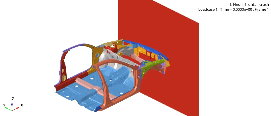
For this simulation, a reduced model of the Dodge Neon car is given, as shown in the image below.
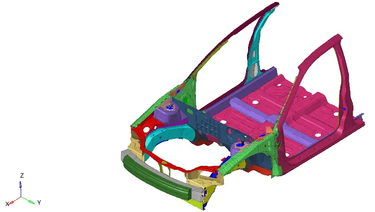
All the connections, materials, and properties are already deployed for this model as per the recommendations for the crash analysis.
The unit system used throughout the system is [kN Kg mm ms].

Interfaces:
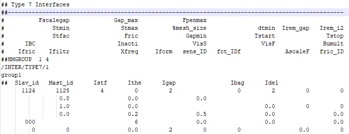
All the previous interfaces are deleted from the model. And, a new TYPE 7 interface is created. All the components are selected as both master and slave components. Recommended parameters used for TYPE 7 contact are as follows,
| Parameter | Comment |
| Istf | = 4, Interface stiffness is the minimum of the master and slave stiffness. |
| Igap | = 2, Variable gap + gap scale correction of the computed gap. |
| Idel | = 2, When an element is deleted, the corresponding segment is removed from the master side of the interface. |
| Fscale_gap | = 0.8, Gap scale factor. |
| Stmin | = 1, Minimum stiffness in the contact to avoid too soft contact. |
| Fric | = 0.2, Coulumb friction. |
| Gapmin | = 0.5, Minimum gap for impact activation. |
| Inacti | = 6, Gap is variable with time, but the initial gap is adjusted (the node is slightly depenetrated). |
| Iform | = 2, Stiffness (incremental) formulation. |
The TYPE 7 contact card created is shown in the image below,
Mass balancing and COG:
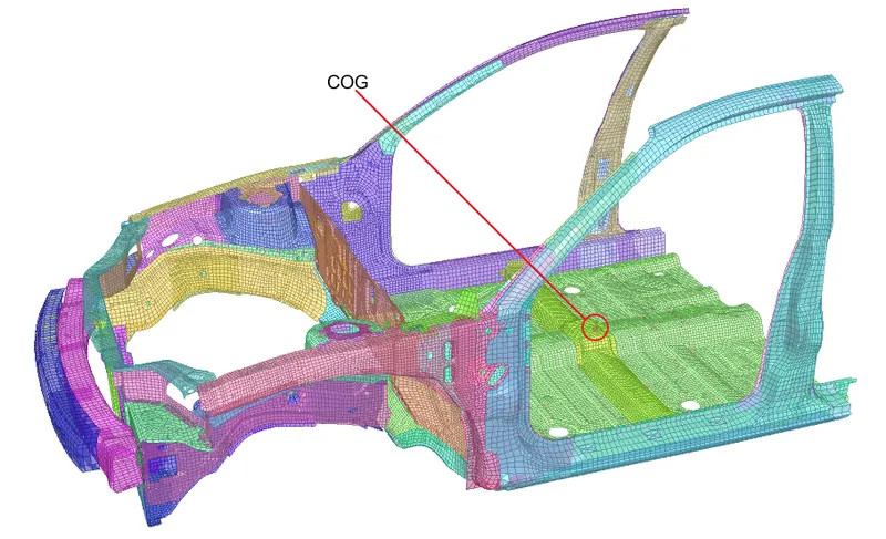
As the given model is a reduced model derived from a full car model, the current COG doesn't lie in its actual position. Also, a lot of other components are removed from the model, therefore the mass is also low. Therefore, to capture the crash behavior properly, we need to match the COG of the car model to its actual position using mass balancing and increase the overall weight of the car model to 700Kg. This is done by adding mass to the nodes of the floor panel using 'ADMAS'.
The new COG is aligned near the driver, as shown in the image below,
Sectional forces:
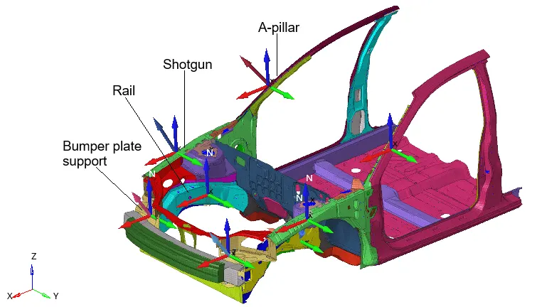
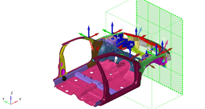
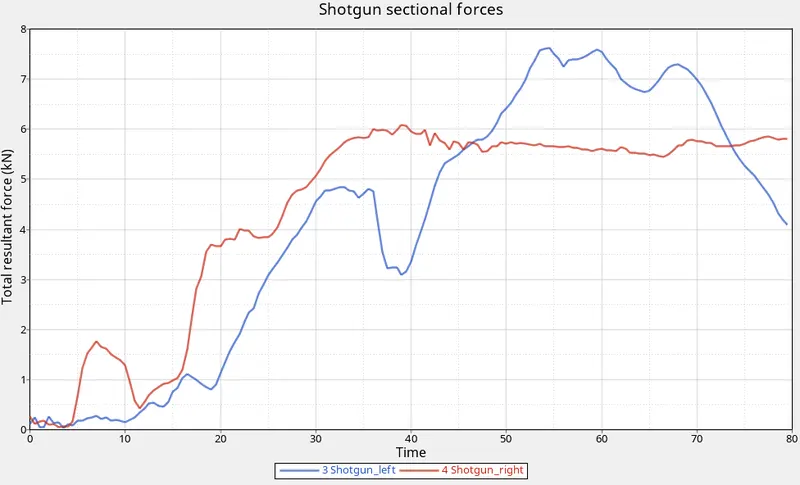
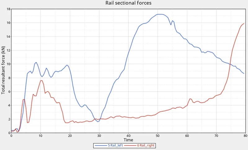
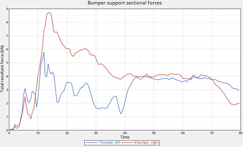
Next, sections are created with local moving frames to measure the forces passing through these sections at the following locations:
- A-pillar right
- A-pillar left
- Shotgun right
- Shotgun left
- Rail right
- Rail left
- Bumper support right
- Bumper support left
Intrusions:
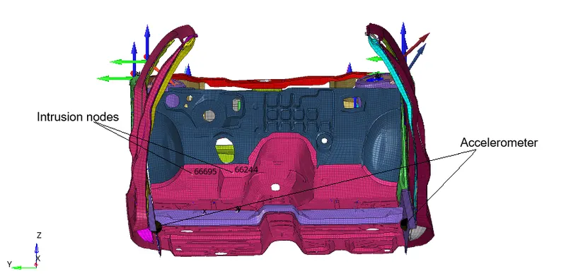
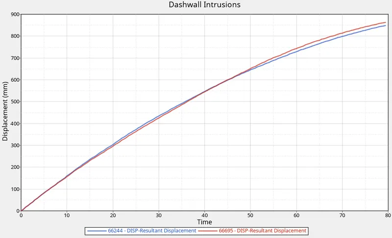
Next, we need to measure the intrusions of dashwall into the driver compartment. For that, two nodes (node id: 66695,66244) are added to time history with reference to a moving skew system.
Accelerometer:
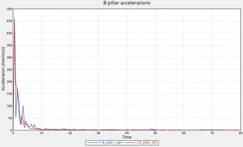
Next, accelerometers are deployed below the B-pillars (on B-pillar rocker) to measure the acceleration during crash.
Boundary condition: INIVEL:
Next, an INIVEL card is configured to give initial velocity of 35mph (15.64 mm/ms) in -x direction to the complete car model.
Rigid wall:
Next, an infinite rigid wall is created in front of the car model as shown in the image below. Search distance is set to 1000mm and friction coefficient is 0.1.
Checks:
- Penetration check: Next, complete model is checked for penetration and intersections using Tools>Penetration Check tool in Hypermesh. All the penetration and intersections need to be removed. There were no penetration and intersections found in this model.
- Connectivity check: The model is checked for connectivity issues in Hypercrash. As this model is derived from a full car model, there is possibility of components which are not required in this model and are not connected. Such components were removed from the model.
- Model check: Next, the the complete model is checked for any errors in Hypercrash before running the simulation. There were some empty sets and those were removed from the model.
Output request:
The time history is requested for the following:
- Parts
- RWALL (rigid wall)
- Dashwall intrusions
- Accelerometers
- Sections
Time step:
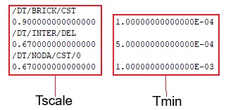
The time step is requested to be 0.5 to 0.1 microseconds. The image below shows the time step parameters configured in the engine file,
Simulation time: 80ms
Results:
- Solving time: 4267.42s (01:11:07)
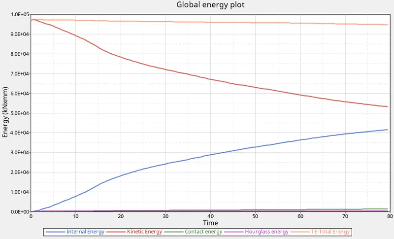
- Energy error: -1.1%
- Mass error: 0.03
Both energy error and mass error are very low and within acceptable limits. Therefore, the simulation results are acceptable.
Crash Animation:
Global energies:
Rigid wall forces:
Dashwall Intrusions:
Sectional forces:
B-pillar accelerations:
| Variable | Peak Value |
| Global Total energy | 97572 kN-mm @0.5ms |
| Global Kinetic energy | 97572 kN-mm @0.5ms |
| Global Internal energy | 41582.7 kN-mm @79.5ms |
| Global contact energy | 1407.54 kN-mm @79.5ms |
| Global Hourglass energy | 452.83 kN-mm @79.5ms |
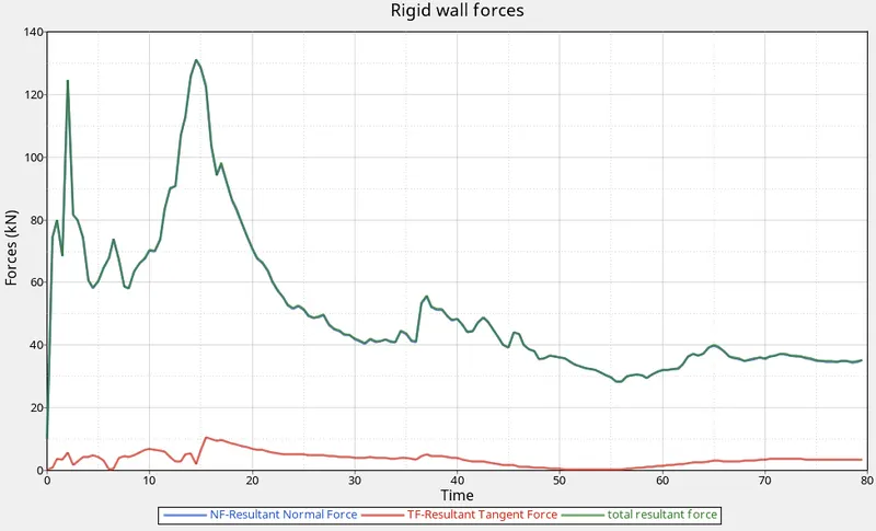
| Net Rigid wall forces | 131 kN @14.5ms |
| Dashwall intrusion (node: 66244) | 849 mm |
| Dashwall intrusion (node: 66695) | 864 mm |
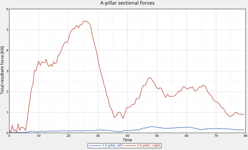
| A-pillar net sectional force (right) | 5.4 kN @25.5ms |
| A-pillar net sectional force (left) | 0.3 kN @48ms |
| Shotgun net sectional force (right) | 6.8kN @39ms |
| Shotgun net sectional force (left) | 7.63 kN @54.5ms |
| Rail net sectional force (right) | 16 kN @79.5ms |
| Rail net sectional force (left) | 17.24 kN @50ms |
| Bumper support plate net sectional force (right) | 8.75 kN @14ms |
| Bumper support plate net sectional force (left) | 5.78 kN @12ms |
| B-pillar net acceleration (right) | 459.34 mm/ms^2 @0.5ms |
| B-pillar net acceleration (left) | 443.83 mm/ms^2 @0.5ms |
Conclusion:
- Global energy plots showed expected behavior. Most of the kinetic energy is converted to internal energy and the total energy remains almost constant during the simulation. Hourglass energy and contact energy are both very low.
- Dashwall intrusions are very high and therefore not safe for the driver.
- Net sectional force in the right A-pillar is much higher than that in the left one. Therefore, we can conclude that the driver compartment is safer from the viewpoint of the A-pillar as most of the force due to impact is already absorbed in the crumple zone.
- Net sectional force in the left shotgun is higher than in the right one. Similarly, net sectional force is higher in left Rail than in the left one. And, the net sectional force in the right bumper support plate is higher than in the left one. Therefore, the energy absorption due to impact is uneven for the left and right sides of the car.
- B-pillar accelerations represent the acceleration that will be faced by the occupants. The B-pillar accelerations at their peak are very low and safe.
- Overall simulation results are not accurate as we are using a reduced car model and can be improved with a complete and detailed car model.
Occupant safety is one of the major focuses in the current automotive industry. The objective of the crashworthiness exercise is to design and develop a vehicle that is safe for its occupants in an event of a crash. To keep the occupants safe, most of the energy due to impact should be absorbed by the car and the passenger compartment shouldn't be deformed and have minimal intrusions. This is achieved by designing crumple zones. Crumple zones are designed both at the front and the back of the car. The main purpose of the crumple zones in an event of a crash is to absorb most of the energy by plastic deformations.
Note: Due to a large file size, only .rad, .out and T01 files are attached.