Assignment 6-Frontal Crash Simulation Challenge
Aim:-
- To set up the given simulation conditions on the BIW model for frontal crash simulation in HyperMesh/RADIOSS and discuss the
results obtained.
Procedure:-
- The model is imported using the import option in HyperWorks.
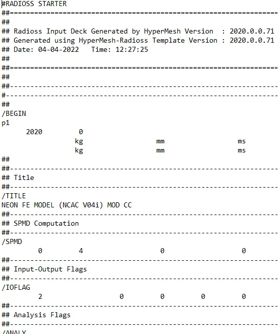
- The unit system is checked in the rad file and it is found to be kg mm ms.
- Initially, the penetrations are checked using the check all solver contact interfaces option.
- Using added mass option in the hyper works additional mass is added for the passenger, driver, and trunk portion of the car, and
the total mass of about 700kg is achieved and the COG point is placed properly. 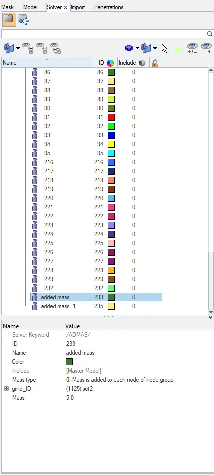
- Penetration is defined as the overlap of the material thickness of shell elements, while Intersection is defined as elements that
actually, pass completely through one another. - All models and especially impact models should be checked for penetrations and intersections to make sure there is no penetration
and intersection. - Penetrations adversely affect results and should be removed.
- To check penetration and intersection Go to tools > Click on check penetration
- We can clearly see from the above figure that there are no penetrations and intersections present in the model.
Create Self Contact:-
- Type-7 Node to surface contact is used in this model. Both the Slave nodes and the Master nodes will be the same for this simulation
since there is self-intersection between the parts while it simulates. - The recommended properties are as follows:
1. Igap = 2 (Variable Gap taken into account.)
2. GAPmin ≥ 0.5mm (minimum thickness to avoid the numerical issue.)
3. Inacti = 6 (remove initial penetrations wherever possible, else reduce to less than 30% of the defined gap)
4.Istf = 4 (Stiffness based on softer Segment)
5.Stmin = 1 kN/mm (Minimum stiffness in contact to avoid too soft contact.)
6. Idel = 2 (remove slave nodes from contact because of element deletion)
7.Iform = 2 (Frictional Forces are calculated on the basis of the Stiffness parameter.) 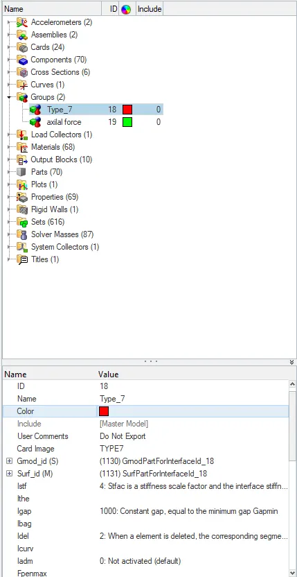
- Before creating this contact make sure to delete the previous contacts.
Rigid Wall:-
- A rigid wall is a nodal constraint applied to a set of slave nodes in order to avoid node penetration to the wall. If contact is
detected, then the slave node acceleration and velocity are modified. - Mainly to constrain the movement of a moving body after impact, we will be using a plane wall. An infinite plane wall is a plane that extends to infinity. It is defined with two points.
- Rigid wall entities provide a method for treating contact between a rigid surface and nodal points of a deformable body. In the Radios, user profiles and rigid walls can be created in the Model and Solver browsers.
- To create an RWALL Go to Model browser > Create > Rigid wall > Plane.
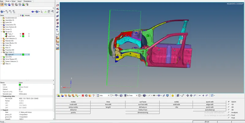
- We need a reference node to create an RWALL so we can select a node at the center of the bumper.
- Based on the reference node we can just adjust the wall in such a way that it is not in contact with the car and there is a small gap
between the wall and the vehicle. - Make sure the Normal of the Rigidwall is facing the Vehicle as shown in the above image. We will be providing the contact interface as
Sliding with friction with a frictional coefficient of 0.1. - The D-search distance we can use is around the range of 1000 mm. All the Nodes within this distance will be considered as salve nodes
for the contact between the car and the Rigid Wall.
Input velocity:-
- The velocity input for this simulation as per the Standards is 35mph so when we convert it to m/s the input velocity is 15.6464m/s.
- To create a velocity Go to solver browser > Create > boundary conditions (BC) > Inivel
- Define the Node group on which specified initial velocities are applied (grnd_ID1). For our simulation, we will be selecting the whole
vehicle setup 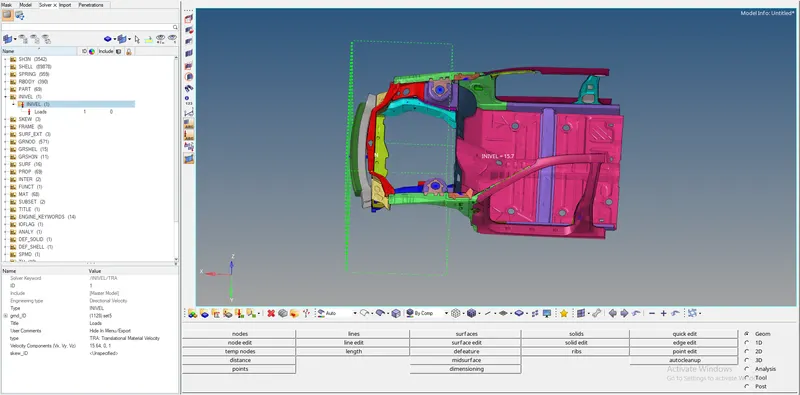
- The velocity type is selected as Translation velocity and it is provided in the x-direction as shown in the above image.
CREATING SECTIONS:-
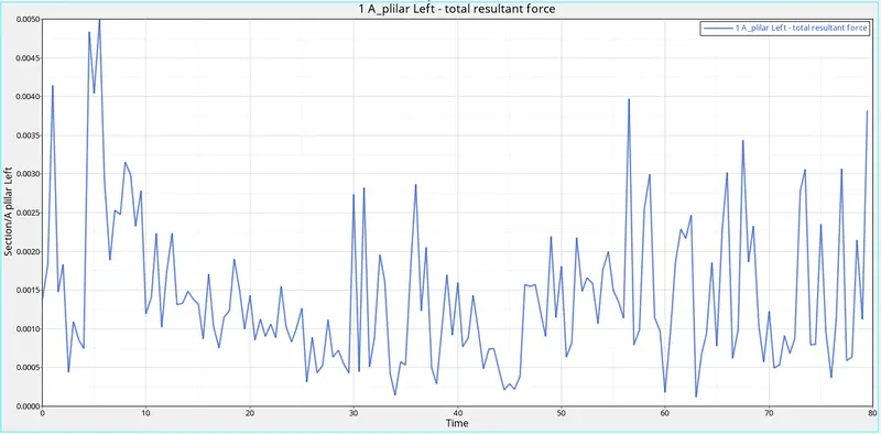
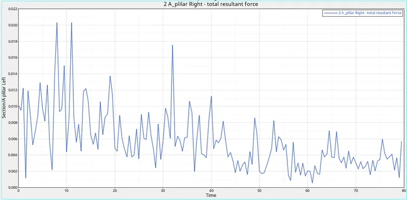
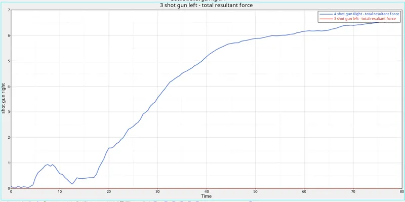
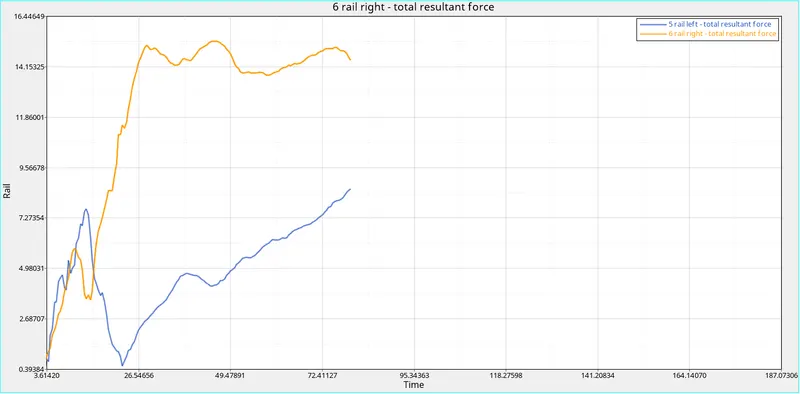
- We will be Creating Sections at A-Pillar, Shot Gun, rails, and the Bumper in order to Study the sectional forces. We have to know-how
the forces are transmitted from the Bumper to the Dashboard and the rate of deformation. - It is done in order to ensure the safety of the passenger. Certain components have to deform more than the other so that the forces are distributed correctly leaving very little force left to transmit inside the cabin.
- We will be using these moving frames to create a section as shown below.
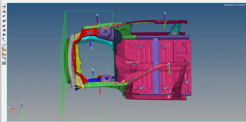
- Define the Nodes with reference to the Axis of the Frame.
- Enter the values of Delta T as 0.6 and Alpha value is 0.1
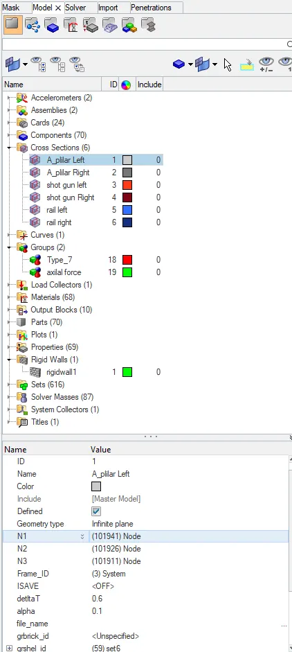
- Define the cutting plane by a group of elements and its orientation by a group of nodes (grshell_ID)
- Hence, the sections will be created.
- We will be creating a TH file separately for both of these sections so that we can view the transfer of force through them.
CREATE ACCELERATION NODES:-
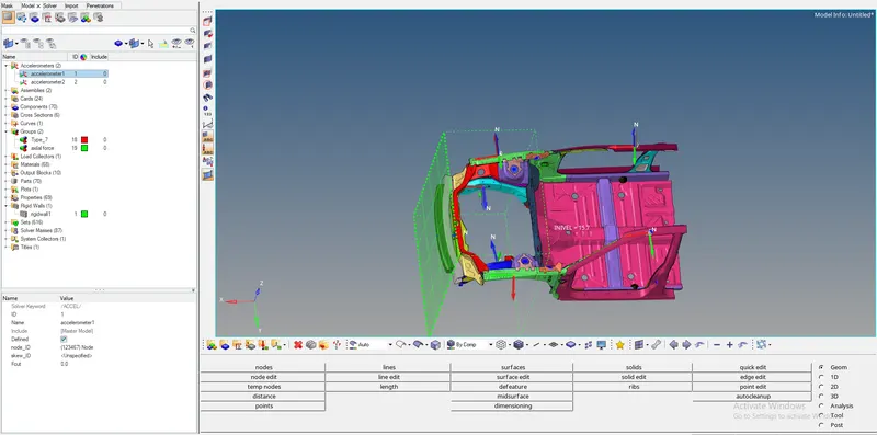
- Creating Accelerometer at both sides of the B pillar.
- An accelerometer is a basic technology that converts mechanical motion into an electrical signal.
- It is an electromechanical device that measures acceleration forces, whether caused by gravity or motion.
- To create accelerometer Go to Model browser > Create >Accelerometer >Select Node_ID >Select node > Proceed.
Intrusions:-
- Near the dash, wall to study the effects of force in the dash wall 66695,66244.
Processor:-
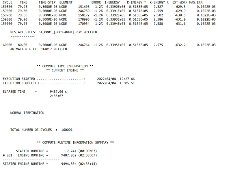
- The simulation ran for 80001 cycles. Energy error is -1.2 % which is acceptable. Mass error is 1.5 % which is also less than 5 % and is
under control as per the simulation.
RUN THE ANALYSIS:
- Analysis > Radioss > Input File: (File Location) >Hit Radios
- The input file is the same Started file (contains model information) that we had just imported.
- The animation video along with the frames will be saved in the same folder where the starter file exists.
- We have to import the animation file in HyperView first: HyperView > FIRST_RUN. h3d > Apply
- The tools to review the simulation are available on HyperView.
- HyperView is a post-processing and visualization environment for FEA that gives the output of the analysis in a simulations
the format that is user-friendly to understand. - From the simulation, we can review how the impact force acts and causes deformations and points of rupture in the model.
VonMises:
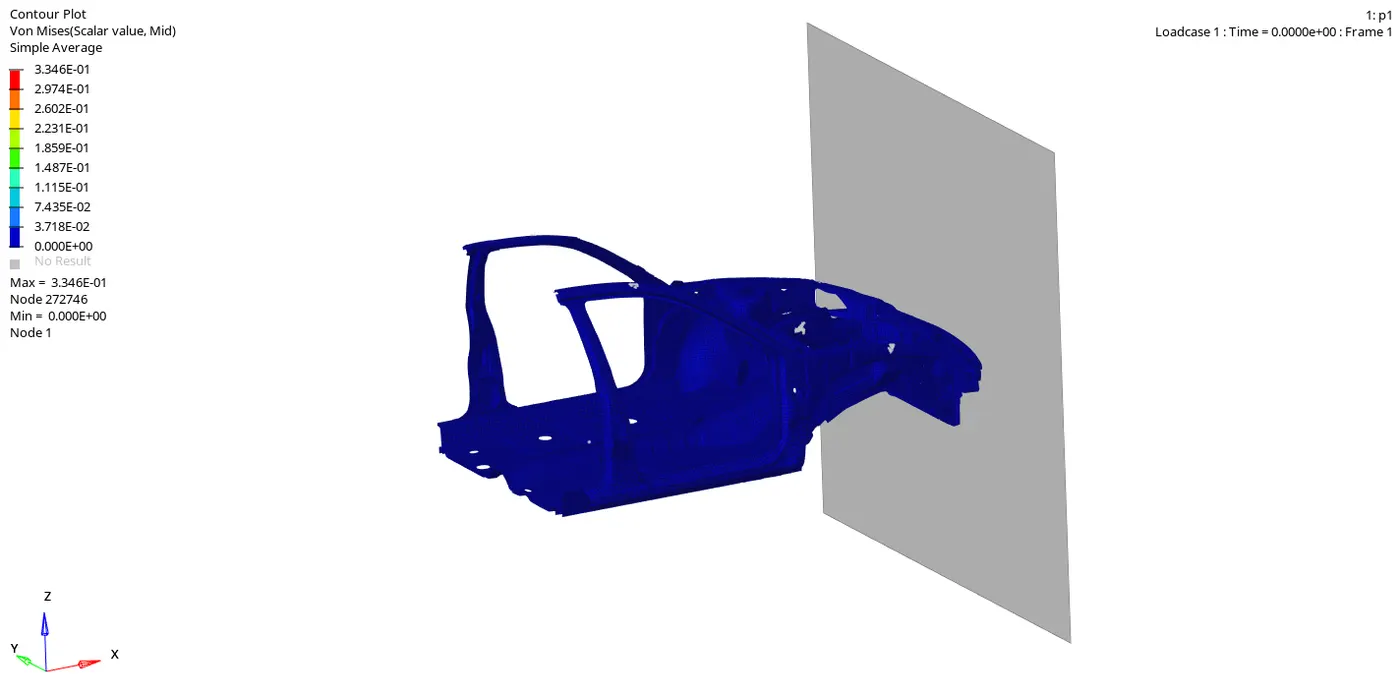
- From the simulation, we can see that, Initially, the bumper starts crushing then the bumper forces are transferred to the left and right
rail from the rail forces is transferred to A-Pillar LH and RH. In each stage, the forces are going to reduce because energy is absorbed
in each stage. Because of no engine blocks, suspension system, etc, the car BIW is going to go down at the end of the simulation.
PLOT THE GRAPH AND COMPARE THE RESULTS:-
- The tools to plot the graph are available on Hypergraph. Hypergraph 2D > Data File > FIRST_RUNT01 > Apply
- A hypergraph is a data analysis and plotting tool that represents the FEA from the simulation in graphs with respect to the selected
unit system.
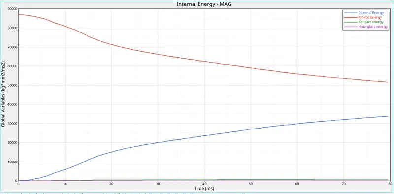
INTERNAL ENERGY AND KINETIC ENERGY:-
A pillar cross-section:-
A-pillar left
A-pillar right
Shotgun cross-sectional forces
Shotgun right & left
Rail:-
Accelerometer:-
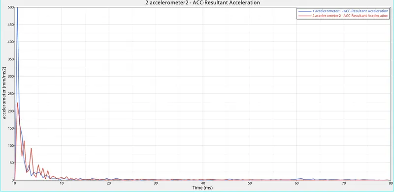
- As we all know that an Acceleration is the rate of change in velocity. To measure the acceleration, we have placed the accelerometer
near the Rocker of B-Pillar on both sides.
Learning Outcome:-
- Learned how to set up a frontal crash test.
- Learned how the Rigid wall interface works and can lead to incompatible Kinematic conditions.
- Learned how Sectional forces are generated.
- Learned how the distribution of forces among the components during a frontal crash.
- Learned how some components are designed to deform in such a way to ensure the safety of the passengers inside the cabin.
- Learned how to check for Energy, mass, and momentum balance.
- Learned how to Debug errors in order to get the right results.
Conclusion:-
- The given model was simulated for the frontal crash using Radios and the results obtained were validated.
- The graphical results were plotted for all the test cases. From the simulation, it can be observed that there was minimum deformation in the cabin, and also minimum intrusion was found in the driver’s seat area.