Assignment 6-Frontal Crash Simulation Challenge
Aim -Crash Simulation of Frontal side of the Dodge Neon Car as per the New Car Assessment Program (NCAP).
Objective
• Check unit system and either follow [Mg mm s] or [Kg mm ms].
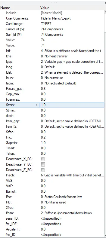
• Create appropriate interface, friction 0.2 and recommended parameters,
• Make sure of no penetrations and intersection.
. Correct rigid bodies if any issues.
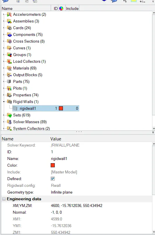
• Create rigid wall with friction 0.1.
• Compare the model weight with the full scale 300k nodes model and use added masses to reach target weight 700kg while getting
CG about the required range.
. Initial velocity 35 mph.
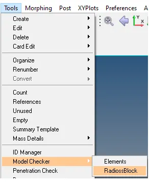
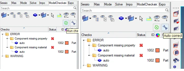
• Use model checker to ensure good quality.
• Time-step:0.5 to 0.1 microseconds.
• Run 80 ms.
Output Request
• Sectional force in the rails at location of indicated node 174247.
Axial force received on the rails from bumper.
Shotgun cross sectional forces.
A pillar cross section.
Acceleration curve received on the accelerometer at base of B pillar (on B pillar rocker).
• Intrusions on the dash wall 66695,66244.
Import Model in HyperMesh
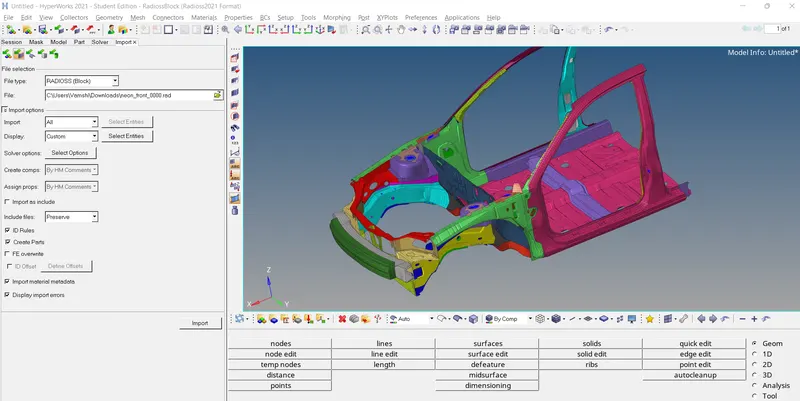
Check for Unit System
The information provided for crash simulation of Neon Car consists of two files are given as follow
neon_front_0000.rad - The file contains information about mesh nodes or element information, components of car, material laws, contact details, boundary conditions, etc. The file made up of ASCII type that contains the essential model information. This file is also called starter file which always end with 0000.rad.
• neon_front_0001.rad file contains information about runtime, time step, animation frequency, no. of animation file, number and size of time history file etc. The file made up of ASCII type that describes running instruction for the solver. This file is also called engine file which always end with 0001.rad.
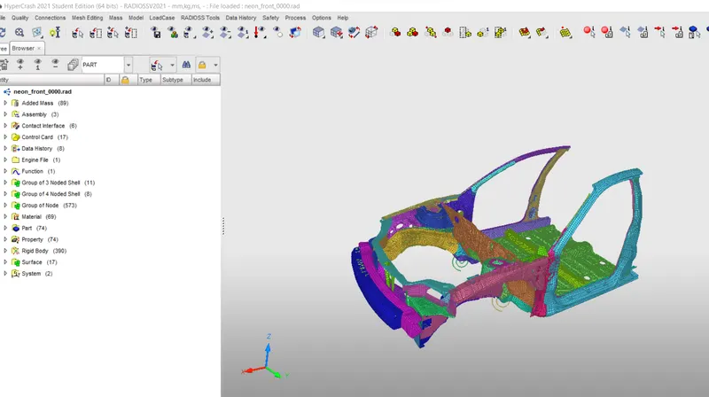
Important operation will be performed in HyperCrash, it will be opened by following (Application >> HyperCrash).
• The starting frame of HyperCrash will be displayed with units (kN mm ms kg) taken in reference as per the units (kg mm ms) in the starter file neon_front_0000.rad and finally select the Run option to open the HyperCrash.
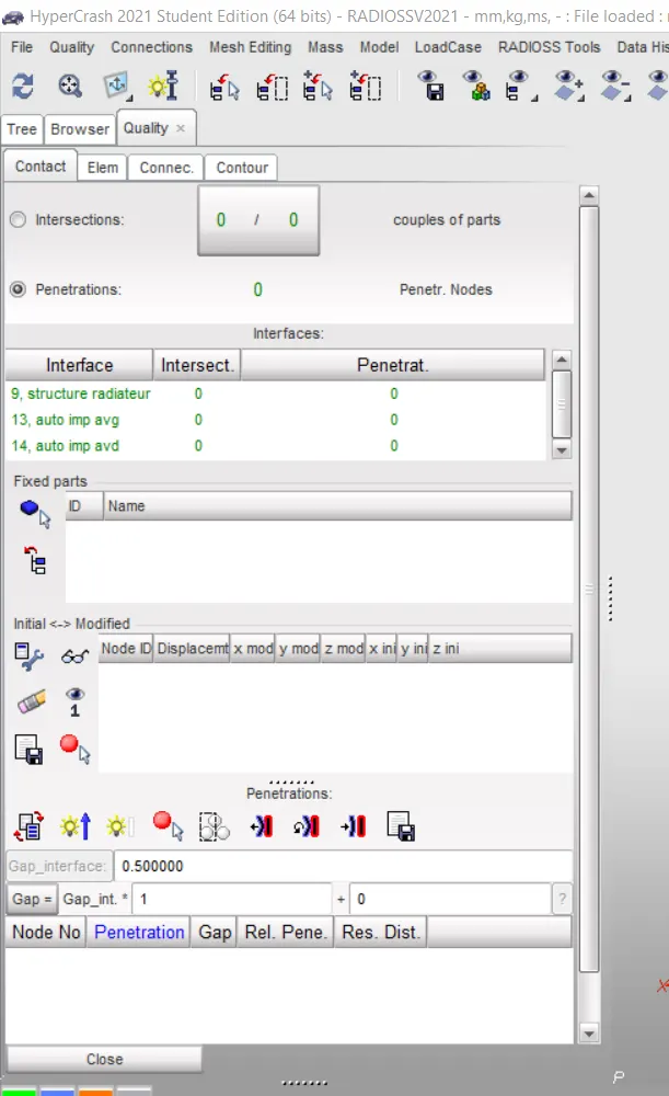
Penetration and Intersection
• Penetration and Intersection operation will be performed by following (Quality >> Check All Solver Contact Interfaces). Contour window will open in which (include picked parts) option selected by following inside the fixed parts windows and finally click on the penetration option.
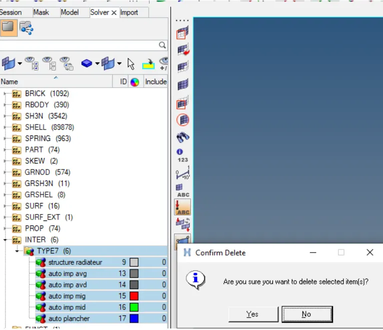
By create the type 7 card for the given component and select the unnecessary items and delete it.
Below shown the creating the TYPE7 contact with the selected the crash test standerd parameters can be selected for the given the model.
then create the rigid wall and assign the data
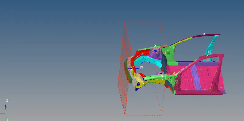
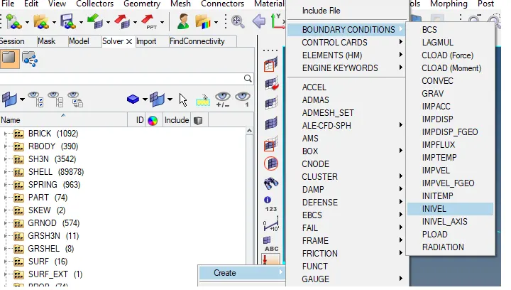
create the boundary condition of selecting the invel in to solver
Acclerometer - The accelerometer will assign to know the how much of acceleration will happen in the particular node we can analyse the condition.
Create the acclerometer for the given component in such a way that the by using the display numers to use and create the specific node of the model with exact opposite node will be select the introduce the node.
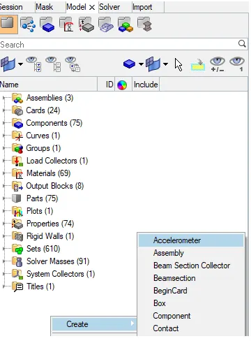
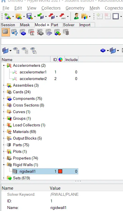
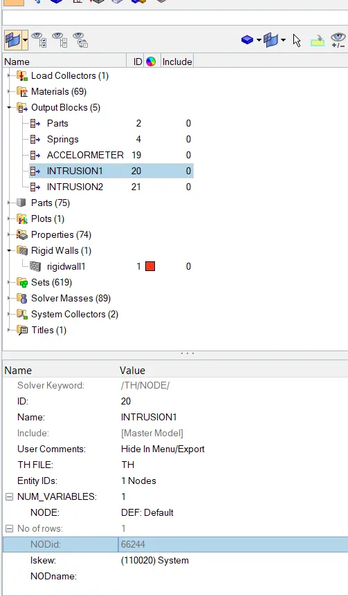
Intrusions-The intrusions will be create because to study in the deformation in the model can be seen through graphical
representation. To create the intrusion spring with help of the display number of 66695.66244 nodes so, crate node in both the node
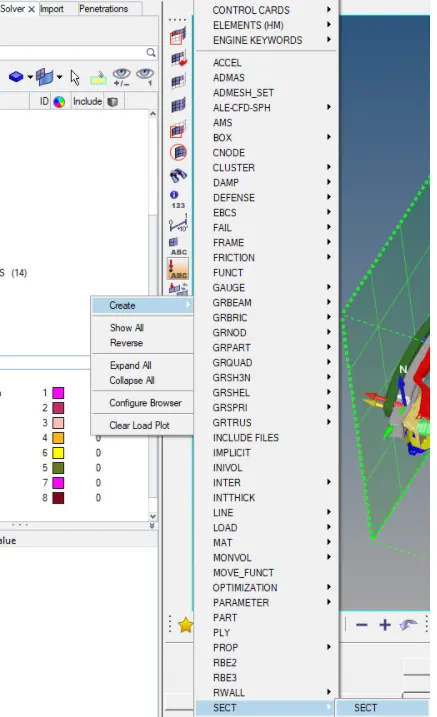
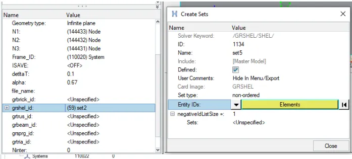
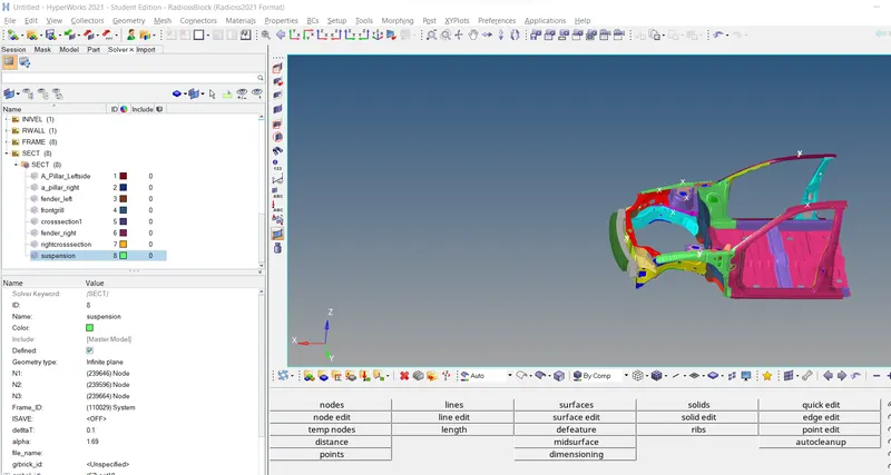
section- In this case we can introduce the sections to know the how much force can be passes through the component we can decide.
The section forces can be introduce in 8 components is of the bumper R/L, rail R/L,short gun R/L and the A-piller.
By selecting the solver browser and create for the SECT and SECT
MODULAR CHECKER
 .
.
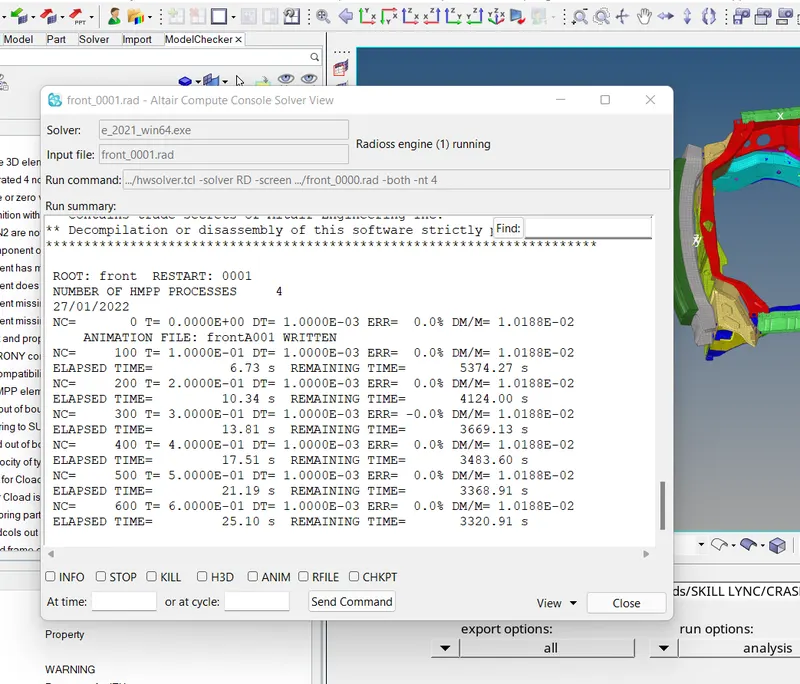
and run by saving in radioos file with connector -nt 4 , we get
then select the h3d and apply
after apply select the contour for the component and the displacement of the car body
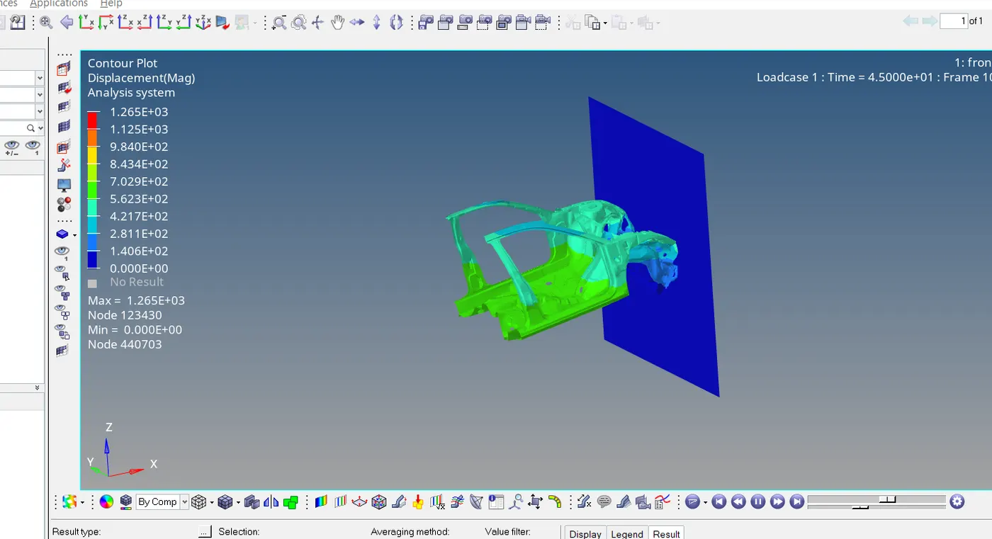
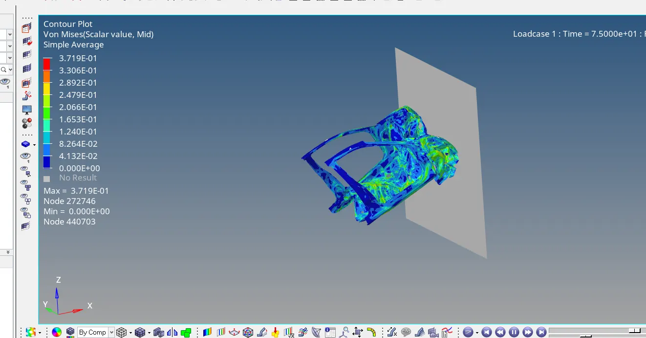
then import T01 file
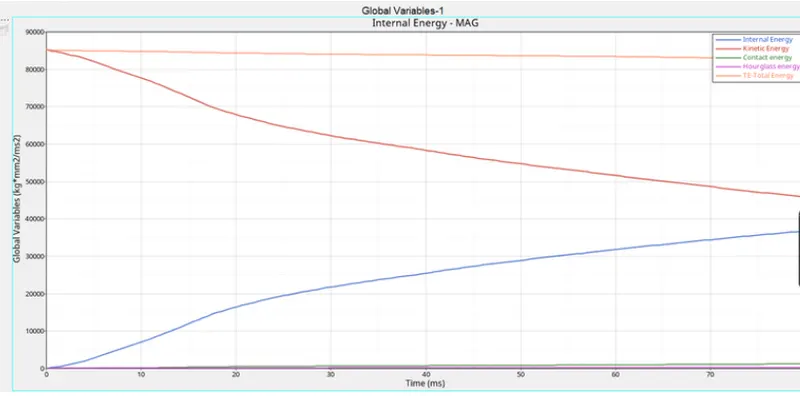
The total energy has to be of resultant of all energies are to become the total energy and its shows the some energy error but it has been acceptable.
• The kinetic energy has been decreasing from the higher energy to lower energy as shown in below figure. It means when the body will hit with the side the kinetic energy of the car has been decreases 0.1596e5 as per the record. • The internal energy has been depends upoun the deformation for the car body. Ingraph there is internal energy has been starts from
the origine, means no deformation at starting, After some time when the car body hit with the pole the body will get deformation. • The hourglass energy has been not effects the because of the standerd parameters of fully intigrated nodes has been assigned in the
parameters. It has been calculated 5% of the internal energy has been trated as the hourglass energy. • The contact energy has been generated due to contact between the car body within the self contact.
In the accelerometer by crating nodes in the right and left side the accelerometer has been have in results will be of 2 different cases shown in below. The basically acceleration is created with the certain amount of the velocity with respect to time.
The right side of the accelerometer output will shows the 336.686 at starting and suddenly gets decreases due to the car model hit with the vigid wall. The acceleration will be drop.
The left side of the accelerometer is found as the 214 892 at staring and it will suddenly draps because of the rigid wall has the reson to deceases the acceleration of rar med
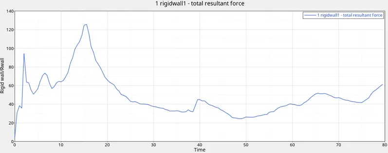
Results
The case setup for the frantal crash test has to achive:
To know the mass balancing for the given component.
The assigning the proper parameters for the TH, INVEL, BCS, skew, accelerometer and intrusions can be determined.
Conclusion
To understand the how to make the frantal crash simulation with assigning the suitable standerd parameters for the frantal crash to the given BIW component.
By analyse the the graph and understand the graph variation happened after simulation.
Compering the results with the graph and also the simulation maid the changes
The real case this frantal crash has been takes place with the total assembly component with the assigning the initial veleocity to move. It has been observed that there is min. deformation cabin and also min, intrusion at the given nodes in passenger compartment.